1999 DODGE NEON wheel bolts
[x] Cancel search: wheel boltsPage 14 of 1200
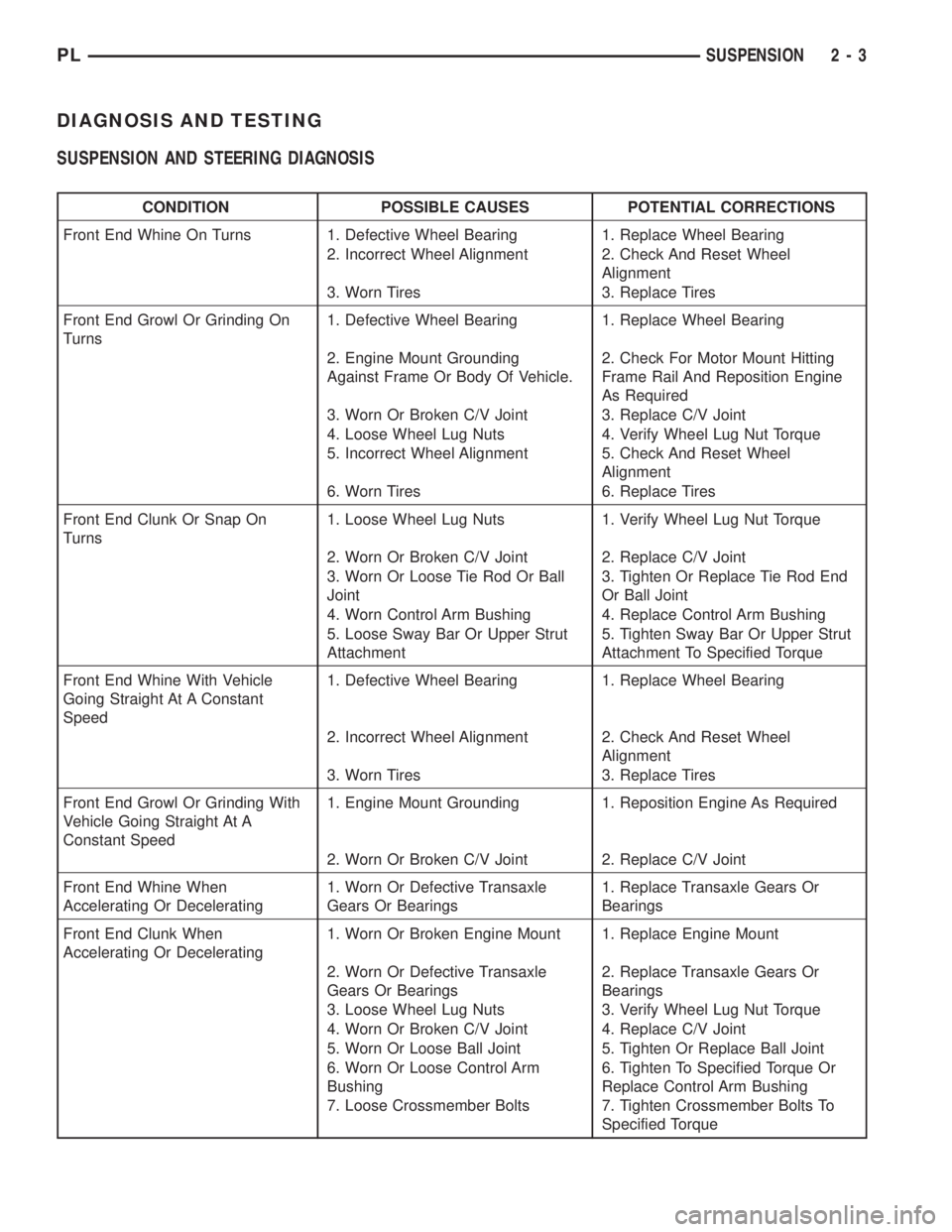
DIAGNOSIS AND TESTING
SUSPENSION AND STEERING DIAGNOSIS
CONDITION POSSIBLE CAUSES POTENTIAL CORRECTIONS
Front End Whine On Turns 1. Defective Wheel Bearing 1. Replace Wheel Bearing
2. Incorrect Wheel Alignment 2. Check And Reset Wheel
Alignment
3. Worn Tires 3. Replace Tires
Front End Growl Or Grinding On
Turns1. Defective Wheel Bearing 1. Replace Wheel Bearing
2. Engine Mount Grounding
Against Frame Or Body Of Vehicle.2. Check For Motor Mount Hitting
Frame Rail And Reposition Engine
As Required
3. Worn Or Broken C/V Joint 3. Replace C/V Joint
4. Loose Wheel Lug Nuts 4. Verify Wheel Lug Nut Torque
5. Incorrect Wheel Alignment 5. Check And Reset Wheel
Alignment
6. Worn Tires 6. Replace Tires
Front End Clunk Or Snap On
Turns1. Loose Wheel Lug Nuts 1. Verify Wheel Lug Nut Torque
2. Worn Or Broken C/V Joint 2. Replace C/V Joint
3. Worn Or Loose Tie Rod Or Ball
Joint3. Tighten Or Replace Tie Rod End
Or Ball Joint
4. Worn Control Arm Bushing 4. Replace Control Arm Bushing
5. Loose Sway Bar Or Upper Strut
Attachment5. Tighten Sway Bar Or Upper Strut
Attachment To Specified Torque
Front End Whine With Vehicle
Going Straight At A Constant
Speed1. Defective Wheel Bearing 1. Replace Wheel Bearing
2. Incorrect Wheel Alignment 2. Check And Reset Wheel
Alignment
3. Worn Tires 3. Replace Tires
Front End Growl Or Grinding With
Vehicle Going Straight At A
Constant Speed1. Engine Mount Grounding 1. Reposition Engine As Required
2. Worn Or Broken C/V Joint 2. Replace C/V Joint
Front End Whine When
Accelerating Or Decelerating1. Worn Or Defective Transaxle
Gears Or Bearings1. Replace Transaxle Gears Or
Bearings
Front End Clunk When
Accelerating Or Decelerating1. Worn Or Broken Engine Mount 1. Replace Engine Mount
2. Worn Or Defective Transaxle
Gears Or Bearings2. Replace Transaxle Gears Or
Bearings
3. Loose Wheel Lug Nuts 3. Verify Wheel Lug Nut Torque
4. Worn Or Broken C/V Joint 4. Replace C/V Joint
5. Worn Or Loose Ball Joint 5. Tighten Or Replace Ball Joint
6. Worn Or Loose Control Arm
Bushing6. Tighten To Specified Torque Or
Replace Control Arm Bushing
7. Loose Crossmember Bolts 7. Tighten Crossmember Bolts To
Specified Torque
PLSUSPENSION 2 - 3
Page 15 of 1200
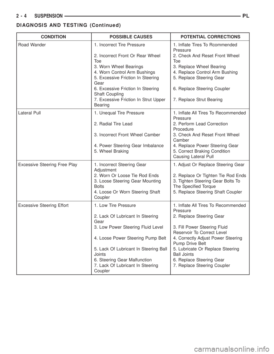
CONDITION POSSIBLE CAUSES POTENTIAL CORRECTIONS
Road Wander 1. Incorrect Tire Pressure 1. Inflate Tires To Rcommended
Pressure
2. Incorrect Front Or Rear Wheel
To e2. Check And Reset Front Wheel
To e
3. Worn Wheel Bearings 3. Replace Wheel Bearing
4. Worn Control Arm Bushings 4. Replace Control Arm Bushing
5. Excessive Friction In Steering
Gear5. Replace Steering Gear
6. Excessive Friction In Steering
Shaft Coupling6. Replace Steering Coupler
7. Excessive Friction In Strut Upper
Bearing7. Replace Strut Bearing
Lateral Pull 1. Unequal Tire Pressure 1. Inflate All Tires To Recommended
Pressure
2. Radial Tire Lead 2. Perform Lead Correction
Procedure
3. Incorrect Front Wheel Camber 3. Check And Reset Front Wheel
Camber
4. Power Steering Gear Imbalance 4. Replace Power Steering Gear
5. Wheel Braking 5. Correct Braking Condition
Causing Lateral Pull
Excessive Steering Free Play 1. Incorrect Steering Gear
Adjustment1. Adjust Or Replace Steering Gear
2. Worn Or Loose Tie Rod Ends 2. Replace Or Tighten Tie Rod Ends
3. Loose Steering Gear Mounting
Bolts3. Tighten Steering Gear Bolts To
The Specified Torque
4. Loose Or Worn Steering Shaft
Coupler5. Replace Steering Shaft Coupler
Excessive Steering Effort 1. Low Tire Pressure 1. Inflate All Tires To Recommended
Pressure
2. Lack Of Lubricant In Steering
Gear2. Replace Steering Gear
3. Low Power Steering Fluid Level 3. Fill Power Steering Fluid
Reservoir To Correct Level
4. Loose Power Steering Pump Belt 4. Correctly Adjust Power Steering
Pump Drive Belt
5. Lack Of Lubricant In Steering Ball
Joints5. Lubricate Or Replace Steering
Ball Joints
6. Steering Gear Malfunction 6. Replace Steering Gear
7. Lack Of Lubricant In Steering
Coupler7. Replace Steering Coupler
2 - 4 SUSPENSIONPL
DIAGNOSIS AND TESTING (Continued)
Page 18 of 1200
COMPETITION PACKAGE ALIGNMENT PROCEDURE
If a vehicle is equipped with the optional competi-
tion package, (S/C ACR) the front wheel camber is
adjustable.
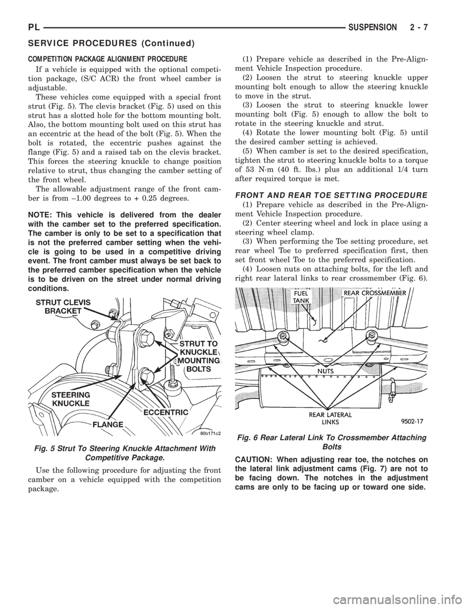
These vehicles come equipped with a special front
strut (Fig. 5). The clevis bracket (Fig. 5) used on this
strut has a slotted hole for the bottom mounting bolt.
Also, the bottom mounting bolt used on this strut has
an eccentric at the head of the bolt (Fig. 5). When the
bolt is rotated, the eccentric pushes against the
flange (Fig. 5) and a raised tab on the clevis bracket.
This forces the steering knuckle to change position
relative to strut, thus changing the camber setting of
the front wheel.
The allowable adjustment range of the front cam-
ber is from ±1.00 degrees to + 0.25 degrees.
NOTE: This vehicle is delivered from the dealer
with the camber set to the preferred specification.
The camber is only to be set to a specification that
is not the preferred camber setting when the vehi-
cle is going to be used in a competitive driving
event. The front camber must always be set back to
the preferred camber specification when the vehicle
is to be driven on the street under normal driving
conditions.
Use the following procedure for adjusting the front
camber on a vehicle equipped with the competition
package.(1) Prepare vehicle as described in the Pre-Align-
ment Vehicle Inspection procedure.
(2) Loosen the strut to steering knuckle upper
mounting bolt enough to allow the steering knuckle
to move in the strut.
(3) Loosen the strut to steering knuckle lower
mounting bolt (Fig. 5) enough to allow the bolt to
rotate in the steering knuckle and strut.
(4) Rotate the lower mounting bolt (Fig. 5) until
the desired camber setting is achieved.
(5) When camber is set to the desired specification,
tighten the strut to steering knuckle bolts to a torque
of 53 N´m (40 ft. lbs.) plus an additional 1/4 turn
after required torque is met.
FRONT AND REAR TOE SETTING PROCEDURE
(1) Prepare vehicle as described in the Pre-Align-
ment Vehicle Inspection procedure.
(2) Center steering wheel and lock in place using a
steering wheel clamp.
(3) When performing the Toe setting procedure, set
rear wheel Toe to preferred specification first, then
set front wheel Toe to the preferred specification.
(4) Loosen nuts on attaching bolts, for the left and
right rear lateral links to rear crossmember (Fig. 6).
CAUTION: When adjusting rear toe, the notches on
the lateral link adjustment cams (Fig. 7) are not to
be facing down. The notches in the adjustment
cams are only to be facing up or toward one side.
Fig. 5 Strut To Steering Knuckle Attachment With
Competitive Package.
Fig. 6 Rear Lateral Link To Crossmember Attaching
Bolts
PLSUSPENSION 2 - 7
SERVICE PROCEDURES (Continued)
Page 19 of 1200
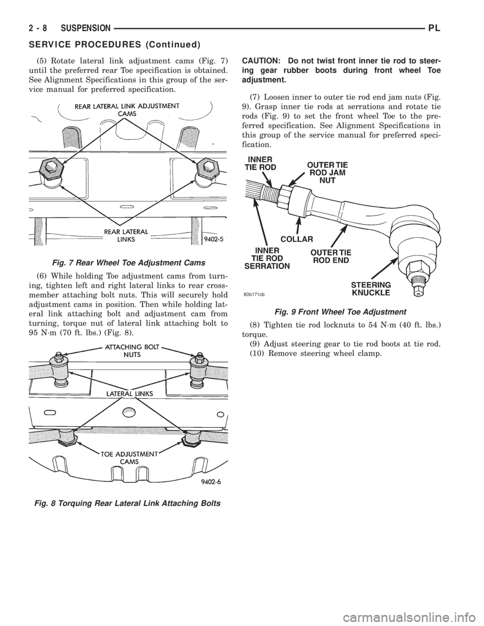
(5) Rotate lateral link adjustment cams (Fig. 7)
until the preferred rear Toe specification is obtained.
See Alignment Specifications in this group of the ser-
vice manual for preferred specification.
(6) While holding Toe adjustment cams from turn-
ing, tighten left and right lateral links to rear cross-
member attaching bolt nuts. This will securely hold
adjustment cams in position. Then while holding lat-
eral link attaching bolt and adjustment cam from
turning, torque nut of lateral link attaching bolt to
95 N´m (70 ft. lbs.) (Fig. 8).CAUTION: Do not twist front inner tie rod to steer-
ing gear rubber boots during front wheel Toe
adjustment.
(7) Loosen inner to outer tie rod end jam nuts (Fig.
9). Grasp inner tie rods at serrations and rotate tie
rods (Fig. 9) to set the front wheel Toe to the pre-
ferred specification. See Alignment Specifications in
this group of the service manual for preferred speci-
fication.
(8) Tighten tie rod locknuts to 54 N´m (40 ft. lbs.)
torque.
(9) Adjust steering gear to tie rod boots at tie rod.
(10) Remove steering wheel clamp.
Fig. 7 Rear Wheel Toe Adjustment Cams
Fig. 8 Torquing Rear Lateral Link Attaching Bolts
Fig. 9 Front Wheel Toe Adjustment
2 - 8 SUSPENSIONPL
SERVICE PROCEDURES (Continued)
Page 27 of 1200

nent removal and installation sections in this group
of the service manual.
BALL JOINT ASSEMBLY
With the weight of the vehicle resting on the road
wheels. Grasp the grease fitting as shown in (Fig. 11)
and with no mechanical assistance or added force
attempt to move the grease fitting.
If the ball joint is worn the grease fitting will move
easily. If movement is noted, replacement of the ball
joint is recommended.
STABILIZER BAR
Inspect for broken or distorted sway bar bushings,
bushing retainers, and worn or damaged sway bar to
strut attaching links. If sway bar to front suspension
cradle bushing replacement is required, bushing can
be removed from sway bar by opening slit and peel-
ing bushing off sway bar.
HUB/BEARING
The hub bearing is designed for the life of the vehi-
cle and requires no type of periodic maintenance. The
following procedure may be used for diagnosing the
condition of the hub bearing.
With the wheel, disc brake caliper, and brake rotor
removed, rotate the wheel hub. Any roughness or
resistance to rotation may indicate dirt intrusion or a
failed hub bearing. If the hub bearing exhibits any of
these conditions during diagnosis, the hub bearing
will require replacement, the bearing is not service-
able.
Damaged bearing seals and the resulting excessive
grease loss may also require bearing replacement.
Moderate grease weapage from the hub bearing is
considered normal and should not require replace-
ment of the hub bearing.
REMOVAL AND INSTALLATION
MCPHERSON STRUT
REMOVE
WARNING: DO NOT REMOVE STRUT ROD NUT
WHILE STRUT ASSEMBLY IS INSTALLED IN VEHI-
CLE, OR BEFORE STRUT ASSEMBLY SPRING IS
COMPRESSED.
(1) Loosen wheel nuts.
(2) Raise vehicle on jack stands or centered on a
frame contact type hoist. See Hoisting in the Lubri-
cation and Maintenance section of this manual, for
the required lifting procedure to be used for this
vehicle.
(3) Remove wheel and tire assembly from location
on front of vehicle requiring strut removal.
(4) If both strut assemblies are removed, mark the
strut assemblies right or left according to which side
of the vehicle they were removed from.
(5) Remove hydraulic brake hose routing bracket
and attaching screw from strut damper bracket. If
vehicle is equipped with Anti-Lock brakes, hydraulic
hose routing bracket is combined with speed sensor
cable routing bracket (Fig. 12).
CAUTION: The steering knuckle to strut assembly
attaching bolts are serrated and must not be turned
during removal. Remove nuts while holding bolts
stationary in the steering knuckles.
(6) Remove the 2 bolts (Fig. 13) attaching the strut
to the steering knuckle.
(7) Remove the 3 nuts attaching the upper mount
of the strut (Fig. 14) to the strut tower of the vehicle
.
INSTALL
(1) Install strut assembly into strut tower, aligning
the 3 studs on the upper strut mount into the holes
in shock tower. Install the 3 upper strut mount
retaining nut and washer assemblies (Fig. 14).
Torque the 3 nuts to 31 N´m (23 ft. lbs.).
CAUTION: The steering knuckle to strut assembly
attaching bolts are serrated and must not be turned
during installation. Install nuts while holding bolts
stationary in the steering knuckles.
(2) Align strut assembly with steering knuckle.
Position arm of steering knuckle into strut assembly,
aligning the strut assembly to steering knuckle
mounting holes. Install the 2 strut assembly to steer-
ing knuckle attaching bolts (Fig. 13). Attaching bolts
should be installed with the nuts facing the front of
the vehicle. Torque both attaching bolts to 53 N´m
Fig. 11 Checking Ball Joint Wear
2 - 16 SUSPENSIONPL
DIAGNOSIS AND TESTING (Continued)
Page 28 of 1200

(40 ft. lbs.) plus an additional 1/4 turn after specified
torque is met.
(3) Install hydraulic brake hose routing bracket
and attaching screw onto strut damper bracket. Ifvehicle is equipped with Anti-Lock brakes, hydraulic
hose routing bracket is combined with speed sensor
cable routing bracket (Fig. 12). Torque bracket
attaching bolts (Fig. 12) to 13 N´m (10 ft. lbs.).
(4) Tighten the wheel mounting stud nuts in
proper sequence until all nuts are torqued to half
specification. Then repeat the tightening sequence to
the full specified torque of 135 N´m (100 ft. lbs.).
STEERING KNUCKLE
REMOVE
(1) Remove cotter pin, nut lock, and spring washer
(Fig. 15).
CAUTION: Wheel bearing damage will result if
after loosening hub nut, vehicle is rolled on the
ground or the weight of the vehicle is allowed to be
supported by the tires.
Fig. 12 Brake Hose And Speed Sensor Cable
Routing Brackets
Fig. 13 Strut To Steering Knuckle Attaching Bolts
Fig. 14 Strut To Shock Tower Mounting
Fig. 15 Cotter Pin, Nut Lock, And Spring Washer
PLSUSPENSION 2 - 17
REMOVAL AND INSTALLATION (Continued)
Page 29 of 1200
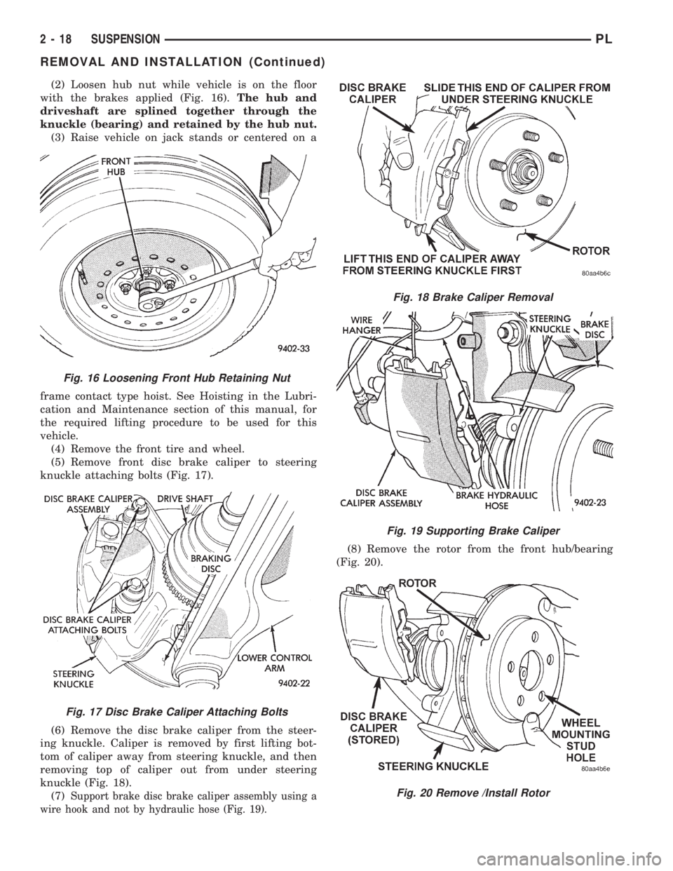
(2) Loosen hub nut while vehicle is on the floor
with the brakes applied (Fig. 16).The hub and
driveshaft are splined together through the
knuckle (bearing) and retained by the hub nut.
(3) Raise vehicle on jack stands or centered on a
frame contact type hoist. See Hoisting in the Lubri-
cation and Maintenance section of this manual, for
the required lifting procedure to be used for this
vehicle.
(4) Remove the front tire and wheel.
(5) Remove front disc brake caliper to steering
knuckle attaching bolts (Fig. 17).
(6) Remove the disc brake caliper from the steer-
ing knuckle. Caliper is removed by first lifting bot-
tom of caliper away from steering knuckle, and then
removing top of caliper out from under steering
knuckle (Fig. 18).
(7)
Support brake disc brake caliper assembly using a
wire hook and not by hydraulic hose (Fig. 19).
(8) Remove the rotor from the front hub/bearing
(Fig. 20).
Fig. 16 Loosening Front Hub Retaining Nut
Fig. 17 Disc Brake Caliper Attaching Bolts
Fig. 18 Brake Caliper Removal
Fig. 19 Supporting Brake Caliper
Fig. 20 Remove /Install Rotor
2 - 18 SUSPENSIONPL
REMOVAL AND INSTALLATION (Continued)
Page 31 of 1200
CAUTION: The steering knuckle to strut assembly
attaching bolts are serrated and must not be turned
during removal. Remove nuts while holding bolts
stationary in the steering knuckles.
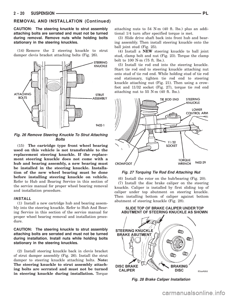
(14) Remove the 2 steering knuckle to strut
damper clevis bracket attaching bolts (Fig. 26).
(15)The cartridge type front wheel bearing
used on this vehicle is not transferable to the
replacement steering knuckle. If the replace-
ment steering knuckle does not come with a
hub and bearing assembly, a new bearing must
be installed in the steering knuckle. Installa-
tion of the new wheel bearing must be done
before installing steering knuckle on vehicle.
Refer to Hub and Bearing Service in this section of
the service manual for proper wheel bearing removal
and installation procedure.
INSTALL
(1) Install a new cartridge hub and bearing assem-
bly into the steering knuckle. Refer to Hub And Bear-
ing Service in this section of the service manual for
proper wheel bearing removal and installation proce-
dure.
CAUTION: The steering knuckle to strut assembly
attaching bolts are serrated and must not be turned
during installation. Install nuts while holding bolts
stationary in the steering knuckles.
(2) Install steering knuckle back in clevis bracket
of strut damper assembly (Fig. 26). Install the strut
damper to steering knuckle attaching bolts.Note:
The steering knuckle to strut assembly attach-
ing bolts are serrated and must not be turned
in steering knuckle during installation.Torqueattaching nuts to 54 N´m (40 ft. lbs.) plus an addi-
tional 1/4 turn after specified torque is met.
(3) Slide drive shaft back into front hub and bear-
ing assembly. Then install steering knuckle onto the
ball joint stud (Fig. 25).
(4) Install aNEWsteering knuckle to ball joint
stud, clamp bolt and nut (Fig. 23). Torque the clamp
bolt to 100 N´m (75 ft. lbs.).
(5) Install tie rod end into the steering knuckle.
Start tie rod end to steering knuckle attaching nut
onto stud of tie rod end. While holding stud of tie rod
end stationary, tighten tie rod end to steering
knuckle attaching nut (Fig. 21). Then using a crow-
foot and 11/32 socket (Fig. 27), torque tie rod end
attaching nut to 55 N´m (40 ft. lbs.).
(6) Install the rotor on the hub/bearing (Fig. 20).
(7) Install the disc brake caliper on the steering
knuckle. Caliper is installed by first sliding top of
caliper under top abutment on steering knuckle.
Then installing bottom of caliper against bottom
abutment of steering knuckle (Fig. 28).
Fig. 28 Brake Caliper Installation
Fig. 26 Remove Steering Knuckle To Strut Attaching
Bolts
Fig. 27 Torquing Tie Rod End Attaching Nut
2 - 20 SUSPENSIONPL
REMOVAL AND INSTALLATION (Continued)