1999 DODGE NEON fuel pump
[x] Cancel search: fuel pumpPage 207 of 1200

WATER PUMP DIAGNOSIS
A quick flow test to tell whether or not the pump is
working is to see if the heater warms properly. A
defective pump will not be able to circulate heated
coolant through the long heater hose.
Another flow test to help determine pump opera-
tion.
WARNING: DO NOT remove radiator cap if the cool-
ing system is hot or under pressure.
(1) Remove radiator cap.
(2) Remove a small amount of coolant from the
system, start the engine and warm up until thermo-
stat opens. With the thermostat open and coolant
level low you will see if the water pump is pumping
coolant through the system.
COOLING SYSTEM FLOW CHECK
To determine whether coolant is flowing through
the cooling system, use the following procedures:
(1) If engine is cold, idle engine until normal oper-
ating temperature is reached. Then feel the upper
radiator hose. If it is hot, coolant is circulating.
WARNING: DO NOT REMOVE THE COOLING SYS-
TEM PRESSURE CAP WITH THE SYSTEM HOT AND
UNDER PRESSURE BECAUSE SERIOUS BURNS
FROM COOLANT CAN OCCUR.
(2) Remove pressure cap when engine is cold,
remove small amount of coolant Idle engine until
thermostat opens, you should observe coolant flow
while looking down the filler neck. Once flow is
detected install the pressure cap.
RADIATOR FAN CONTROL
Fan control is accomplished two ways. The fan
always runs when the air conditioning compressor
clutch is engaged. In addition to this control, the fan
is turned on by the temperature of the coolant which
is sensed by the coolant temperature sensor which
sends the message to the Powertrain Control Module
(PCM). The (PCM) turns on the fan through the
Solid State Fan Relay. The Solid State Fan Relay is
located on the left front inner frame just behind the
radiator. See Wiring Diagrams Manual for circuity
and diagnostics provided.
Switching through the (PCM) provides fan control
for the following conditions.
²The fan will not run during cranking until the
engine starts no matter what the coolant tempera-
ture is.
²Fan will run when the air conditioning clutch is
engaged and low pressure cutout switch is closed.
²Fan will run at vehicle speeds above about 40
mph only if coolant temperature reaches 110ÉC(230ÉF). It will turn off when the temperature drops
to 104ÉC (220ÉF). At speeds below 40 mph the fan
switches on at 102ÉC (215ÉF) and off at 93ÉC (200ÉF).
Refer to Radiator Fan Control Module Group 14,
Fuel Injection for more information.
ELECTRIC FAN MOTOR TEST
Refer to Powertrain Diagnostic Manual for procedure.
TESTING COOLING SYSTEM FOR LEAKS
The system should be full. With the engine not
running, wipe the filler neck sealing seat clean.
Attach a radiator pressure tester to the filler neck,
as shown in (Fig. 9) and apply 104 kPa (15 psi) pres-
sure. If the pressure drops more than 2 psi in 2 min-
utes, inspect the system for external leaks.
Move all hoses at the radiator and heater while
system is pressurize at 15 psi, since some leaks occur
due to engine rock while driving.
If there are no external leaks after the gauge dial
shows a drop in pressure, detach the tester. Start the
engine, and run the engine to normal operating tem-
perature in order to open the thermostat and allow
the coolant to expand. Reattach the tester. If the nee-
dle on the dial fluctuates it indicates a combustion
leak, usually a head gasket leak.
WARNING: WITH THE PRESSURE TESTER IN
PLACE PRESSURE BUILDS UP QUICKLY. ANY
EXCESSIVE PRESSURE BUILD-UP DUE TO CON-
TINUOUS ENGINE OPERATION MUST BE
RELEASED TO A SAFE PRESSURE POINT. NEVER
PERMIT PRESSURE TO EXCEED 138 kPa (20 psi).
If the needle on the dial does not fluctuate, race
the engine a few times. If an abnormal amount of
coolant or steam is emitted from the tail pipe, it may
indicate a faulty head gasket, cracked engine block,
or cracked cylinder head.
Fig. 9 Pressure Testing Cooling SystemÐTypical
7 - 14 COOLINGPL
DIAGNOSIS AND TESTING (Continued)
Page 220 of 1200

NOTE: BLACK OR DARK=0to75%state-of-charge
The battery is INADEQUATELY charged and must
be charged until green dot is visible, (12.4 volts or
greater) before the battery is tested or returned to
use. Refer to Causes of Battery Discharging in this
Group for more information.
NOTE: CLEAR COLOR = Replace Battery
WARNING: DO NOT CHARGE, ASSIST BOOST,
LOAD TEST, OR ADD WATER TO THE BATTERY
WHEN CLEAR COLOR DOT IS VISIBLE. PERSONAL
INJURY MAY OCCUR.
A clear color dot shows electrolyte level in battery
is below the test indicator (Fig. 1). Water cannot be
added to a maintenance free battery. The battery
must be replaced. A low electrolyte level may be
caused by an over charging condition. Refer to Gen-
erator Test Procedures on Vehicle.
CAUSES OF BATTERY DISCHARGING
It is normal to have a small 5 to 25 milliamperes
continuous electrical draw from the battery. This
draw will take place with the ignition in the OFF
position, and the courtesy, dome, storage compart-
ments, and engine compartment lights OFF. The con-
tinuous draw is due to various electronic features or
accessories that require electrical current with the
ignition OFF to function properly. When a vehicle is
not used over an extended period of approximately 20
days the IOD fuse should be pulled. The fuse is
located in the power distribution center. removal of
this fuse will reduce the level of battery discharge.
Refer to the Battery Diagnosis and Testing Table for
proper diagnosis.
ABNORMAL BATTERY DISCHARGING
²Corroded battery posts, cables or terminals.
²Loose or worn generator drive belt.
²Electrical loads that exceed the output of the
charging system due to equipment or accessories
installed after delivery.
²Slow driving speeds in heavy traffic conditions
or prolonged idling with high-amperage electrical
systems in use.
²Defective electrical circuit or component causing
excess Ignition Off Draw (IOD). Refer to Battery
Ignition Off Draw (IOD).
²Defective charging system.
²Defective battery.
BATTERY IGNITION OFF DRAW (IOD)
High current draw on the battery with the ignition
OFF will discharge a battery. After a dead battery is
recharged, the vehicle ignition off draw (IOD) shouldbe checked. To determine if a high current draw con-
dition exists first check the vehicle with a test lamp.
(1) Verify that all electrical accessories are OFF.
²Remove key from ignition switch
²Turn off all lights
²Trunk lid is closed
²Engine compartment hood lamp is disconnected
or lamp removed
²Glove box door is closed
²Sun visor vanity lights are OFF
²All doors are closed
²Allow the ignition key lamp system to time out
in approximately 30 seconds, if equipped.
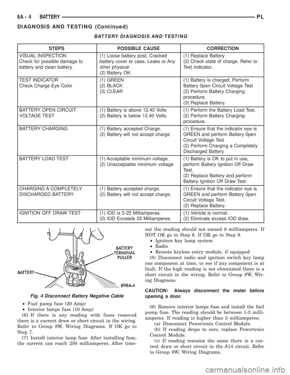
(2) Disconnect battery negative cable (Fig. 4).
(3) Connect a 12 Volt test lamp, with a cold resis-
tance of 5-7 ohms, between the battery negative cable
clamp and the negative post (Fig. 5). If test lamp
goes out system is OK. If test lamp lights and stays
ON, go to Test Lamp Stays ON procedure.
TEST LAMP STAYS ON
There is either a short circuit or a fault in an elec-
tronic module. Two fuses in the Power Distribution
Center (PDC) feed the modules with ignition off
draw.
²Interior lamps fuse (10 Amp) (IOD) PDC.
²Fuel pump fuse (20 Amp) in PDC
(1) Remove interior lamp and fuel pump fuses. By
removing these fuses all ignition off draw from the
vehicle electronics will be disconnected. The test
lamp should go out. If test lamp goes out go to Step
2. If test lamp does not go out there is a current
draw or short circuit. Refer to Group 8W, Wiring Dia-
grams.
(2) Install the fuel pump fuse. If test lamp lights,
there is a current draw or short circuit in the A14
wiring circuit feed.
(a) Disconnect Powertrain Control Module.
(b) If test lamp goes out, replace Powertrain
Control Module.
(c) If test lamp does not go out, there is a cur-
rent draw or short circuit in the A14 circuit feed.
Refer to Group 8W, Wiring Diagrams.
(3) Install the interior lamp fuse. If test lamp
lights, there is a current draw or short circuit in the
M01 circuit. Refer to Group 8W, Wiring Diagrams. If
test lamp stays out, go to Step 4
(4) Use a multi-meter that has at least a range of
200 milliamperes. Install meter between the battery
negative cable and battery negative post (Fig. 6).
Carefully remove the test lamp without disconnecting
the meter. After all modules time-out the total vehi-
cle IOD should be less than 10 milliamperes. If igni-
tion off draw is more than 10 milliamperes go to Step
5.
(5) Remove both fuses from the Power Distribution
Center:
PLBATTERY 8A - 3
DIAGNOSIS AND TESTING (Continued)
Page 221 of 1200

²Fuel pump fuse (20 Amp)
²Interior lamps fuse (10 Amp)
(6) If there is any reading with fuses removed
there is a current draw or short circuit in the wiring.
Refer to Group 8W, Wiring Diagrams. If OK go to
Step 7.
(7) Install interior lamp fuse. After installing fuse,
the current can reach 250 milliamperes. After time-out the reading should not exceed 8 milliamperes. If
NOT OK go to Step 8. If OK go to Step 9.
²Ignition key lamp system
²Radio
²Remote keyless entry module, if equipped
(8) Disconnect radio and ignition switch key lamp
one component at time, to see if any component is at
fault. If the high reading is not eliminated there is a
short circuit in the wiring. Refer to Group 8W, Wir-
ing Diagrams.
CAUTION: Always disconnect the meter before
opening a door.
(9) Remove interior lamps fuse and install the fuel
pump fuse. The reading should be between 1-3 milli-
amperes. If reading is higher than 3 milliamperes:
(a) Disconnect Powertrain Control Module.
(b) If reading drops to zero, replace Powertrain
Control Module.
(c) If reading remains the same there is a cur-
rent draw or short circuit in the A14 circuit. Refer
to Group 8W, Wiring Diagrams.
BATTERY DIAGNOSIS AND TESTING
STEPS POSSIBLE CAUSE CORRECTION
VISUAL INSPECTION
Check for possible damage to
battery and clean battery.(1) Loose battery post, Cracked
battery cover or case, Leaks or Any
other physical
(2) Battery OK.(1) Replace Battery
(2) Check state of charge. Refer to
Test Indicator.
TEST INDICATOR
Check Charge Eye Color(1) GREEN
(2) BLACK
(3) CLEAR(1) Battery is charged. Perform
Battery 0pen Circuit Voltage Test
(2) Perform Battery Charging
procedure.
(3) Replace Battery.
BATTERY OPEN CIRCUIT
VOLTAGE TEST(1) Battery is above 12.40 Volts
(2) Battery is below 12.40 Volts.(1) Perform the Battery Load Test.
(2) Perform Battery Charging
procedure.
BATTERY CHARGING (1) Battery accepted Charge.
(2) Battery will not accept charge(1) Ensure that the indicator eye is
GREEN and perform Battery 0pen
Circuit Voltage Test
(2) Perform Charging a Completely
Discharged Battery.
BATTERY LOAD TEST (1) Acceptable minimum voltage.
(2) Unacceptable minimum voltage(1) Battery is OK to put in use,
perform Battery Ignition Off Draw
Test.
(2) Replace Battery and perform
Battery Ignition Off Draw Test.
CHARGING A COMPLETELY
DISCHARGED BATTERY(1) Battery accepted charge.
(2) Battery will not accept charge.(1) Ensure that the indicator eye is
GREEN and perform Battery 0pen
Circuit Voltage Test.
(2) Replace Battery.
IGNITION OFF DRAW TEST (1) IOD is 5-25 Milliamperes.
(2) IOD Exceeds 25 Milliamperes.(1) Vehicle is normal.
(2) Eliminate excess IOD draw.
Fig. 4 Disconnect Battery Negative Cable
8A - 4 BATTERYPL
DIAGNOSIS AND TESTING (Continued)
Page 252 of 1200

Plastic clips in various locations protect the cables
from damage. When the cables are replaced the clips
must be used to prevent damage to the cables. The
#1 cable must be routed under the PCV hose and
clipped to the #2 cable.
ELECTRONIC IGNITION COILS
WARNING: THE DIRECT IGNITION SYSTEM GEN-
ERATES APPROXIMATELY 40,000 VOLTS. PER-
SONAL INJURY COULD RESULT FROM CONTACT
WITH THIS SYSTEM.
The coil pack consists of 2 coils molded together.
The coil pack is mounted on the valve cover (Fig. 3)
or (Fig. 4). High tension leads route to each cylinder
from the coil. The coil fires two spark plugs every
power stroke. One plug is the cylinder under com-
pression, the other cylinder fires on the exhaust
stroke. Coil number one fires cylinders 1 and 4. Coil
number two fires cylinders 2 and 3. The PCM deter-
mines which of the coils to charge and fire at the cor-
rect time.
The Auto Shutdown (ASD) relay provides battery
voltage to the ignition coil. The PCM provides a
ground contact (circuit) for energizing the coil. When
the PCM breaks the contact, the energy in the coil
primary transfers to the secondary causing the
spark. The PCM will de-energize the ASD relay if it
does not receive the crankshaft position sensor and
camshaft position sensor inputs. Refer to Auto Shut-
down (ASD) RelayÐPCM Output, in this section for
relay operation.
AUTOMATIC SHUTDOWN RELAY
The Automatic Shutdown (ASD) relay supplies bat-
tery voltage to the fuel injectors, electronic ignition
coil and the heating elements in the oxygen sensors.
A buss bar in the Power Distribution Center (PDC)
supplies voltage to the solenoid side and contact sideof the relay. The ASD relay power circuit contains a
20 amp fuse between the buss bar in the PDC and
the relay. The fuse also protects the power circuit for
the fuel pump relay and pump. The fuse is located in
the PDC. Refer to Group 8W, Wiring Diagrams for
circuit information.
The PCM controls the ASD relay by switching the
ground path for the solenoid side of the relay on and
off. The PCM turns the ground path off when the
ignition switch is in the Off position. When the igni-
tion switch is in On or Start, the PCM monitors the
crankshaft and camshaft position sensor signals to
determine engine speed and ignition timing (coil
dwell). If the PCM does not receive crankshaft and
camshaft position sensor signals when the ignition
switch is in the Run position, it will de-energize the
ASD relay.
The ASD relay is located in the PDC (Fig. 5). The
inside top of the PDC cover has label showing relay
and fuse identification.
Fig. 3 Ignition Coil PackÐSOHC
Fig. 4 Ignition Coil PackÐDOHC
Fig. 5 Power Distribution Center (PDC)
PLIGNITION SYSTEM 8D - 3
DESCRIPTION AND OPERATION (Continued)
Page 256 of 1200

train Control Module (PCM) with an input signal
(voltage). The signal represents throttle blade posi-
tion. As the position of the throttle blade changes,
the resistance of the TPS changes.
The PCM supplies approximately 5 volts to the
TPS. The TPS output voltage (input signal to the
powertrain control module) represents throttle blade
position. The TPS output voltage to the PCM varies
from approximately 0.38 volts to 1.2 volts at mini-
mum throttle opening (idle) to a maximum of 3.1
volts to 4.4 volts at wide open throttle.
Along with inputs from other sensors, the PCM
uses the TPS input to determine current engine oper-
ating conditions. The PCM also adjusts fuel injector
pulse width and ignition timing based on these
inputs.
IGNITION SWITCH
In the RUN position, the ignition switch connects
power from the Power Distribution Center (PDC) to a
30 amp fuse in the fuse block, back to a bus bar in
the PDC. The bus bar feeds circuits for the Power-
train Control Module (PCM), duty cycle purge sole-
noid, EGR solenoid, and ABS system. The bus bar in
the PDC feeds the coil side of the radiator fan relay,
A/C compressor clutch relay, and the fuel pump relay.
It also feeds the Airbag Control Module (ACM)
LOCK KEY CYLINDER
The lock cylinder is inserted in the end of the
housing opposite the ignition switch. The ignition key
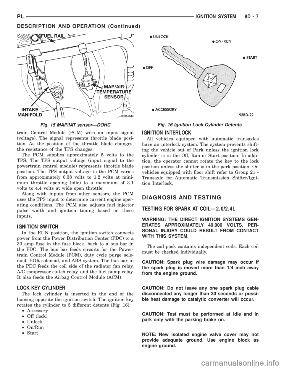
rotates the cylinder to 5 different detents (Fig. 16):
²Accessory
²Off (lock)
²Unlock
²On/Run
²Start
IGNITION INTERLOCK
All vehicles equipped with automatic transaxles
have an interlock system. The system prevents shift-
ing the vehicle out of Park unless the ignition lock
cylinder is in the Off, Run or Start position. In addi-
tion, the operator cannot rotate the key to the lock
position unless the shifter is in the park position. On
vehicles equipped with floor shift refer to Group 21 -
Transaxle for Automatic Transmission Shifter/Igni-
tion Interlock.
DIAGNOSIS AND TESTING
TESTING FOR SPARK AT COILÐ2.0/2.4L
WARNING: THE DIRECT IGNITION SYSTEMS GEN-
ERATES APPROXIMATELY 40,000 VOLTS. PER-
SONAL INJURY COULD RESULT FROM CONTACT
WITH THIS SYSTEM.
The coil pack contains independent coils. Each coil
must be checked individually.
CAUTION: Spark plug wire damage may occur if
the spark plug is moved more than 1/4 inch away
from the engine ground.
CAUTION: Do not leave any one spark plug cable
disconnected any longer than 30 seconds or possi-
ble heat damage to catalytic converter will occur.
CAUTION: Test must be performed at idle and in
park only with the parking brake on.
NOTE: New isolated engine valve cover may not
provide adequate ground. Use engine block as
engine ground.
Fig. 15 MAP/IAT sensorÐDOHCFig. 16 Ignition Lock Cylinder Detents
PLIGNITION SYSTEM 8D - 7
DESCRIPTION AND OPERATION (Continued)
Page 410 of 1200

8W-02 COMPONENT INDEX
Component Page
A/C Compressor Clutch..................8W-42
A/C Compressor Clutch Relay.............8W-42
A/C Cycling Switch.....................8W-42
A/C Heater Blower Motor................8W-42
A/C Heater Control.....................8W-42
A/C Pressure Switches...................8W-42
ABS Warning Lamp Relay................8W-35
Airbag Control Module...................8W-43
Airbags..............................8W-43
Antenna..............................8W-47
Ash Receiver Lamp.....................8W-44
Automatic Shut Down Relay..............8W-30
Back-Up Lamp Switch...................8W-51
Back-Up Lamps........................8W-51
Battery..............................8W-20
Battery Temperature Sensor..............8W-30
Blower Motor Resistor Block..............8W-42
Brake Warning Lamp Switch...........8W-40, 50
Camshaft Position Sensor................8W-30
Center High Mounted Stop Lamp..........8W-51
Cigar Lighter Relay.....................8W-41
Cigar Lighter/Power Outlet...............8W-41
Circuit Breakers.......................8W-11
Clockspring.....................8W-30, 41, 61
Clutch Pedal Position Switch...........8W-10, 21
Combination Flasher....................8W-52
Controller Anti-Lock Brake...............8W-35
Crankshaft Position Sensor...............8W-30
Data Link Connector....................8W-30
Daytime Running Lamp Module...........8W-50
Diode No. 1........................8W-15, 42
Diode No. 2......................8W-10, 11, 44
Diode No. 3......................8W-11,44,70
Dome Lamp...........................8W-44
Door Ajar Switches.....................8W-44
Door Jamb Switches....................8W-44
Door Lock Motors......................8W-61
Door Lock Motors......................8W-61
Door Lock Switches.....................8W-61
Duty Cycle Evap/Purge Solenoid...........8W-30
EGR Transducer Solenoid................8W-30
Engine Coolant Temperature Sensor........8W-30
Engine Oil Pressure Switch...............8W-40
Engine Starter Motor....................8W-21
Engine Starter Motor Relay...............8W-21
Fog Lamp Relays....................8W-50, 51
Fog Lamp Switches..................8W-50, 51
Fog Lamps.........................8W-50, 51
Fuel Injectors..........................8W-30
Fuel Pump Module.....................8W-30
Fuel Pump Relay.......................8W-30
Fuse Block............................8W-11Component Page
Fuses (FB)............................8W-11
Fuses (PDC)...........................8W-10
Fusible Link........................8W-20, 21
Generator.............................8W-20
Glove Box Lamp And Switch..............8W-44
Grounds..............................8W-15
Halo Lamp............................8W-44
Headlamp Dimmer And Optical Horn Switch .8W-50
Headlamp Leveling Motors...............8W-50
Headlamp Leveling Switch...............8W-50
Headlamp Switch.......................8W-50
Headlamps............................8W-50
High Speed Warning Module..............8W-40
Horn Relay...........................8W-41
Horn Switches.........................8W-41
Horns................................8W-41
IAT/Map Sensor........................8W-30
Idle Air Control Motor...................8W-30
Ignition Coil Pack......................8W-30
Ignition Switch........................8W-10
Illumination Lamps.....................8W-40
Immobilizer...........................8W-61
Immobilizer Engine Sensor............8W-30, 61
Indicator Lamps........................8W-40
Instrument Cluster.....................8W-40
Intermittent Wipe/Wash Switch............8W-53
Key-In Switch.........................8W-40
Knock Sensor..........................8W-30
License Lamps.........................8W-51
Map/Reading Lamps....................8W-44
Noise Supressor.....................8W-10, 30
Oxygen Sensors........................8W-30
Park Brake Switch...................8W-40, 50
Park/Neutral Position Switch...........8W-30, 51
Park/Turn Signal Lamps..............8W-50, 52
Power Distribution Center................8W-10
Power Folding Mirror Relay...............8W-62
Power Mirror Fuse Holder................8W-62
Power Mirrors.........................8W-62
Power Steering Pressure Switch...........8W-30
Power Sunroof Motor....................8W-64
Power Window Motors...................8W-60
Power Window Switches.................8W-60
Powertrain Control Module...............8W-30
PRNDL Lamp.........................8W-44
Radiator Fan Motor.....................8W-42
Radio................................8W-47
Rear Window Defogger..................8W-48
Rear Window Defogger Switch.............8W-48
Remote Keyless Entry Module.............8W-61
Remote Keyless Entry Program
Module Connector....................8W-61
PL8W - 02 COMPONENT INDEX 8W - 02 - 1
Page 412 of 1200

8W-10 POWER DISTRIBUTION
Component Page
A/C Compressor Clutch.............8W-10-14, 15
A/C Compressor Clutch Relay........8W-10-14, 15
Automatic Shut Down Relay............8W-10-16
Battery...........................8W-10-5, 6
Capacitor..........................8W-10-16
Circuit Breaker.......................8W-10-8
Clutch Pedal Position Switch.......8W-10-9, 10, 11
Controller Anti-Lock Brake.......8W-10-12, 14, 15
Data Link Connector..................8W-10-16
Diode No. 1......................8W-10-14, 15
Diode No. 2.........................8W-10-13
Dome Lamp........................8W-10-13
Downstream Heated Oxygen Sensor......8W-10-16
Engine Starter Motor..................8W-10-7
Engine Starter Motor Relay......8W-10-7, 9, 10, 11
Fog Lamp Relay.....................8W-10-17
Fuel Injector No. 1...................8W-10-16
Fuel Injector No. 2...................8W-10-16
Fuel Injector No. 3...................8W-10-16
Fuel Injector No. 4...................8W-10-16
Fuel Pump Module...................8W-10-16
Fuel Pump Relay....................8W-10-16
Fuse 1 (FB)..........................8W-10-8
Fuse 2 (FB)..........................8W-10-8
Fuse 2 (PDC).....................8W-10-5, 6, 7
Fuse 3 (FB)..........................8W-10-8
Fuse 3 (PDC).....................8W-10-5, 6, 8
Fuse 4 (FB)..........................8W-10-8
Fuse 5 (FB)..........................8W-10-8
Fuse 5 (PDC)....................8W-10-5, 6, 12
Fuse 6 (FB)..........................8W-10-8
Fuse 7 (FB)..........................8W-10-8
Fuse 8 (FB)..........................8W-10-8
Fuse 8 (PDC)....................8W-10-5, 6, 12
Fuse 9 (FB).......................8W-10-9, 10
Fuse 10 (FB)...................8W-10-9, 10, 11
Fuse 10 (PDC)...................8W-10-5, 6, 12
Fuse 11 (FB)...................8W-10-9, 10, 11
Fuse 11 (PDC)....................8W-10-5, 6, 7
Fuse 12 (FB)........................8W-10-11
Fuse 13 (PDC)...................8W-10-5, 6, 13
Fuse 14 (FB)...................8W-10-9, 10, 11
Fuse 15 (FB)...................8W-10-9, 10, 11
Fuse 16 (FB)...................8W-10-9, 10, 11Component Page
Fuse 16 (PDC).....................8W-10-6, 17
Fuse 18 (PDC)................8W-10-5, 6, 14, 15
Fuse 20 (PDC)................8W-10-5, 6, 14, 15
Fuse 21 (PDC)...................8W-10-5, 6, 16
Fuse 23 (PDC)................8W-10-5, 6, 14, 15
Fuse 25 (PDC)................8W-10-5, 6, 14, 15
Fuse Block...................8W-10-8, 9, 10, 11
G101...............................8W-10-9
G204...............................8W-10-7
Generator..........................8W-10-16
Glove Box Lamp And Switch............8W-10-13
Headlamp Switch.....................8W-10-8
High Speed Warning Module...........8W-10-13
Horn..............................8W-10-14
Horn No. 1.........................8W-10-15
Horn No. 2.........................8W-10-15
Horn Relay......................8W-10-14, 15
Ignition Coil Pack....................8W-10-16
Ignition Switch.............8W-10-7, 8, 9, 10, 11
Immobilizer......................8W-10-10, 11
Instrument Cluster.................8W-10-7, 13
Left Fog Lamp......................8W-10-17
Left Visor/Vanity Lamps...............8W-10-13
Map/Reading Lamps..................8W-10-13
Noise Supressor.....................8W-10-16
Power Distribution
Center.....8W-10-5, 6, 7, 8, 12, 13, 14, 15, 16, 17
Power Mirror Switch..................8W-10-13
Powertrain Control Module...........8W-10-9, 16
Radiator Fan Motor..................8W-10-12
Radio..............................8W-10-13
Rear Fog Lamp Switch................8W-10-17
Rear Window Defogger Switch..........8W-10-12
Right Fog Lamp.....................8W-10-17
Right Visor/Vanity Lamps..............8W-10-13
Solid State Fan Relay.................8W-10-12
Stop Lamp Switch.................8W-10-14, 15
Time Delay Relay....................8W-10-13
Time Out Relay......................8W-10-13
Trunk Lamp........................8W-10-13
Turn Signal/Hazard Switch..........8W-10-14, 15
Underhood Lamp....................8W-10-13
Upstream Heated Oxygen Sensor........8W-10-16
PL8W - 10 POWER DISTRIBUTION 8W - 10 - 1
Page 413 of 1200

NOT
USEDFUEL
PUMP
RELAYAUTO
SHUT
DOWN
RELAYHORN
RELAY
A/C
COMPRESSOR
CLUTCH
RELAYENGINE
STARTER
MOTOR
RELAY
FUSE
25
13 FUSE
16 FUSE
FUSE
1823 FUSE
FUSE
21
20 FUSE
FUSE 10 FUSE 11
FUSE 2 FUSE 3
FUSE 5
FUSE 8
TOP OF
POWER DISTRIBUTION CENTER
PDC FUSE APPLICATION CHART
FUSE NO. AMPS CIRCUIT FUNCTION
240A A2 12PK/BK FUSED B(+)
A3 12RD/WT
A16 14GY 40A
3
530A
A4 14BK/RD
A20 12RD/DG 30A
8
A1 14RD 40A
10
1130A
M1 18PK
1310A
M1 18PK
INTERNAL F61 18WT/OR
20A
16 *
2010A
INTERNAL 1820A
L9 18BK/WT
INTERNAL 20A
21
F32 18PK/DB 15A
23
15A
25INTERNAL RELAYLAMPFOG
RELAYLAMP WARNINGABS
16 **--FUSED B(+)
FUSED B(+)
FUSED B(+)
FUSED B(+)
FUSED B(+)
FUSED B(+)
FUSED B(+)
NOT USED
FUSED B(+)
FUSED B(+)
FUSED B(+)
FUSED B(+)
FUSED B(+)
FUSED B(+)
FUSED B(+)
* BUILT-UP-EXPORT
** EXCEPT BUILT-UP-EXPORT
8W - 10 - 2 8W-10 POWER DISTRIBUTIONPL
J988W-18188