1999 DODGE NEON low beam
[x] Cancel search: low beamPage 237 of 1200
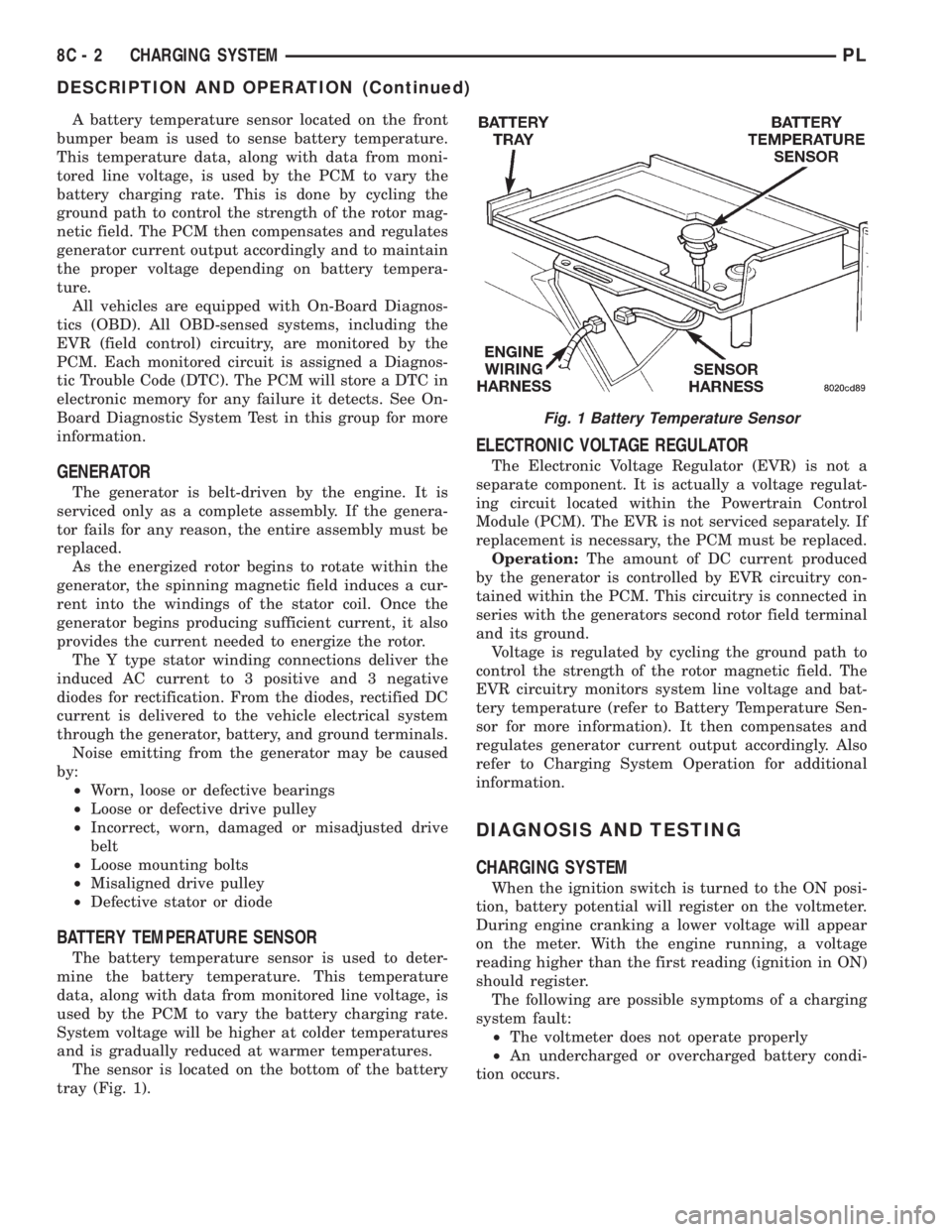
A battery temperature sensor located on the front
bumper beam is used to sense battery temperature.
This temperature data, along with data from moni-
tored line voltage, is used by the PCM to vary the
battery charging rate. This is done by cycling the
ground path to control the strength of the rotor mag-
netic field. The PCM then compensates and regulates
generator current output accordingly and to maintain
the proper voltage depending on battery tempera-
ture.
All vehicles are equipped with On-Board Diagnos-
tics (OBD). All OBD-sensed systems, including the
EVR (field control) circuitry, are monitored by the
PCM. Each monitored circuit is assigned a Diagnos-
tic Trouble Code (DTC). The PCM will store a DTC in
electronic memory for any failure it detects. See On-
Board Diagnostic System Test in this group for more
information.
GENERATOR
The generator is belt-driven by the engine. It is
serviced only as a complete assembly. If the genera-
tor fails for any reason, the entire assembly must be
replaced.
As the energized rotor begins to rotate within the
generator, the spinning magnetic field induces a cur-
rent into the windings of the stator coil. Once the
generator begins producing sufficient current, it also
provides the current needed to energize the rotor.
The Y type stator winding connections deliver the
induced AC current to 3 positive and 3 negative
diodes for rectification. From the diodes, rectified DC
current is delivered to the vehicle electrical system
through the generator, battery, and ground terminals.
Noise emitting from the generator may be caused
by:
²Worn, loose or defective bearings
²Loose or defective drive pulley
²Incorrect, worn, damaged or misadjusted drive
belt
²Loose mounting bolts
²Misaligned drive pulley
²Defective stator or diode
BATTERY TEMPERATURE SENSOR
The battery temperature sensor is used to deter-
mine the battery temperature. This temperature
data, along with data from monitored line voltage, is
used by the PCM to vary the battery charging rate.
System voltage will be higher at colder temperatures
and is gradually reduced at warmer temperatures.
The sensor is located on the bottom of the battery
tray (Fig. 1).
ELECTRONIC VOLTAGE REGULATOR
The Electronic Voltage Regulator (EVR) is not a
separate component. It is actually a voltage regulat-
ing circuit located within the Powertrain Control
Module (PCM). The EVR is not serviced separately. If
replacement is necessary, the PCM must be replaced.
Operation:The amount of DC current produced
by the generator is controlled by EVR circuitry con-
tained within the PCM. This circuitry is connected in
series with the generators second rotor field terminal
and its ground.
Voltage is regulated by cycling the ground path to
control the strength of the rotor magnetic field. The
EVR circuitry monitors system line voltage and bat-
tery temperature (refer to Battery Temperature Sen-
sor for more information). It then compensates and
regulates generator current output accordingly. Also
refer to Charging System Operation for additional
information.
DIAGNOSIS AND TESTING
CHARGING SYSTEM
When the ignition switch is turned to the ON posi-
tion, battery potential will register on the voltmeter.
During engine cranking a lower voltage will appear
on the meter. With the engine running, a voltage
reading higher than the first reading (ignition in ON)
should register.
The following are possible symptoms of a charging
system fault:
²The voltmeter does not operate properly
²An undercharged or overcharged battery condi-
tion occurs.
Fig. 1 Battery Temperature Sensor
8C - 2 CHARGING SYSTEMPL
DESCRIPTION AND OPERATION (Continued)
Page 242 of 1200
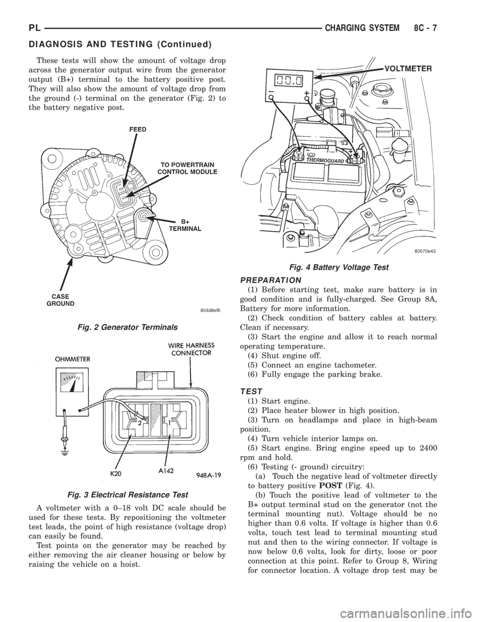
These tests will show the amount of voltage drop
across the generator output wire from the generator
output (B+) terminal to the battery positive post.
They will also show the amount of voltage drop from
the ground (-) terminal on the generator (Fig. 2) to
the battery negative post.
A voltmeter with a 0±18 volt DC scale should be
used for these tests. By repositioning the voltmeter
test leads, the point of high resistance (voltage drop)
can easily be found.
Test points on the generator may be reached by
either removing the air cleaner housing or below by
raising the vehicle on a hoist.
PREPARATION
(1) Before starting test, make sure battery is in
good condition and is fully-charged. See Group 8A,
Battery for more information.
(2) Check condition of battery cables at battery.
Clean if necessary.
(3) Start the engine and allow it to reach normal
operating temperature.
(4) Shut engine off.
(5) Connect an engine tachometer.
(6) Fully engage the parking brake.
TEST
(1) Start engine.
(2) Place heater blower in high position.
(3) Turn on headlamps and place in high-beam
position.
(4) Turn vehicle interior lamps on.
(5) Start engine. Bring engine speed up to 2400
rpm and hold.
(6) Testing (- ground) circuitry:
(a) Touch the negative lead of voltmeter directly
to battery positivePOST(Fig. 4).
(b) Touch the positive lead of voltmeter to the
B+ output terminal stud on the generator (not the
terminal mounting nut). Voltage should be no
higher than 0.6 volts. If voltage is higher than 0.6
volts, touch test lead to terminal mounting stud
nut and then to the wiring connector. If voltage is
now below 0.6 volts, look for dirty, loose or poor
connection at this point. Refer to Group 8, Wiring
for connector location. A voltage drop test may be
Fig. 2 Generator Terminals
Fig. 3 Electrical Resistance Test
Fig. 4 Battery Voltage Test
PLCHARGING SYSTEM 8C - 7
DIAGNOSIS AND TESTING (Continued)
Page 271 of 1200
When the ignition switch is in the OFF position, or
when the radio frequency is being displayed, time
keeping is accurately maintained.
The procedure for setting the clock varies slightly
with each radio. The correct procedure is described in
the individual radio operating instructions. Refer to
the Owner's Manual supplied with the vehicle.
INSTRUMENT CLUSTER
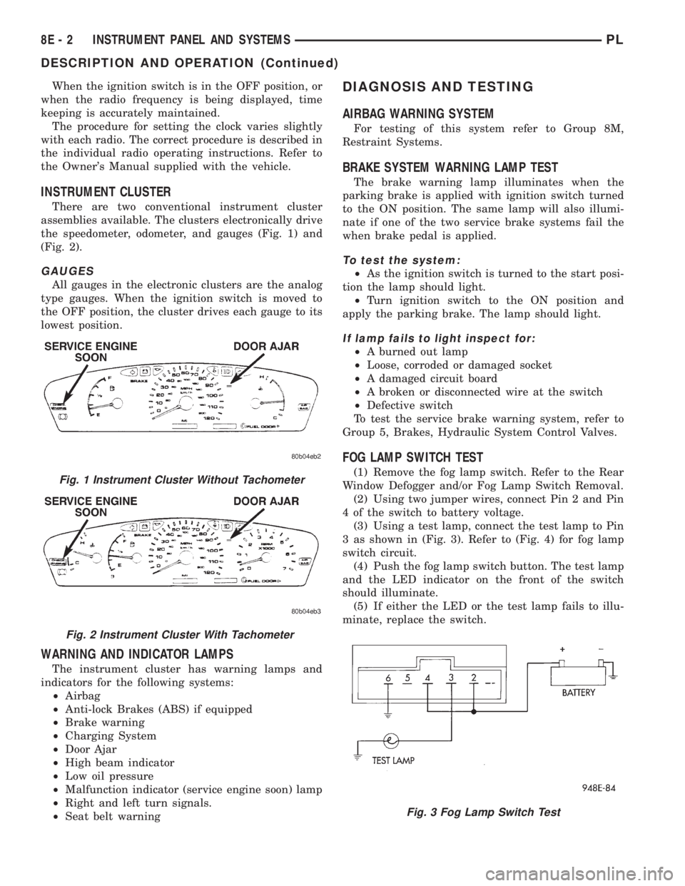
There are two conventional instrument cluster
assemblies available. The clusters electronically drive
the speedometer, odometer, and gauges (Fig. 1) and
(Fig. 2).
GAUGES
All gauges in the electronic clusters are the analog
type gauges. When the ignition switch is moved to
the OFF position, the cluster drives each gauge to its
lowest position.
WARNING AND INDICATOR LAMPS
The instrument cluster has warning lamps and
indicators for the following systems:
²Airbag
²Anti-lock Brakes (ABS) if equipped
²Brake warning
²Charging System
²Door Ajar
²High beam indicator
²Low oil pressure
²Malfunction indicator (service engine soon) lamp
²Right and left turn signals.
²Seat belt warning
DIAGNOSIS AND TESTING
AIRBAG WARNING SYSTEM
For testing of this system refer to Group 8M,
Restraint Systems.
BRAKE SYSTEM WARNING LAMP TEST
The brake warning lamp illuminates when the
parking brake is applied with ignition switch turned
to the ON position. The same lamp will also illumi-
nate if one of the two service brake systems fail the
when brake pedal is applied.
To test the system:
²As the ignition switch is turned to the start posi-
tion the lamp should light.
²Turn ignition switch to the ON position and
apply the parking brake. The lamp should light.
If lamp fails to light inspect for:
²A burned out lamp
²Loose, corroded or damaged socket
²A damaged circuit board
²A broken or disconnected wire at the switch
²Defective switch
To test the service brake warning system, refer to
Group 5, Brakes, Hydraulic System Control Valves.
FOG LAMP SWITCH TEST
(1) Remove the fog lamp switch. Refer to the Rear
Window Defogger and/or Fog Lamp Switch Removal.
(2) Using two jumper wires, connect Pin 2 and Pin
4 of the switch to battery voltage.
(3) Using a test lamp, connect the test lamp to Pin
3 as shown in (Fig. 3). Refer to (Fig. 4) for fog lamp
switch circuit.
(4) Push the fog lamp switch button. The test lamp
and the LED indicator on the front of the switch
should illuminate.
(5) If either the LED or the test lamp fails to illu-
minate, replace the switch.Fig. 1 Instrument Cluster Without Tachometer
Fig. 2 Instrument Cluster With Tachometer
Fig. 3 Fog Lamp Switch Test
8E - 2 INSTRUMENT PANEL AND SYSTEMSPL
DESCRIPTION AND OPERATION (Continued)
Page 284 of 1200
INSTRUMENT PANEL AND SYSTEMS
CONTENTS
page page
DIAGNOSIS AND TESTING
FOG LAMP SWITCH TEST................ 1
HEADLAMP LEVELING SWITCH........... 1
INSTRUMENT PANEL AND COMPONENTS . . . 2
REMOVAL AND INSTALLATION
END CAP RHD ......................... 2FRONT FOG LAMP SWITCH.............. 2
HEADLAMP LEVELING SWITCH........... 3
REAR WINDOW DEFOGGER AND/OR REAR
FOG LAMP SWITCH................... 3
DIAGNOSIS AND TESTING
FOG LAMP SWITCH TEST
Refer to Group 8W, Wiring Diagrams for wiring or
circuit information.
FRONT
(1) Remove the fog lamp switch and disconnect the
connector at the center stack.
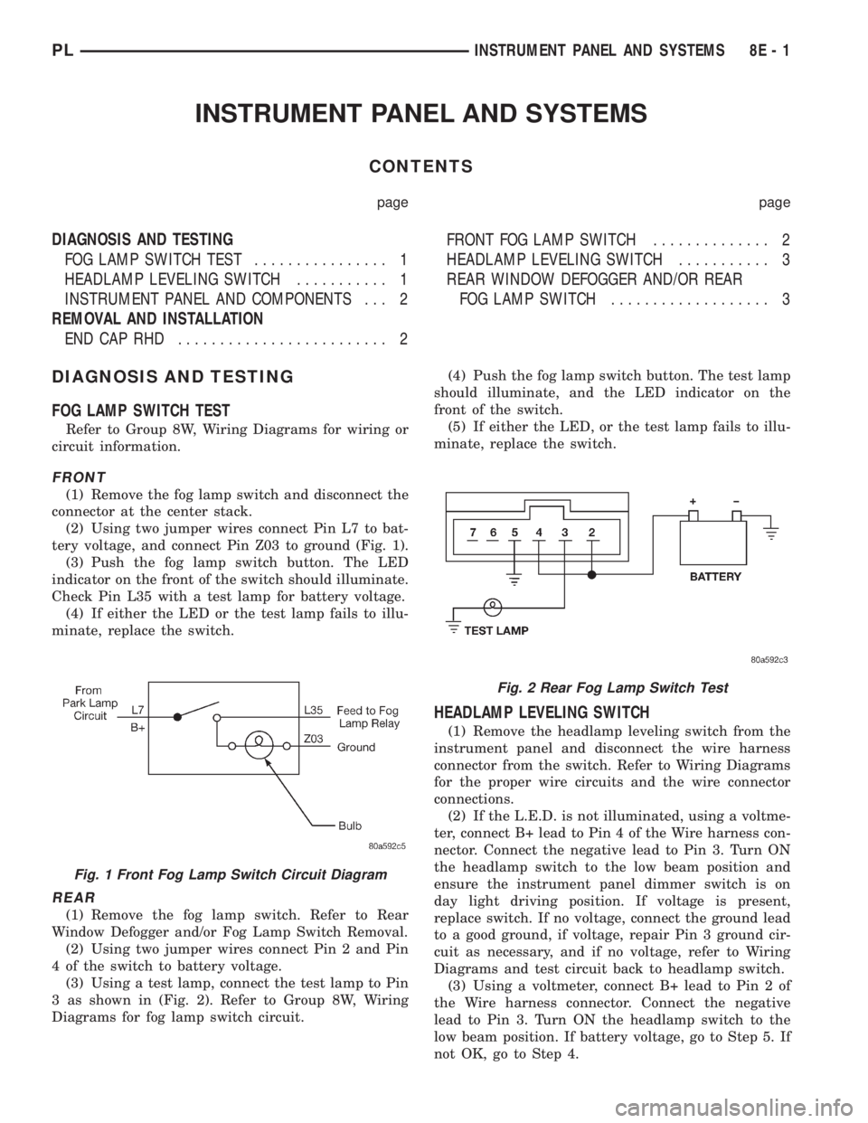
(2) Using two jumper wires connect Pin L7 to bat-
tery voltage, and connect Pin Z03 to ground (Fig. 1).
(3) Push the fog lamp switch button. The LED
indicator on the front of the switch should illuminate.
Check Pin L35 with a test lamp for battery voltage.
(4) If either the LED or the test lamp fails to illu-
minate, replace the switch.
REAR
(1) Remove the fog lamp switch. Refer to Rear
Window Defogger and/or Fog Lamp Switch Removal.
(2) Using two jumper wires connect Pin 2 and Pin
4 of the switch to battery voltage.
(3) Using a test lamp, connect the test lamp to Pin
3 as shown in (Fig. 2). Refer to Group 8W, Wiring
Diagrams for fog lamp switch circuit.(4) Push the fog lamp switch button. The test lamp
should illuminate, and the LED indicator on the
front of the switch.
(5) If either the LED, or the test lamp fails to illu-
minate, replace the switch.
HEADLAMP LEVELING SWITCH
(1) Remove the headlamp leveling switch from the
instrument panel and disconnect the wire harness
connector from the switch. Refer to Wiring Diagrams
for the proper wire circuits and the wire connector
connections.
(2) If the L.E.D. is not illuminated, using a voltme-
ter, connect B+ lead to Pin 4 of the Wire harness con-
nector. Connect the negative lead to Pin 3. Turn ON
the headlamp switch to the low beam position and
ensure the instrument panel dimmer switch is on
day light driving position. If voltage is present,
replace switch. If no voltage, connect the ground lead
to a good ground, if voltage, repair Pin 3 ground cir-
cuit as necessary, and if no voltage, refer to Wiring
Diagrams and test circuit back to headlamp switch.
(3) Using a voltmeter, connect B+ lead to Pin 2 of
the Wire harness connector. Connect the negative
lead to Pin 3. Turn ON the headlamp switch to the
low beam position. If battery voltage, go to Step 5. If
not OK, go to Step 4.
Fig. 1 Front Fog Lamp Switch Circuit Diagram
Fig. 2 Rear Fog Lamp Switch Test
PLINSTRUMENT PANEL AND SYSTEMS 8E - 1
Page 285 of 1200
(4) Connect the ground lead to a good ground, if no
voltage, refer to Wiring Diagrams and test circuit
back to headlamp switch. If battery voltage, repair
Pin 3 ground circuit as necessary.
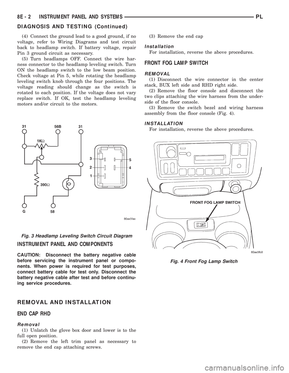
(5) Turn headlamps OFF. Connect the wire har-
ness connector to the headlamp leveling switch. Turn
ON the headlamp switch to the low beam position.
Check voltage at Pin 5, while rotating the headlamp
leveling switch knob through the four positions. The
voltage reading should change as the switch is
rotated to each position. If the voltage does not vary
replace switch. If OK, test the headlamp leveling
motors and/or circuit to the motors.
INSTRUMENT PANEL AND COMPONENTS
CAUTION: Disconnect the battery negative cable
before servicing the instrument panel or compo-
nents. When power is required for test purposes,
connect battery cable for test only. Disconnect the
battery negative cable after test and before continu-
ing service procedures.
REMOVAL AND INSTALLATION
END CAP RHD
Removal
(1) Unlatch the glove box door and lower is to the
full open position.
(2) Remove the left trim panel as necessary to
remove the end cap attaching screws.(3) Remove the end cap
Installation
For installation, reverse the above procedures.
FRONT FOG LAMP SWITCH
REMOVAL
(1) Disconnect the wire connector in the center
stack, BUX left side and RHD right side.
(2) Remove the floor console and disconnect the
two clips attaching the wire harness from the under-
side of the floor console.
(3) Remove the switch bezel and wiring harness
assembly from the floor console (Fig. 4).
INSTALLATION
For installation, reverse the above procedures.
Fig. 3 Headlamp Leveling Switch Circuit Diagram
Fig. 4 Front Fog Lamp Switch
8E - 2 INSTRUMENT PANEL AND SYSTEMSPL
DIAGNOSIS AND TESTING (Continued)
Page 290 of 1200
ANTENNA
The antenna has a short cable which connects into
the instrument panel harness. The connection is
made on the right side of the instrument panel.
Antenna performance may be tested by substitut-
ing a known good antenna. It is also possible to
check short or open circuits with an ohmmeter or
continuity light once the antenna cable is discon-
nected from the radio as follows:
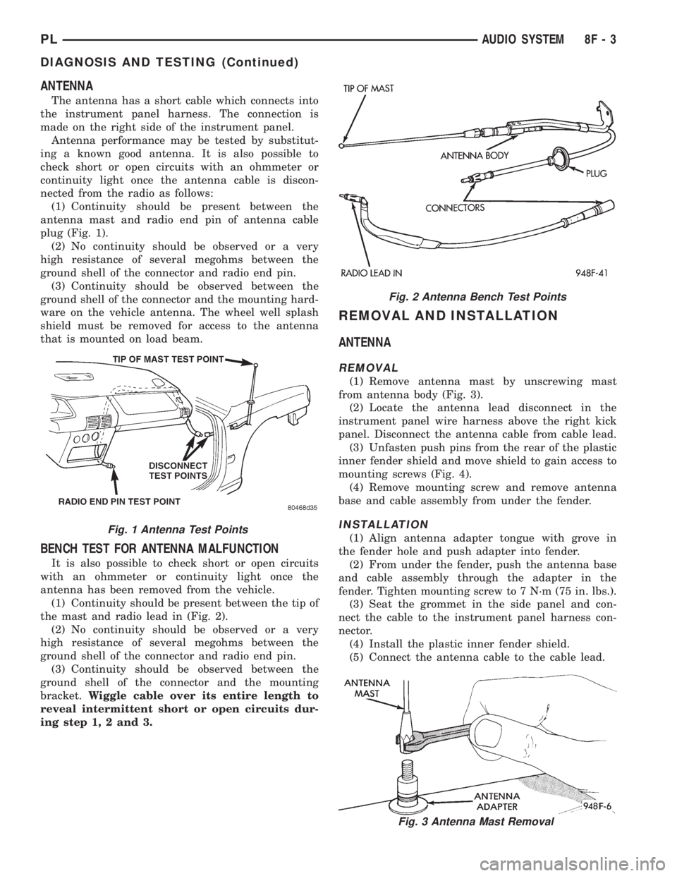
(1) Continuity should be present between the
antenna mast and radio end pin of antenna cable
plug (Fig. 1).
(2) No continuity should be observed or a very
high resistance of several megohms between the
ground shell of the connector and radio end pin.
(3) Continuity should be observed between the
ground shell of the connector and the mounting hard-
ware on the vehicle antenna. The wheel well splash
shield must be removed for access to the antenna
that is mounted on load beam.
BENCH TEST FOR ANTENNA MALFUNCTION
It is also possible to check short or open circuits
with an ohmmeter or continuity light once the
antenna has been removed from the vehicle.
(1) Continuity should be present between the tip of
the mast and radio lead in (Fig. 2).
(2) No continuity should be observed or a very
high resistance of several megohms between the
ground shell of the connector and radio end pin.
(3) Continuity should be observed between the
ground shell of the connector and the mounting
bracket.Wiggle cable over its entire length to
reveal intermittent short or open circuits dur-
ing step 1, 2 and 3.
REMOVAL AND INSTALLATION
ANTENNA
REMOVAL
(1) Remove antenna mast by unscrewing mast
from antenna body (Fig. 3).
(2) Locate the antenna lead disconnect in the
instrument panel wire harness above the right kick
panel. Disconnect the antenna cable from cable lead.
(3) Unfasten push pins from the rear of the plastic
inner fender shield and move shield to gain access to
mounting screws (Fig. 4).
(4) Remove mounting screw and remove antenna
base and cable assembly from under the fender.
INSTALLATION
(1) Align antenna adapter tongue with grove in
the fender hole and push adapter into fender.
(2) From under the fender, push the antenna base
and cable assembly through the adapter in the
fender. Tighten mounting screw to 7 N´m (75 in. lbs.).
(3) Seat the grommet in the side panel and con-
nect the cable to the instrument panel harness con-
nector.
(4) Install the plastic inner fender shield.
(5) Connect the antenna cable to the cable lead.
Fig. 2 Antenna Bench Test Points
Fig. 3 Antenna Mast Removal
Fig. 1 Antenna Test Points
PLAUDIO SYSTEM 8F - 3
DIAGNOSIS AND TESTING (Continued)
Page 311 of 1200
DIAGNOSIS AND TESTING
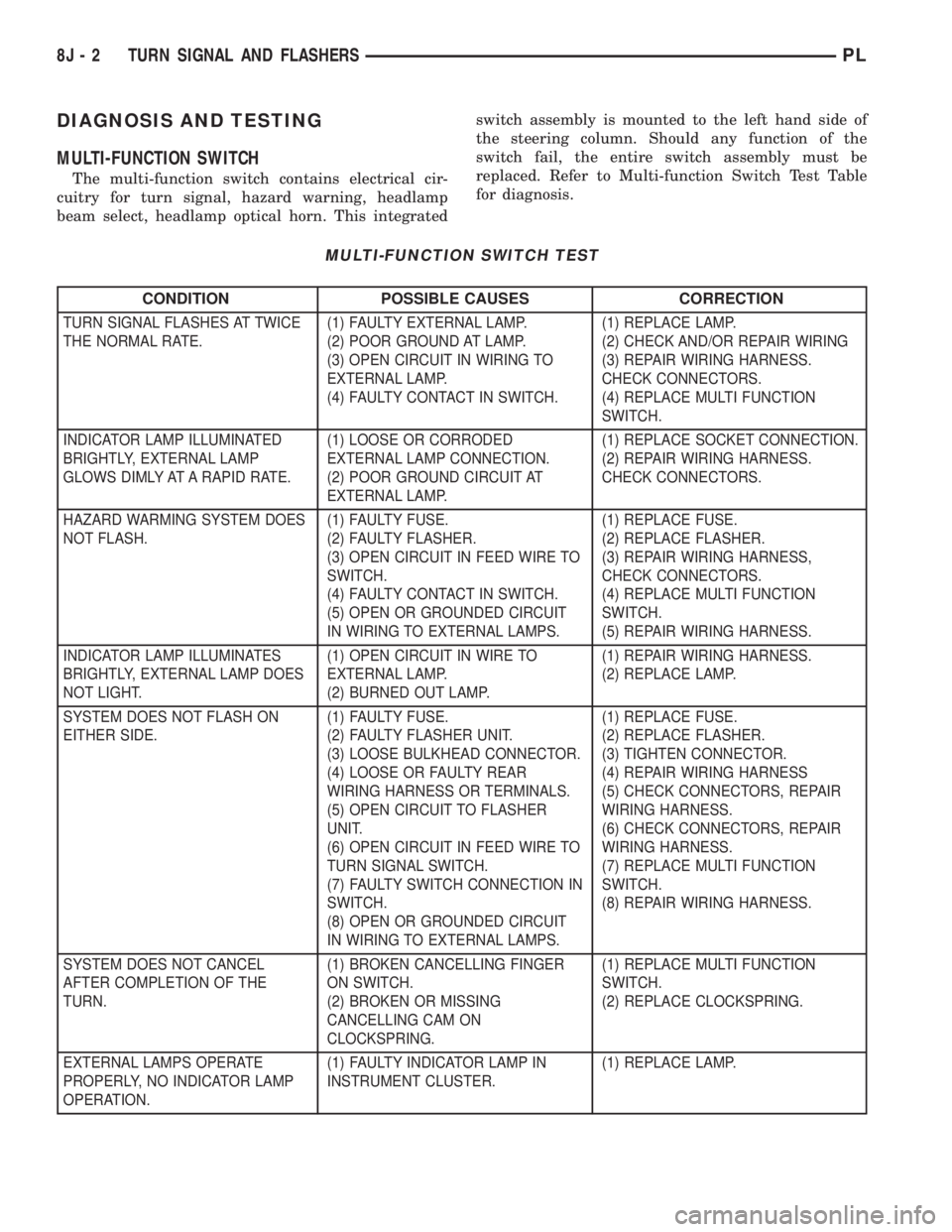
MULTI-FUNCTION SWITCH
The multi-function switch contains electrical cir-
cuitry for turn signal, hazard warning, headlamp
beam select, headlamp optical horn. This integratedswitch assembly is mounted to the left hand side of
the steering column. Should any function of the
switch fail, the entire switch assembly must be
replaced. Refer to Multi-function Switch Test Table
for diagnosis.
MULTI-FUNCTION SWITCH TEST
CONDITION POSSIBLE CAUSES CORRECTION
TURN SIGNAL FLASHES AT TWICE
THE NORMAL RATE.(1) FAULTY EXTERNAL LAMP.
(2) POOR GROUND AT LAMP.
(3) OPEN CIRCUIT IN WIRING TO
EXTERNAL LAMP.
(4) FAULTY CONTACT IN SWITCH.(1) REPLACE LAMP.
(2) CHECK AND/OR REPAIR WIRING
(3) REPAIR WIRING HARNESS.
CHECK CONNECTORS.
(4) REPLACE MULTI FUNCTION
SWITCH.
INDICATOR LAMP ILLUMINATED
BRIGHTLY, EXTERNAL LAMP
GLOWS DIMLY AT A RAPID RATE.(1) LOOSE OR CORRODED
EXTERNAL LAMP CONNECTION.
(2) POOR GROUND CIRCUIT AT
EXTERNAL LAMP.(1) REPLACE SOCKET CONNECTION.
(2) REPAIR WIRING HARNESS.
CHECK CONNECTORS.
HAZARD WARMING SYSTEM DOES
NOT FLASH.(1) FAULTY FUSE.
(2) FAULTY FLASHER.
(3) OPEN CIRCUIT IN FEED WIRE TO
SWITCH.
(4) FAULTY CONTACT IN SWITCH.
(5) OPEN OR GROUNDED CIRCUIT
IN WIRING TO EXTERNAL LAMPS.(1) REPLACE FUSE.
(2) REPLACE FLASHER.
(3) REPAIR WIRING HARNESS,
CHECK CONNECTORS.
(4) REPLACE MULTI FUNCTION
SWITCH.
(5) REPAIR WIRING HARNESS.
INDICATOR LAMP ILLUMINATES
BRIGHTLY, EXTERNAL LAMP DOES
NOT LIGHT.(1) OPEN CIRCUIT IN WIRE TO
EXTERNAL LAMP.
(2) BURNED OUT LAMP.(1) REPAIR WIRING HARNESS.
(2) REPLACE LAMP.
SYSTEM DOES NOT FLASH ON
EITHER SIDE.(1) FAULTY FUSE.
(2) FAULTY FLASHER UNIT.
(3) LOOSE BULKHEAD CONNECTOR.
(4) LOOSE OR FAULTY REAR
WIRING HARNESS OR TERMINALS.
(5) OPEN CIRCUIT TO FLASHER
UNIT.
(6) OPEN CIRCUIT IN FEED WIRE TO
TURN SIGNAL SWITCH.
(7) FAULTY SWITCH CONNECTION IN
SWITCH.
(8) OPEN OR GROUNDED CIRCUIT
IN WIRING TO EXTERNAL LAMPS.(1) REPLACE FUSE.
(2) REPLACE FLASHER.
(3) TIGHTEN CONNECTOR.
(4) REPAIR WIRING HARNESS
(5) CHECK CONNECTORS, REPAIR
WIRING HARNESS.
(6) CHECK CONNECTORS, REPAIR
WIRING HARNESS.
(7) REPLACE MULTI FUNCTION
SWITCH.
(8) REPAIR WIRING HARNESS.
SYSTEM DOES NOT CANCEL
AFTER COMPLETION OF THE
TURN.(1) BROKEN CANCELLING FINGER
ON SWITCH.
(2) BROKEN OR MISSING
CANCELLING CAM ON
CLOCKSPRING.(1) REPLACE MULTI FUNCTION
SWITCH.
(2) REPLACE CLOCKSPRING.
EXTERNAL LAMPS OPERATE
PROPERLY, NO INDICATOR LAMP
OPERATION.(1) FAULTY INDICATOR LAMP IN
INSTRUMENT CLUSTER.(1) REPLACE LAMP.
8J - 2 TURN SIGNAL AND FLASHERSPL
Page 313 of 1200
To test the switch, first disconnect the negative
battery cable, then remove the upper and lower col-
umn shrouds to gain access to the switch connector.
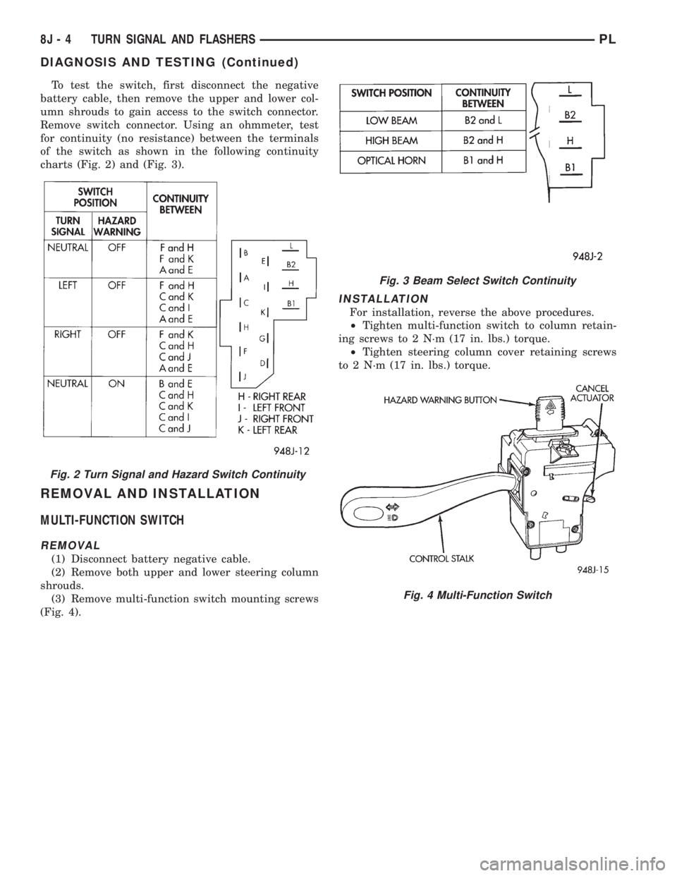
Remove switch connector. Using an ohmmeter, test
for continuity (no resistance) between the terminals
of the switch as shown in the following continuity
charts (Fig. 2) and (Fig. 3).
REMOVAL AND INSTALLATION
MULTI-FUNCTION SWITCH
REMOVAL
(1) Disconnect battery negative cable.
(2) Remove both upper and lower steering column
shrouds.
(3) Remove multi-function switch mounting screws
(Fig. 4).
INSTALLATION
For installation, reverse the above procedures.
²Tighten multi-function switch to column retain-
ing screws to 2 N´m (17 in. lbs.) torque.
²Tighten steering column cover retaining screws
to 2 N´m (17 in. lbs.) torque.
Fig. 2 Turn Signal and Hazard Switch Continuity
Fig. 3 Beam Select Switch Continuity
Fig. 4 Multi-Function Switch
8J - 4 TURN SIGNAL AND FLASHERSPL
DIAGNOSIS AND TESTING (Continued)