1999 DODGE NEON battery location
[x] Cancel search: battery locationPage 154 of 1200
ABS FUSES
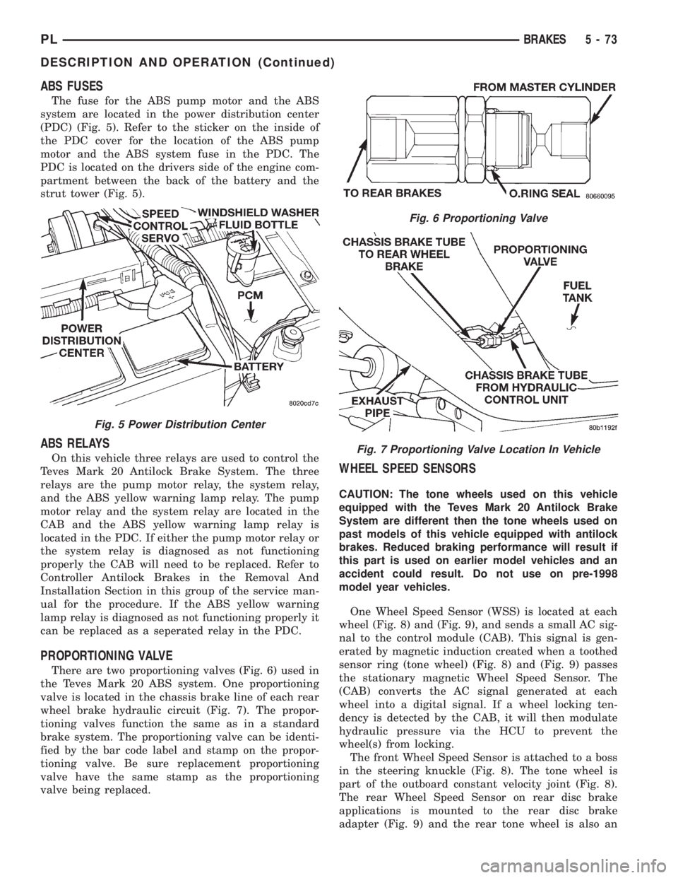
The fuse for the ABS pump motor and the ABS
system are located in the power distribution center
(PDC) (Fig. 5). Refer to the sticker on the inside of
the PDC cover for the location of the ABS pump
motor and the ABS system fuse in the PDC. The
PDC is located on the drivers side of the engine com-
partment between the back of the battery and the
strut tower (Fig. 5).
ABS RELAYS
On this vehicle three relays are used to control the
Teves Mark 20 Antilock Brake System. The three
relays are the pump motor relay, the system relay,
and the ABS yellow warning lamp relay. The pump
motor relay and the system relay are located in the
CAB and the ABS yellow warning lamp relay is
located in the PDC. If either the pump motor relay or
the system relay is diagnosed as not functioning
properly the CAB will need to be replaced. Refer to
Controller Antilock Brakes in the Removal And
Installation Section in this group of the service man-
ual for the procedure. If the ABS yellow warning
lamp relay is diagnosed as not functioning properly it
can be replaced as a seperated relay in the PDC.
PROPORTIONING VALVE
There are two proportioning valves (Fig. 6) used in
the Teves Mark 20 ABS system. One proportioning
valve is located in the chassis brake line of each rear
wheel brake hydraulic circuit (Fig. 7). The propor-
tioning valves function the same as in a standard
brake system. The proportioning valve can be identi-
fied by the bar code label and stamp on the propor-
tioning valve. Be sure replacement proportioning
valve have the same stamp as the proportioning
valve being replaced.
WHEEL SPEED SENSORS
CAUTION: The tone wheels used on this vehicle
equipped with the Teves Mark 20 Antilock Brake
System are different then the tone wheels used on
past models of this vehicle equipped with antilock
brakes. Reduced braking performance will result if
this part is used on earlier model vehicles and an
accident could result. Do not use on pre-1998
model year vehicles.
One Wheel Speed Sensor (WSS) is located at each
wheel (Fig. 8) and (Fig. 9), and sends a small AC sig-
nal to the control module (CAB). This signal is gen-
erated by magnetic induction created when a toothed
sensor ring (tone wheel) (Fig. 8) and (Fig. 9) passes
the stationary magnetic Wheel Speed Sensor. The
(CAB) converts the AC signal generated at each
wheel into a digital signal. If a wheel locking ten-
dency is detected by the CAB, it will then modulate
hydraulic pressure via the HCU to prevent the
wheel(s) from locking.
The front Wheel Speed Sensor is attached to a boss
in the steering knuckle (Fig. 8). The tone wheel is
part of the outboard constant velocity joint (Fig. 8).
The rear Wheel Speed Sensor on rear disc brake
applications is mounted to the rear disc brake
adapter (Fig. 9) and the rear tone wheel is also an
Fig. 5 Power Distribution Center
Fig. 6 Proportioning Valve
Fig. 7 Proportioning Valve Location In Vehicle
PLBRAKES 5 - 73
DESCRIPTION AND OPERATION (Continued)
Page 159 of 1200
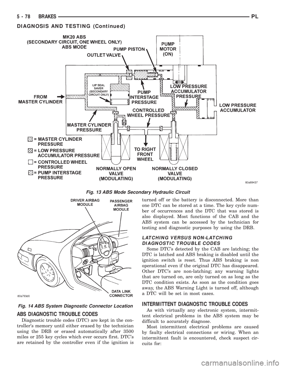
ABS DIAGNOSTIC TROUBLE CODES
Diagnostic trouble codes (DTC) are kept in the con-
troller's memory until either erased by the technician
using the DRB or erased automatically after 3500
miles or 255 key cycles which ever occurs first. DTC's
are retained by the controller even if the ignition isturned off or the battery is disconnected. More than
one DTC can be stored at a time. The key cycle num-
ber of occurrences and the DTC that was stored is
also displayed. Most functions of the CAB and the
ABS system can be accessed by the technician for
testing and diagnostic purposes by using the DRB.
LATCHING VERSUS NON-LATCHING
DIAGNOSTIC TROUBLE CODES
Some DTC's detected by the CAB are latching; the
DTC is latched and ABS braking is disabled until the
ignition switch is reset. Thus ABS braking is non
operational even if the original DTC has disappeared.
Other DTC's are non-latching; any warning lights
that are turned on, are only turned on as long as the
DTC condition exists. As soon as the condition goes
away, the ABS Warning Light is turned off, although
a DTC will be set in most cases.
INTERMITTENT DIAGNOSTIC TROUBLE CODES
As with virtually any electronic system, intermit-
tent electrical problems in the ABS system may be
difficult to accurately diagnose.
Most intermittent electrical problems are caused
by faulty electrical connections or wiring. When an
intermittent fault is encountered, check suspect cir-
cuits for:
Fig. 13 ABS Mode Secondary Hydraulic Circuit
Fig. 14 ABS System Diagnostic Connector Location
5 - 78 BRAKESPL
DIAGNOSIS AND TESTING (Continued)
Page 160 of 1200
A visual inspection for loose, disconnected, or mis-
routed wires should be done before attempting to
diagnose or service the ITT Teves Mark 20 antilock
brake system. A visual inspection will eliminate
unnecessary testing and diagnostics time. A thorough
visual inspection will include the following compo-
nents and areas of the vehicle.
(1) Inspect fuses in the power distribution center
(PDC) and the wiring junction block. Verify that all
fuses are fully inserted into the PDC and wring junc-
tion block. A label on the underside of the PDC cover
identifies the locations of the ABS fuses in the PDC.
(2) Inspect the 25-way electrical connector at the
CAB for damage, spread or backed-out wiring termi-
nals. Verify that the 25-way connector is fully
inserted in the socket on the CAB. Be sure that wires
are not stretched tight or pulled out of the connector.
(3) Verify that all the wheel speed sensor connec-
tions are secure.
(4) Poor mating of connector halves or terminals
not fully seated in the connector body.
(5) Improperly formed or damaged terminals. All
connector terminals in a suspect circuit should be
carefully reformed to increase contact tension.
(6) Poor terminal to wire connection. This requires
removing the terminal from the connector body to
inspect.
(7) Pin presence in the connector assembly
(8) Proper ground connections. Check all ground
connections for signs of corrosion, tight fasteners, or
other potential defects. Refer to wiring diagram man-
ual for ground locations.
(9) Problems with main power sources of the vehi-
cle. Inspect battery, generator, ignition circuits and
other related relays and fuses.
(10) If a visual check does not find the cause of the
problem, operate the car in an attempt to duplicate
the condition and record the trouble code.
(11) Most failures of the ABS system will disable
ABS function for the entire ignition cycle even if the
fault clears before key-off. There are some failure
conditions, however, which will allow ABS operation
to resume during the ignition cycle in which a failure
occurred if the failure conditions are no longer
present. The following conditions may result in inter-
mittent illumination of the ABS Warning Lamp. All
other failures will cause the lamp to remain on until
the ignition switch is turned off. Circuits involving
these inputs to the CAB should be investigated if a
complaint of intermittent warning system operation
is encountered.
(12) Low system voltage. If Low System Voltage is
detected by the CAB, the CAB will turn on the ABS
Warning Lamp until normal system voltage is
achieved. Once normal voltage is seen at the CAB,
normal operation resumes.(13) High system voltage. If high system voltage is
detected by the CAB, the CAB will turn on the
Amber ABS Warning Lamp until normal system volt-
age is achieved. Once normal voltage is again
detected by the CAB, normal ABS operation resumes.
(14) Additionally, any condition which results in
interruption of electrical current to the CAB or mod-
ulator assembly may cause the ABS Warning Lamp
to turn on intermittently.
(15) The body controller can turn on the (yellow)
ABS warning lamp if CCD communication between
the body controller and the CAB is interupted.
TONEWHEEL INSPECTION
CAUTION: The tone wheels used on this vehicle
equipped with the Teves Mark 20 Antilock Brake
System are different then those used on past mod-
els of this vehicle equipped with antilock brakes.
Reduced braking performance will result if this part
is used on earlier model vehicles and an accident
could result. Do not use on pre-1998 model year
vehicles.
Carefully inspect tonewheel at the suspected faulty
wheel speed sensor for missing, chipped or broken
teeth, this can cause erratic speed sensor signals.
Tonewheels should show no evidence of contact
with the wheel speed sensors. If contact was made,
determine cause and correct before replacing the
wheel speed sensor.
Excessive runout of the tonewheel can cause
erratic wheel speed sensor signals. Refer to Tone-
wheel Runout in the Specification Section in this sec-
tion of the service manual for the tonewheel runout
specification. Replace drive shaft assembly or rear
hub/bearing assembly if tonewheel runout exceeds
the specification.
Inspect tonewheels for looseness on their mounting
surfaces. Tonewheels are pressed onto their mounting
surfaces and should not rotate independently from
the mounting surface.
Check the wheel speed sensor head alignment to
the tone wheel. Also check the gap between the speed
sensor head and the tone wheel to ensure it is at
specification. Refer to Wheel Speed Sensor Clearance
in the Specification Section in this section of the ser-
vice manual.
PROPORTIONING VALVE
CAUTION: Proportioning valves should never be
disassembled.
If premature rear wheel skid occurs on a hard
brake application, it could be an indication that a
PLBRAKES 5 - 79
DIAGNOSIS AND TESTING (Continued)
Page 167 of 1200
(18) Install the wiring harness connector (Fig. 19)
on the speed control servo. Then install the routing
clip for the speed control servo wiring harness on the
speed control servo mounting bracket.
Install speed control servo mounting bracket on
body.
(19) Install and securely tighten the 2 bolts (Fig.
18) mounting the bracket for the speed control servo
to the body.
(20) Install the vacuum supply hose on the speed
control servo (Fig. 18).
(21) Install the power distribution center (PDC)
(Fig. 17) on the battery thermogaurd. PDC is install
by pushing straight down on it until the two retain-
ing clips holding it to the thermogaurd are latched to
the thermogaurd.
(22) Connect the negative (ground) cable on the
battery.
(23) Bleed the base brakes and the ABS brakes
hydraulic systems. Refer to Bleeding Base Brake
Hydraulic System in Service Procedures of the Base
Brake Section and Antilock Brakes Hydraulic System
Bleeding Procedure in Service Procedures of the
Antilock Brake Section for the required procedures.
(24) Fill the master cylinder to the proper fill
level.
(25) Road test vehicle to ensure proper operation
of the base and ABS brake systems.
PROPORTIONING VALVES
CAUTION: Proportioning valves should never be
disassembled.
REMOVE
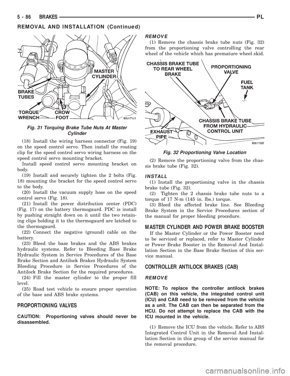
(1) Remove the chassis brake tube nuts (Fig. 32)
from the proportioning valve controlling the rear
wheel of the vehicle which has premature wheel skid.
(2) Remove the proportioning valve from the chas-
sis brake tube (Fig. 32).
INSTALL
(1) Install the proportioning valve in the chassis
brake tube (Fig. 32).
(2) Tighten the 2 chassis brake tube nuts to a
torque of 17 N´m (145 in. lbs.) torque.
(3) Bleed the affected brake line. See Bleeding
Brake System in the Service Procedures section of
the manual for proper bleeding procedure.
MASTER CYLINDER AND POWER BRAKE BOOSTER
If the Master Cylinder or the Power Booster need
to be serviced or replaced, refer to Master Cylinder
or Power Brake Booster in the Removal And Instal-
lation Section in the Base Brake Section of this ser-
vice manual.
CONTROLLER ANTILOCK BRAKES (CAB)
REMOVE
NOTE: To replace the controller antilock brakes
(CAB) on this vehicle, the integrated control unit
(ICU) and CAB need to be removed from the vehicle
as a unit. The CAB can then be separated from the
HCU. Do not attempt to replace the CAB with the
ICU mounted in the vehicle.
(1) Remove the ICU from the vehicle. Refer to ABS
Integrated Control Unit in the Removal And Instal-
lation Section in this group of the service manual for
the removal procedure.
Fig. 31 Torquing Brake Tube Nuts At Master
Cylinder
Fig. 32 Proportioning Valve Location
5 - 86 BRAKESPL
REMOVAL AND INSTALLATION (Continued)
Page 229 of 1200
To disable the ignition and fuel systems, disconnect
the Automatic Shutdown Relay (ASD). The ASD relay
is located in the Power Distribution Center (PDC).
Refer to the PDC cover for proper relay location.
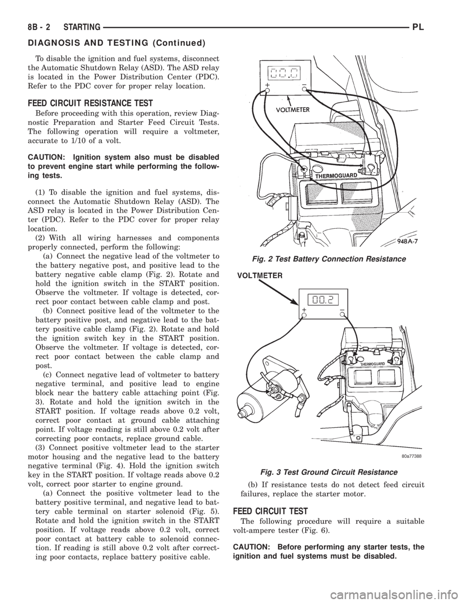
FEED CIRCUIT RESISTANCE TEST
Before proceeding with this operation, review Diag-
nostic Preparation and Starter Feed Circuit Tests.
The following operation will require a voltmeter,
accurate to 1/10 of a volt.
CAUTION: Ignition system also must be disabled
to prevent engine start while performing the follow-
ing tests.
(1) To disable the ignition and fuel systems, dis-
connect the Automatic Shutdown Relay (ASD). The
ASD relay is located in the Power Distribution Cen-
ter (PDC). Refer to the PDC cover for proper relay
location.
(2) With all wiring harnesses and components
properly connected, perform the following:
(a) Connect the negative lead of the voltmeter to
the battery negative post, and positive lead to the
battery negative cable clamp (Fig. 2). Rotate and
hold the ignition switch in the START position.
Observe the voltmeter. If voltage is detected, cor-
rect poor contact between cable clamp and post.
(b) Connect positive lead of the voltmeter to the
battery positive post, and negative lead to the bat-
tery positive cable clamp (Fig. 2). Rotate and hold
the ignition switch key in the START position.
Observe the voltmeter. If voltage is detected, cor-
rect poor contact between the cable clamp and
post.
(c) Connect negative lead of voltmeter to battery
negative terminal, and positive lead to engine
block near the battery cable attaching point (Fig.
3). Rotate and hold the ignition switch in the
START position. If voltage reads above 0.2 volt,
correct poor contact at ground cable attaching
point. If voltage reading is still above 0.2 volt after
correcting poor contacts, replace ground cable.
(3) Connect positive voltmeter lead to the starter
motor housing and the negative lead to the battery
negative terminal (Fig. 4). Hold the ignition switch
key in the START position. If voltage reads above 0.2
volt, correct poor starter to engine ground.
(a) Connect the positive voltmeter lead to the
battery positive terminal, and negative lead to bat-
tery cable terminal on starter solenoid (Fig. 5).
Rotate and hold the ignition switch in the START
position. If voltage reads above 0.2 volt, correct
poor contact at battery cable to solenoid connec-
tion. If reading is still above 0.2 volt after correct-
ing poor contacts, replace battery positive cable.(b) If resistance tests do not detect feed circuit
failures, replace the starter motor.
FEED CIRCUIT TEST
The following procedure will require a suitable
volt-ampere tester (Fig. 6).
CAUTION: Before performing any starter tests, the
ignition and fuel systems must be disabled.
Fig. 2 Test Battery Connection Resistance
Fig. 3 Test Ground Circuit Resistance
8B - 2 STARTINGPL
DIAGNOSIS AND TESTING (Continued)
Page 230 of 1200
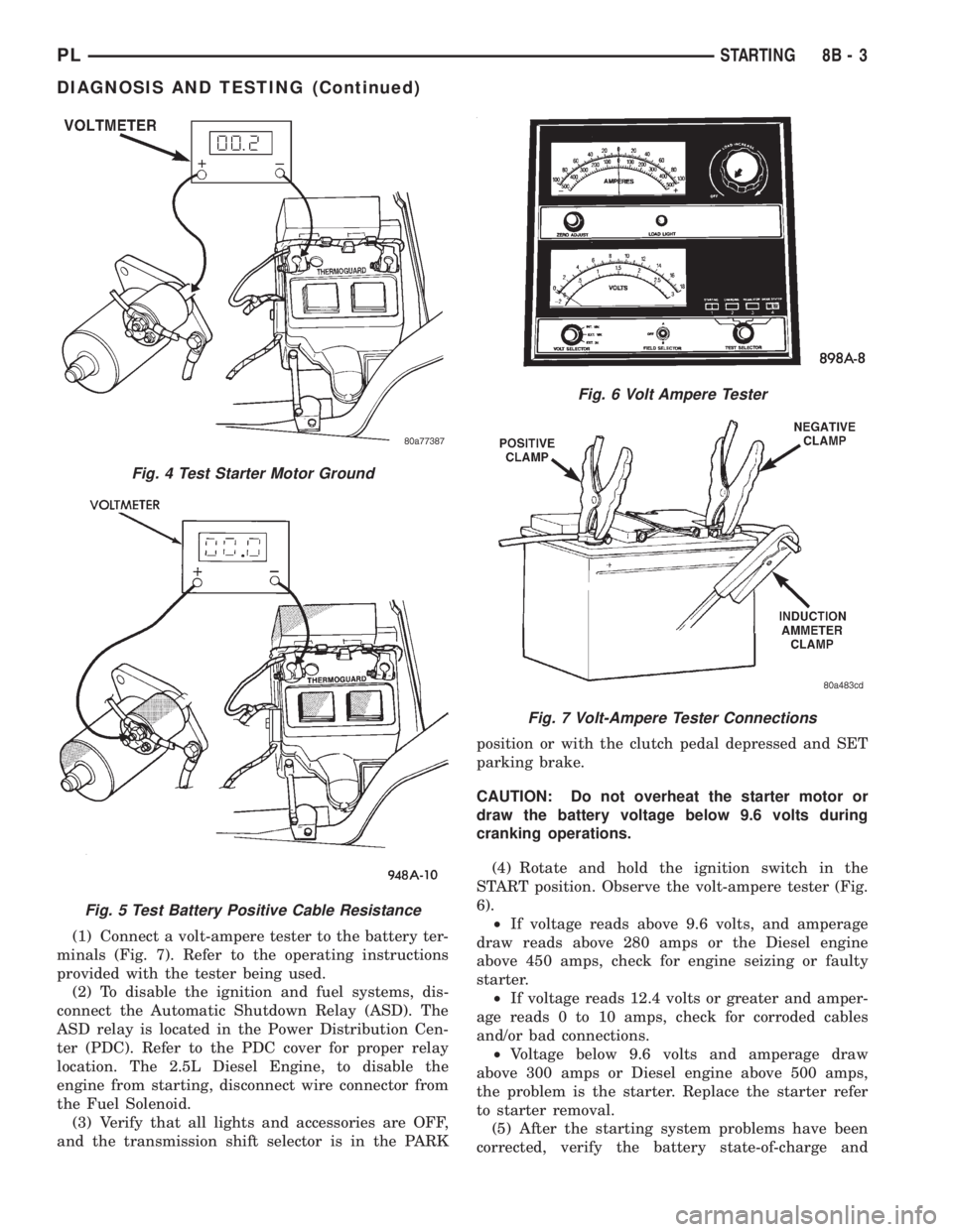
(1) Connect a volt-ampere tester to the battery ter-
minals (Fig. 7). Refer to the operating instructions
provided with the tester being used.
(2) To disable the ignition and fuel systems, dis-
connect the Automatic Shutdown Relay (ASD). The
ASD relay is located in the Power Distribution Cen-
ter (PDC). Refer to the PDC cover for proper relay
location. The 2.5L Diesel Engine, to disable the
engine from starting, disconnect wire connector from
the Fuel Solenoid.
(3) Verify that all lights and accessories are OFF,
and the transmission shift selector is in the PARKposition or with the clutch pedal depressed and SET
parking brake.
CAUTION: Do not overheat the starter motor or
draw the battery voltage below 9.6 volts during
cranking operations.
(4) Rotate and hold the ignition switch in the
START position. Observe the volt-ampere tester (Fig.
6).
²If voltage reads above 9.6 volts, and amperage
draw reads above 280 amps or the Diesel engine
above 450 amps, check for engine seizing or faulty
starter.
²If voltage reads 12.4 volts or greater and amper-
age reads 0 to 10 amps, check for corroded cables
and/or bad connections.
²Voltage below 9.6 volts and amperage draw
above 300 amps or Diesel engine above 500 amps,
the problem is the starter. Replace the starter refer
to starter removal.
(5) After the starting system problems have been
corrected, verify the battery state-of-charge and
Fig. 6 Volt Ampere Tester
Fig. 7 Volt-Ampere Tester Connections
Fig. 4 Test Starter Motor Ground
Fig. 5 Test Battery Positive Cable Resistance
PLSTARTING 8B - 3
DIAGNOSIS AND TESTING (Continued)
Page 234 of 1200
(7) Vehicles equipped with A/C:
(a) Using a floor jack or jack stand, raise the
engine and transmission assembly to the original
position.
(b) Install the front engine mount bolt through
the insulator and front crossmember mounting
bracket (Fig. 9).
(c) Tighten bolt to 54 N´m (40 ft. lbs.) torque.
(8) Lower vehicle and connect battery cables.
STARTER RELAY
The relay is located in the Power Distribution Cen-
ter (PDC). Refer to the PDC cover for relay location.
SPECIFICATIONS
STARTER
Engine should be up to operating temperature.
Extremely heavy oil or tight engine will increase
starter amperage draw.
TORQUE
DESCRIPTION TORQUE
Starter Mounting Bolts.........54N´m(40ft.lbs.)
Starter Solenoid Battery Nut. . . .10 N´m (90 in. lbs.)
Fig. 11 Wire Connection
Manufacturer BOSCH
Engine Application 2.0L OHC - DOHC
Power rating 0 .95 Kw
Voltage 12 VOLTS
No. of Fields 6
No. of Poles 6
Brushes 4
Drive Planetary Gear Train
Cranking Amperage Draw
test150 - 280 Amps.
PLSTARTING 8B - 7
REMOVAL AND INSTALLATION (Continued)
Page 242 of 1200
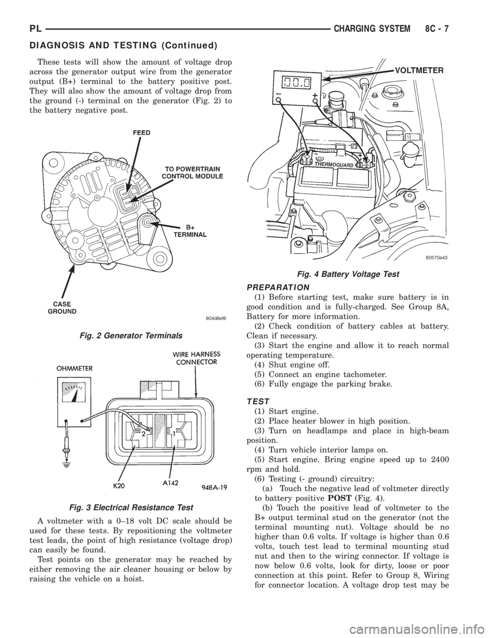
These tests will show the amount of voltage drop
across the generator output wire from the generator
output (B+) terminal to the battery positive post.
They will also show the amount of voltage drop from
the ground (-) terminal on the generator (Fig. 2) to
the battery negative post.
A voltmeter with a 0±18 volt DC scale should be
used for these tests. By repositioning the voltmeter
test leads, the point of high resistance (voltage drop)
can easily be found.
Test points on the generator may be reached by
either removing the air cleaner housing or below by
raising the vehicle on a hoist.
PREPARATION
(1) Before starting test, make sure battery is in
good condition and is fully-charged. See Group 8A,
Battery for more information.
(2) Check condition of battery cables at battery.
Clean if necessary.
(3) Start the engine and allow it to reach normal
operating temperature.
(4) Shut engine off.
(5) Connect an engine tachometer.
(6) Fully engage the parking brake.
TEST
(1) Start engine.
(2) Place heater blower in high position.
(3) Turn on headlamps and place in high-beam
position.
(4) Turn vehicle interior lamps on.
(5) Start engine. Bring engine speed up to 2400
rpm and hold.
(6) Testing (- ground) circuitry:
(a) Touch the negative lead of voltmeter directly
to battery positivePOST(Fig. 4).
(b) Touch the positive lead of voltmeter to the
B+ output terminal stud on the generator (not the
terminal mounting nut). Voltage should be no
higher than 0.6 volts. If voltage is higher than 0.6
volts, touch test lead to terminal mounting stud
nut and then to the wiring connector. If voltage is
now below 0.6 volts, look for dirty, loose or poor
connection at this point. Refer to Group 8, Wiring
for connector location. A voltage drop test may be
Fig. 2 Generator Terminals
Fig. 3 Electrical Resistance Test
Fig. 4 Battery Voltage Test
PLCHARGING SYSTEM 8C - 7
DIAGNOSIS AND TESTING (Continued)