1999 DODGE NEON manual transmission
[x] Cancel search: manual transmissionPage 4 of 1200
MAINTENANCE SCHEDULES
INDEX
page page
GENERAL INFORMATION
INTRODUCTION......................... 3
SCHEDULE ± A.......................... 3SCHEDULE ± B.......................... 4
UNSCHEDULED INSPECTION............... 3
GENERAL INFORMATION
INTRODUCTION
Service and maintenance procedures for compo-
nents and systems listed in Schedule ± A or B can be
found by using the Group Tab Locator index at the
front of this manual. If it is not clear which group
contains the information needed, refer to the index at
the back of this manual.
There are two maintenance schedules that show
proper service based on the conditions that the vehi-
cle is subjected to. Use the schedule that best
describes these conditions.
Schedule ±A, lists maintenance recommended for
vehicles used for general transportation.
Schedule ±B, lists maintenance recommended for
vehicles used under the following conditions:
²Frequent short trip driving less than 5 miles (8
km)
²Frequent driving in dusty conditions
²Frequent trailer towing
²Extensive idling
²More than 50% of your driving is at sustained
high speeds during hot weather, above 90ÉF (32ÉC)
Where time and mileage are listed, follow the
interval that occurs first.
EMISSION CONTROL SYSTEM MAINTENANCE
The scheduled emission maintenance listed inbold
typeon the Maintenance Schedules, must be done at
the mileage specified to assure the continued proper
functioning of the emission control system. These,
and all other maintenance services included in this
manual, should be done to provide the best vehicle
performance and reliability. More frequent mainte-
nance may be needed for vehicles in severe operating
conditions such as dusty areas and very short trip
driving.
UNSCHEDULED INSPECTION
At Each Stop For Fuel
²Check engine oil level, add as required.
²Check windshield washer solvent and add if
required.
Once A Month
²Check tire pressure and look for unusual wear
or damage.
²Inspect battery, clean, and tighten terminals as
required.
²Check fluid levels of coolant reservoir, power
steering and automatic transmission and add as
required.
²Check all lights and all other electrical items for
correct operation.
At Each Oil Change
²Inspect exhaust system.
²Inspect brake hoses.
²Inspect the CV joints and front suspension com-
ponents.
²Rotate the tires at each oil change interval
shown on Schedule ± A (7,500 miles) or every other
interval shown on schedule ± B (6,000 miles).
²Check coolant level, hoses and clamps.
²Check the manual transaxle fluid level.
²If the mileage is less than 7,500 miles (12 000
km) yearly, replace the engine oil filter at each oil
change.
SCHEDULE ± A
7,500 Miles (12 000 km) or at 6 months
²Change engine oil.
15,000 Miles (24 000 km) or at 12 months
²Change engine oil.
²Replace engine oil filter.
²Adjust drive belt tension.
22,500 Miles (36 000 km) or at 18 months
²Change engine oil.
²Inspect the front brake pads and rear brake lin-
ings.
30,000 Miles (48 000 km) or at 24 months
²Change engine oil.
²Replace engine oil filter.
²Lubricate front suspension ball joints.
²Adjust drive belt tension.
PLLUBRICATION AND MAINTENANCE 0 - 3
Page 8 of 1200
JUMP STARTING, TOWING AND HOISTING
INDEX
page page
SERVICE PROCEDURES
HOISTING RECOMMENDATIONS............ 9JUMP STARTING PROCEDURE.............. 7
TOWING RECOMMENDATIONS.............. 8
SERVICE PROCEDURES
JUMP STARTING PROCEDURE
WARNING: REVIEW ALL SAFETY PRECAUTIONS
AND WARNINGS IN GROUP 8A, BATTERY/START-
ING/CHARGING SYSTEMS DIAGNOSTICS. DO NOT
JUMP START A FROZEN BATTERY, PERSONAL
INJURY CAN RESULT. DO NOT JUMP START WHEN
MAINTENANCE FREE BATTERY INDICATOR DOT IS
YELLOW OR BRIGHT COLOR. DO NOT JUMP
START A VEHICLE WHEN THE BATTERY FLUID IS
BELOW THE TOP OF LEAD PLATES. DO NOT
ALLOW JUMPER CABLE CLAMPS TO TOUCH
EACH OTHER WHEN CONNECTED TO A BOOSTER
SOURCE. DO NOT USE OPEN FLAME NEAR BAT-
TERY. REMOVE METALLIC JEWELRY WORN ON
HANDS OR WRISTS TO AVOID INJURY BY ACCI-
DENTAL ARCING OF BATTERY CURRENT. WHEN
USING A HIGH OUTPUT BOOSTING DEVICE, DO
NOT ALLOW BATTERY VOLTAGE TO EXCEED 16
VOLTS. REFER TO INSTRUCTIONS PROVIDED
WITH DEVICE BEING USED.
CAUTION: When using another vehicle as a
booster, do not allow vehicles to touch. Electrical
systems can be damaged on either vehicle.
TO JUMP START A DISABLED VEHICLE:
(1) Raise hood on disabled vehicle and visually
inspect engine compartment for:
²Battery cable clamp condition, clean if necessary.
²Frozen battery.
²Yellow or bright color test indicator, if equipped.
²Low battery fluid level.
²Generator drive belt condition and tension.
²Fuel fumes or leakage, correct if necessary.
CAUTION: If the cause of starting problem on dis-
abled vehicle is severe, damage to booster vehicle
charging system can result.
(2) When using another vehicle as a booster
source, park the booster vehicle within cable reach.
Turn off all accessories, set the parking brake, placethe automatic transmission in PARK or the manual
transmission in NEUTRAL and turn the ignition
OFF.
(3) On disabled vehicle, place gear selector in park
or neutral and set park brake. Turn off all accesso-
ries.
(4) Connect jumper cables to booster battery. RED
clamp to positive terminal (+). BLACK clamp to neg-
ative terminal (-). DO NOT allow clamps at opposite
end of cables to touch, electrical arc will result.
Review all warnings in this procedure.
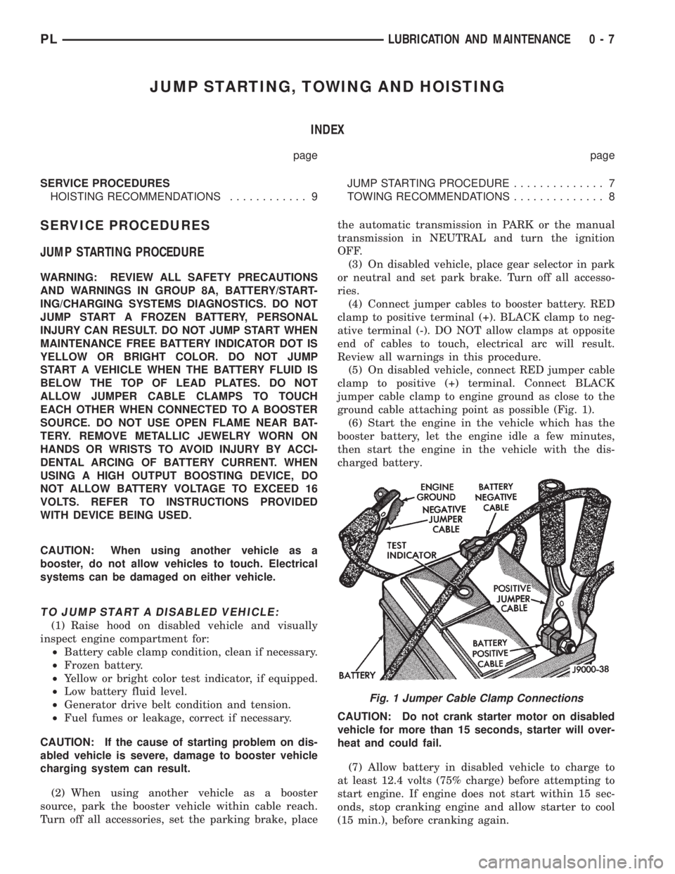
(5) On disabled vehicle, connect RED jumper cable
clamp to positive (+) terminal. Connect BLACK
jumper cable clamp to engine ground as close to the
ground cable attaching point as possible (Fig. 1).
(6) Start the engine in the vehicle which has the
booster battery, let the engine idle a few minutes,
then start the engine in the vehicle with the dis-
charged battery.
CAUTION: Do not crank starter motor on disabled
vehicle for more than 15 seconds, starter will over-
heat and could fail.
(7) Allow battery in disabled vehicle to charge to
at least 12.4 volts (75% charge) before attempting to
start engine. If engine does not start within 15 sec-
onds, stop cranking engine and allow starter to cool
(15 min.), before cranking again.
Fig. 1 Jumper Cable Clamp Connections
PLLUBRICATION AND MAINTENANCE 0 - 7
Page 66 of 1200
DIFFERENTIAL AND DRIVELINE
CONTENTS
page page
GENERAL INFORMATION
FRONT DRIVESHAFTS.................... 1
DIAGNOSIS AND TESTING
DRIVESHAFT DIAGNOSIS.................. 2
REMOVAL AND INSTALLATION
FRONT DRIVESHAFTS.................... 2
DISASSEMBLY AND ASSEMBLY
DRIVESHAFT RECONDITION............... 7INNER TRIPOD JOINT SEAL BOOT.......... 9
OUTER C/V JOINT SEAL BOOT............ 13
SPECIFICATIONS
TORQUE.............................. 16
SPECIAL TOOLS
DRIVESHAFT........................... 16
GENERAL INFORMATION
FRONT DRIVESHAFTS
Vehicles equipped with either an automatic or
manual transmission use the unequal±length drive-
shaft system.
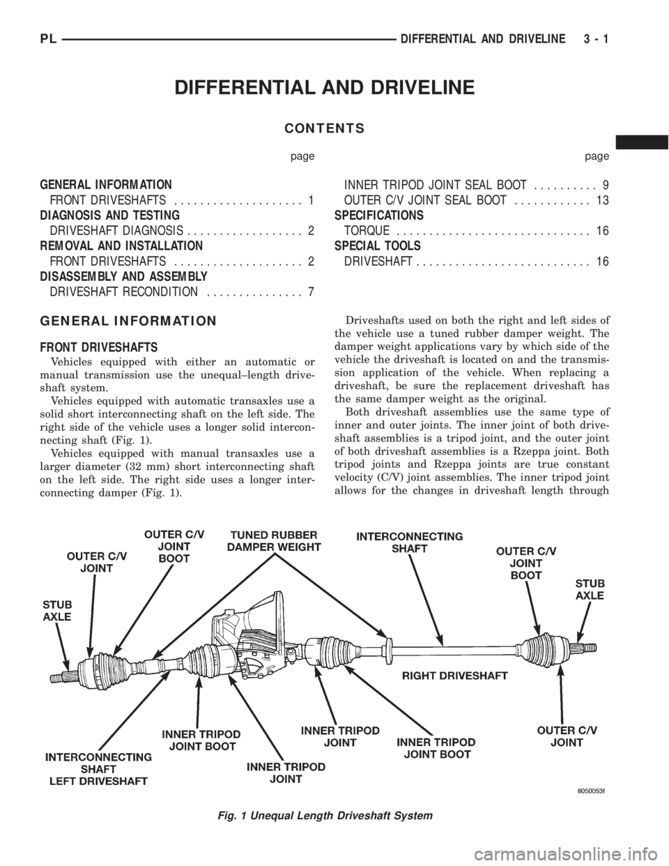
Vehicles equipped with automatic transaxles use a
solid short interconnecting shaft on the left side. The
right side of the vehicle uses a longer solid intercon-
necting shaft (Fig. 1).
Vehicles equipped with manual transaxles use a
larger diameter (32 mm) short interconnecting shaft
on the left side. The right side uses a longer inter-
connecting damper (Fig. 1).Driveshafts used on both the right and left sides of
the vehicle use a tuned rubber damper weight. The
damper weight applications vary by which side of the
vehicle the driveshaft is located on and the transmis-
sion application of the vehicle. When replacing a
driveshaft, be sure the replacement driveshaft has
the same damper weight as the original.
Both driveshaft assemblies use the same type of
inner and outer joints. The inner joint of both drive-
shaft assemblies is a tripod joint, and the outer joint
of both driveshaft assemblies is a Rzeppa joint. Both
tripod joints and Rzeppa joints are true constant
velocity (C/V) joint assemblies. The inner tripod joint
allows for the changes in driveshaft length through
Fig. 1 Unequal Length Driveshaft System
PLDIFFERENTIAL AND DRIVELINE 3 - 1
Page 177 of 1200
DRIVE PLATE MISALIGNMENT
Common causes of misalignment are:
²Heat warping
²Mounting drive plate on a dirty crankshaft
flange
²Incorrect bolt tightening
²Improper seating on the crankshaft shoulder
²Loose crankshaft bolts
Clean the crankshaft flange before mounting the
drive plate. Dirt and grease on the flange surface
may misalign the flywheel, causing excessive runout.
Use new bolts when mounting drive plate to crank-
shaft. Tighten drive plate bolts to specified torque
only. Over-tightening can distort the drive plate hub
causing excessive runout.
CLUTCH COVER AND DISC RUNOUT
Check condition of the clutch cover before installa-
tion. A warped cover or diaphragm spring will cause
grab and/or incomplete release or engagement. Use
care when handling the clutch assembly. Impact can
distort the cover, diaphragm spring, and release fin-
gers.
CLUTCH CHATTER COMPLAINTS
For all clutch chatter complaints, do the following:
(1) Check for loose, misaligned, or broken engine
and transmission mounts. If present, they should be
corrected at this time. Test vehicle for chatter. If
chatter is gone, there is no need to go any further. If
chatter persists:
(2) Check to see if clutch cable routing is correct
and operates smoothly.
(3) Check for loose connections in drive train. Cor-
rect any problems and determine if clutch chatter
complaints have been satisfied. If not:
(4) Remove transaxle. See Group 21, Manual Tran-
saxle for procedure.
(5) Check to see if the release bearing is sticky or
binding. Replace bearing, if needed.
(6) Check linkage for excessive wear on the pivot
stud and fork fingers. Replace all worn parts.
(7) Check clutch assembly for contamination (dirt,
oil). Replace clutch assembly, if required.
(8) Check to see if the clutch disc hub splines are
damaged. Replace with new clutch assembly, if nec-
essary.
(9) Check input shaft splines for damage. Replace,
if necessary.
(10) Check for uneven wear on clutch fingers.
(11) Check for broken clutch cover diaphragm
spring fingers. Replace with new clutch assembly, if
necessary.
CLASH±INTO±REVERSE COMPLAINTS
Certain NV T350 (A-578) manual transaxles are
equipped with a reverse brake. It prevents clash
when shifting into reverse, but only if the vehicle is
not moving. See Group 21, Transaxle for further
diagnosis.
(1) Depress clutch pedal to floor and hold. After
three seconds, shift to reverse. If clash is present,
clutch has excessive spin time, and the reverse brake
may not be functioning.
(2) Remove transaxle. See Group 21, Manual Tran-
saxle for procedure.
(3) Check the input shaft spline, clutch disc
splines, and release bearing for dry rust. If present,
clean rust off and apply a light coat of bearing grease
to the input shaft splines. Apply grease on the input
shaft splines only where the clutch disc slides. Verify
that the clutch disc slides freely along the input shaft
spline.
(4) Check to see if the clutch disc hub splines are
damaged, and replace with new clutch assembly if
required.
(5) Check the input shaft for damaged splines.
Replace as necessary.
(6) Check for broken clutch cover diaphragm
spring fingers.
(7) Install clutch assembly and transaxle.
REMOVAL AND INSTALLATION
CLUTCH CABLE
REMOVAL
(1) Pull up and remove Power Distribution Center.
(2) Remove clutch cable inspection cover.
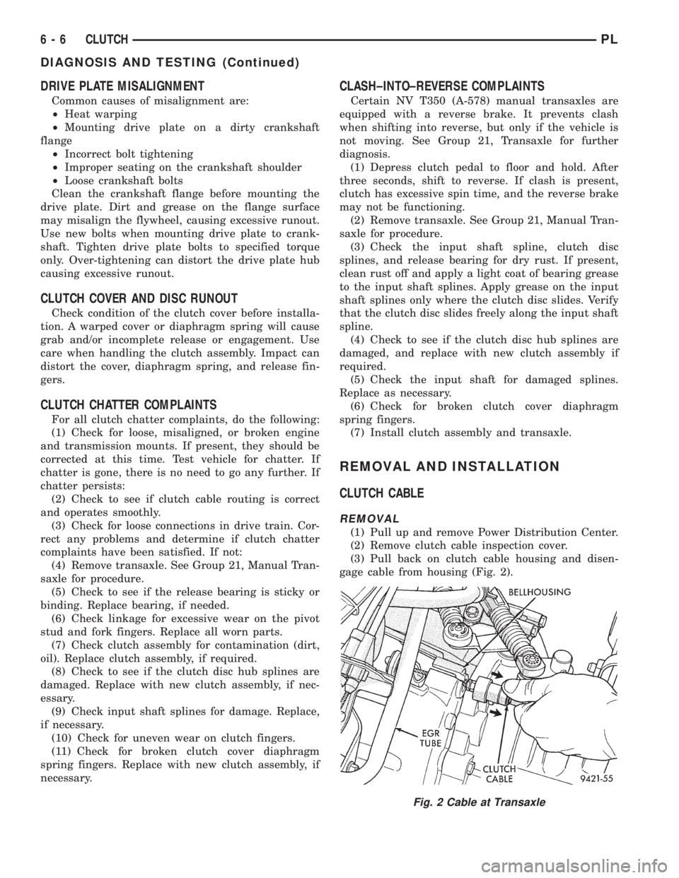
(3) Pull back on clutch cable housing and disen-
gage cable from housing (Fig. 2).
Fig. 2 Cable at Transaxle
6 - 6 CLUTCHPL
DIAGNOSIS AND TESTING (Continued)
Page 228 of 1200
STARTING
CONTENTS
page page
GENERAL INFORMATION
BOSCH STARTER........................ 1
INTRODUCTION......................... 1
SUPPLY CIRCUIT AND CONTROL CIRCUIT.... 1
DIAGNOSIS AND TESTING
FEED CIRCUIT RESISTANCE TEST........... 2
FEED CIRCUIT TEST...................... 2
STARTER CONTROL CIRCUIT.............. 1STARTING SYSTEM TEST................. 4
REMOVAL AND INSTALLATION
SAFETY SWITCHES...................... 6
STARTER RELAY........................ 7
STARTER .............................. 6
SPECIFICATIONS
STARTER .............................. 7
TORQUE............................... 7
GENERAL INFORMATION
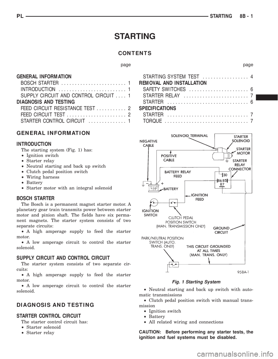
INTRODUCTION
The starting system (Fig. 1) has:
²Ignition switch
²Starter relay
²Neutral starting and back up switch
²Clutch pedal position switch
²Wiring harness
²Battery
²Starter motor with an integral solenoid
BOSCH STARTER
The Bosch is a permanent magnet starter motor. A
planetary gear train transmits power between starter
motor and pinion shaft. The fields have six perma-
nent magnets. The starter system consists of two
separate circuits:
²A high amperage supply to feed the starter
motor.
²A low amperage circuit to control the starter
solenoid.
SUPPLY CIRCUIT AND CONTROL CIRCUIT
The starter system consists of two separate cir-
cuits:
²A high amperage supply to feed the starter
motor.
²A low amperage circuit to control the starter
solenoid.
DIAGNOSIS AND TESTING
STARTER CONTROL CIRCUIT
The starter control circuit has:
²Starter solenoid
²Starter relay²Neutral starting and back up switch with auto-
matic transmissions
²Clutch pedal position switch with manual trans-
mission
²Ignition switch
²Battery
²All related wiring and connections
CAUTION: Before performing any starter tests, the
ignition and fuel systems must be disabled.
Fig. 1 Starting System
PLSTARTING 8B - 1
Page 275 of 1200

(8) If all tests performed test good, replace the dial
and gauge assembly.
(9) If the tachometer continues to be inoperative,
replace the print circuit board.
TEMPERATURE GAUGE
(1) Disconnect the coolant temperature sensor
(Fig. 12).
(2) Turn ignition switch ON. The temperature
gauge should be at its lowest position. Turn ignition
switch OFF.
(3) Ground temperature gauge sending unit con-
nector Pin 3. Refer to Group 8W, wiring Diagrams.
Turn ignition switch ON. The temperature gauge
should be at its highest position. After the seat belt
lamp goes out, the cluster should chime for about
eight seconds.
(a) If OK, check temperature sending unit con-
nector for proper connection. If connections are OK,
replace the sending unit.
(b) If not OK, and the high temperature chime
sounds but the gauge shows cold, replace the gauge
assembly. If gauge is still not working, replace the
printed circuit board.
SPEEDOMETER SYSTEM
The vehicle is equipped with a electronically driven
speedometer and odometer assemblies. A signal is
sent from a transmission-mounted vehicle speed sen-
sor to the speedometer circuitry through the wiring
harness.
SEAT BELT REMINDER SYSTEM TEST
For testing of this system refer to Group 8U,
Chime Warning/Reminder Systems.
SENDING UNIT
When a problem occurs with a cluster gauge check
for a defective sending unit or wiring. Do this before
disassembling the cluster.(1) Sending units and wiring can be checked by
grounding the connector leads at the sending unit in
the vehicle.
(2) With the ignition in the ON position, a
grounded input will cause the fuel or temperature
gauge to read at or above maximum.
SERVICE ENGINE SOON INDICATOR
Refer to Group 25, Emission Control Systems for
procedures.
VEHICLE SPEED SENSOR TEST
To test the vehicle speed sensor and related compo-
nents use a scan tool (DRB), and refer to the appro-
priate Powertrain Diagnostics Test Procedure
Manual.
REMOVAL AND INSTALLATION
ASH RECEIVER RETAINER AND LAMP
REMOVAL
(1) Open up and remove the ash receiver recepta-
cle.
(2) Remove the center bezel.
(3) Remove the two ash receiver retainer attaching
screws from the upper-rearward face and remove
retainer.
(4) For lamp replacement, remove the clamp and
lamp hood from the top of the retainer. Remove the
wiring clip at the forward edge of the retainer and
remove the lamp socket from the hood and replace
lamp.
INSTALLATION
For installation reverse the above procedures.
When installing the retainer ensure that the forward
tabs are inserted properly into the slots in the instru-
ment panel.
CENTER BEZEL
REMOVAL
(1) Open the ash receiver receptacle.
(2) Grasp the bezel and pull rearward disengaging
the clips.
INSTALLATION
For installation, reverse the above procedures.
CIGAR LIGHTER RECEPTACLE
REMOVAL
(1) Remove the cigar lighter element.
(2) Reach underneath the instrument panel
through the bottom access hole and disconnect the
cigar lighter receptacle wiring connectors.
Fig. 12 Engine Coolant Temperature Sensor
8E - 6 INSTRUMENT PANEL AND SYSTEMSPL
DIAGNOSIS AND TESTING (Continued)
Page 282 of 1200
the panel rearward to disengage the three locator
pins and remove.
(6) Reach in and disconnect the wiring connector(s)
for the rear window defogger and/or fog lamp
switch(s) as required.
INSTALLATION
For installation, reverse the above procedures.
SHIFTER KNOB
AUTOMATIC TRANSMISSION SHIFTER
REMOVAL
(1) Loosen the set screw at the left side under the
button area.
(2) Pull up until the knob slides off the shifter
shaft.
INSTALLATION
For installation, reverse the above procedures.
MANUAL TRANSMISSION SHIFTER
REMOVAL
(1) Pull the top part of the boot down until the two
tabs at the bottom of the knob are exposed.
(2) Release the locking tabs from the pins on the
shifter shaft.
(3) Pull up until the knob slides off the shifter
shaft.INSTALLATION
For installation, reverse the above procedures.
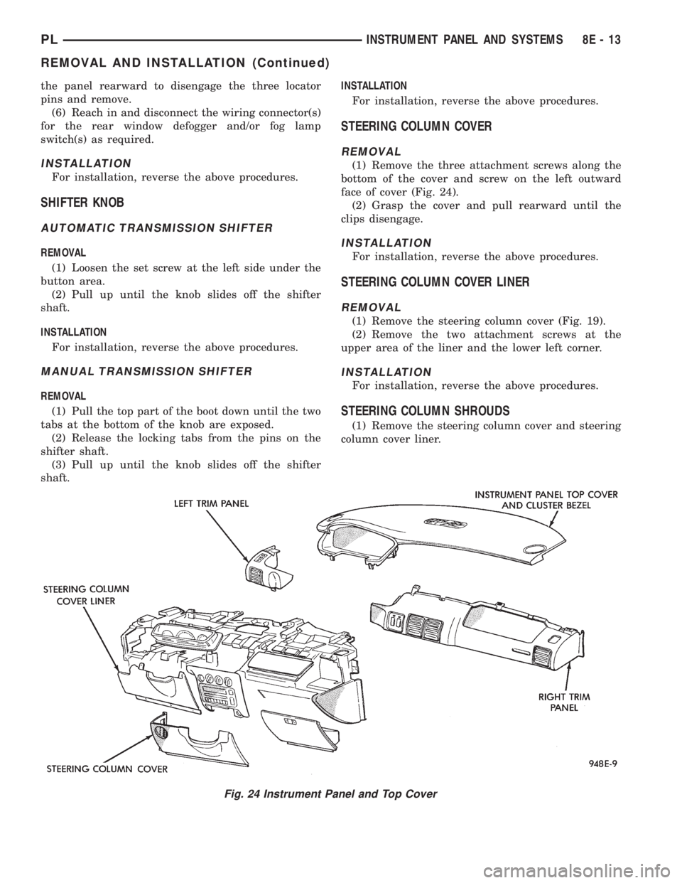
STEERING COLUMN COVER
REMOVAL
(1) Remove the three attachment screws along the
bottom of the cover and screw on the left outward
face of cover (Fig. 24).
(2) Grasp the cover and pull rearward until the
clips disengage.
INSTALLATION
For installation, reverse the above procedures.
STEERING COLUMN COVER LINER
REMOVAL
(1) Remove the steering column cover (Fig. 19).
(2) Remove the two attachment screws at the
upper area of the liner and the lower left corner.
INSTALLATION
For installation, reverse the above procedures.
STEERING COLUMN SHROUDS
(1) Remove the steering column cover and steering
column cover liner.
Fig. 24 Instrument Panel and Top Cover
PLINSTRUMENT PANEL AND SYSTEMS 8E - 13
REMOVAL AND INSTALLATION (Continued)
Page 299 of 1200
SPEED CONTROL SWITCHES
There are two separate switch pods that operate
the speed control system. The steering-wheel-
mounted switches use multiplexed circuits to provide
inputs to the PCM for ON, OFF, RESUME, ACCEL-
ERATE, SET, DECEL and CANCEL modes. Refer to
the owner's manual for more information on speed
control switch functions and setting procedures.When speed control is selected by depressing the
ON switch, the PCM allows a set speed to be stored
in RAM for speed control. To store a set speed,
depress the SET switch while the vehicle is moving
at a speed between 30 and 85 mph. In order for the
speed control to engage, the brakes cannot be
applied, nor can the gear selector be indicating the
transmission is in Park or Neutral.
The speed control can be disengaged manually by:
²Stepping on the brake pedal
²Depressing the OFF switch
²Depressing the CANCEL switch.
NOTE: Depressing the OFF switch or turning off
the ignition switch will erase the set speed stored
in the PCM.
For added safety,the speed control system is pro-
grammed to disengaged for any of the following con-
ditions:
²An indication of Park or Neutral
²An rpm increase without a VSS signal increase
(indicates that the clutch has been disengaged)
²Excessive engine rpm (indicates that the trans-
mission may be in a low gear)
²The VSS signal increases at a rate of 10 mph
per second (indicates that the co-efficient of friction
between the road surface and tires is extremely low)
²The VSS signal decreases at a rate of 10 mph
per second (indicates that the vehicle may have
decelerated at an extremely high rate)
²If the actual speed is not within 20 mph of the
set speed
The previous disengagement conditions are pro-
grammed for added safety.
Once the speed control has been disengaged,
depressing the ACCEL switch when speed is greater
than 25 mph restores the vehicle to the target speed
that was stored in the PCM.
NOTE: Depressing the OFF switch will erase the
set speed stored in the PCM's RAM.
While the speed control is engaged, the driver can
increase the vehicle speed by depressing the ACCEL
switch. The new target speed is stored in the PCM
when the ACCEL is released. The PCM also has a
9tap-up9feature in which vehicle speed increases at a
rate of approximately 2 mph for each momentary
switch activation of the ACCEL switch. The PCM
also provides a means to decelerate without disen-
gaging speed control. To decelerate from an existing
recorded target speed, depress and hold the COAST
switch until the desired speed is reached, then
release the switch.
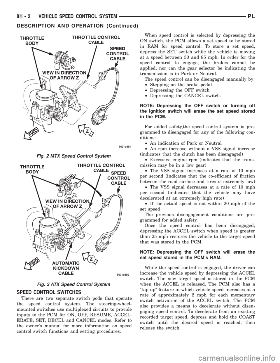
Fig. 2 MTX Speed Control System
Fig. 3 ATX Speed Control System
8H - 2 VEHICLE SPEED CONTROL SYSTEMPL
DESCRIPTION AND OPERATION (Continued)