1999 DODGE NEON seat adjustment
[x] Cancel search: seat adjustmentPage 24 of 1200
COMPETITION PACKAGE SUSPENSION
On vehicles that are equipped with the optional
competition package, special front struts are used.
The front struts used on a vehicle equipped with
the competition package are adjustable. The adjust-
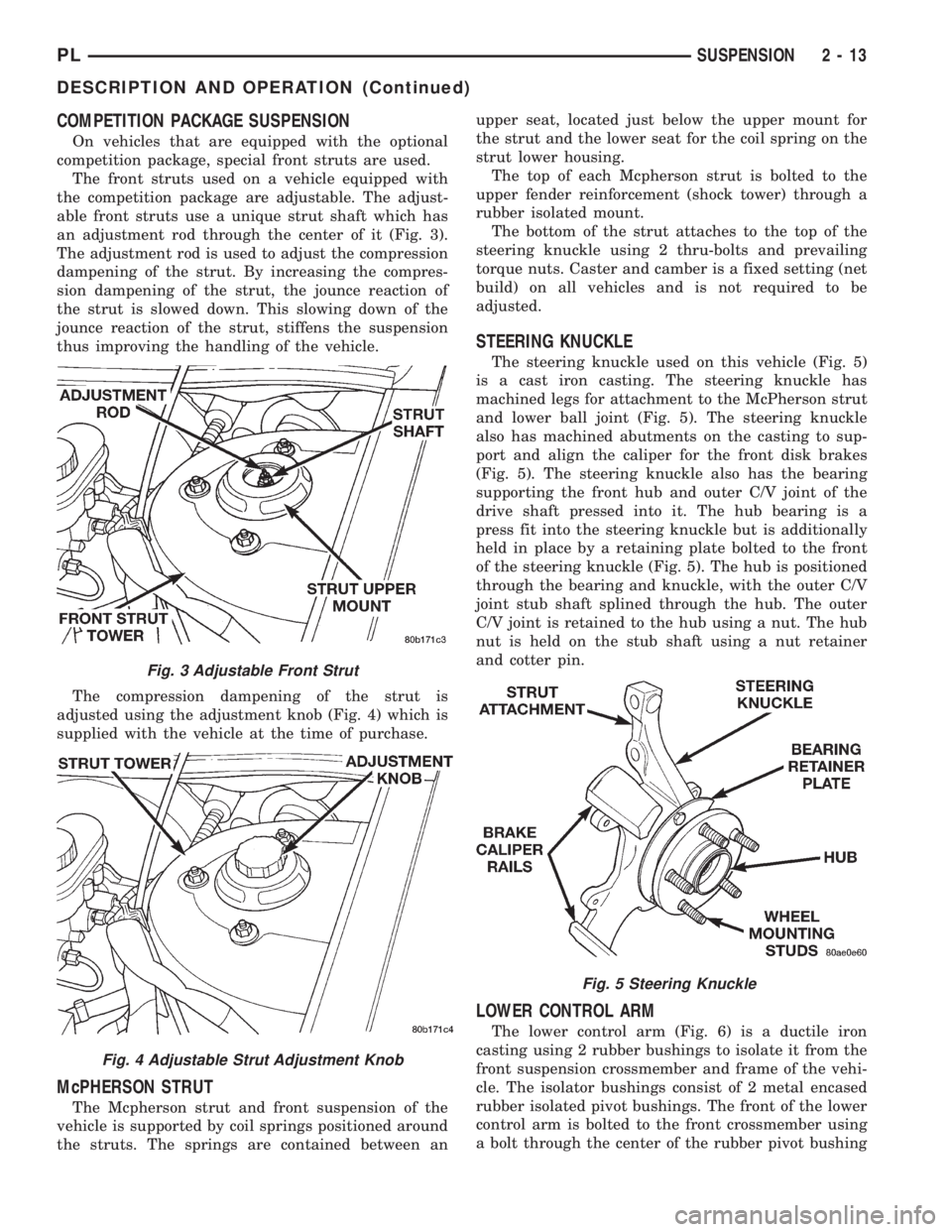
able front struts use a unique strut shaft which has
an adjustment rod through the center of it (Fig. 3).
The adjustment rod is used to adjust the compression
dampening of the strut. By increasing the compres-
sion dampening of the strut, the jounce reaction of
the strut is slowed down. This slowing down of the
jounce reaction of the strut, stiffens the suspension
thus improving the handling of the vehicle.
The compression dampening of the strut is
adjusted using the adjustment knob (Fig. 4) which is
supplied with the vehicle at the time of purchase.
McPHERSON STRUT
The Mcpherson strut and front suspension of the
vehicle is supported by coil springs positioned around
the struts. The springs are contained between anupper seat, located just below the upper mount for
the strut and the lower seat for the coil spring on the
strut lower housing.
The top of each Mcpherson strut is bolted to the
upper fender reinforcement (shock tower) through a
rubber isolated mount.
The bottom of the strut attaches to the top of the
steering knuckle using 2 thru-bolts and prevailing
torque nuts. Caster and camber is a fixed setting (net
build) on all vehicles and is not required to be
adjusted.
STEERING KNUCKLE
The steering knuckle used on this vehicle (Fig. 5)
is a cast iron casting. The steering knuckle has
machined legs for attachment to the McPherson strut
and lower ball joint (Fig. 5). The steering knuckle
also has machined abutments on the casting to sup-
port and align the caliper for the front disk brakes
(Fig. 5). The steering knuckle also has the bearing
supporting the front hub and outer C/V joint of the
drive shaft pressed into it. The hub bearing is a
press fit into the steering knuckle but is additionally
held in place by a retaining plate bolted to the front
of the steering knuckle (Fig. 5). The hub is positioned
through the bearing and knuckle, with the outer C/V
joint stub shaft splined through the hub. The outer
C/V joint is retained to the hub using a nut. The hub
nut is held on the stub shaft using a nut retainer
and cotter pin.
LOWER CONTROL ARM
The lower control arm (Fig. 6) is a ductile iron
casting using 2 rubber bushings to isolate it from the
front suspension crossmember and frame of the vehi-
cle. The isolator bushings consist of 2 metal encased
rubber isolated pivot bushings. The front of the lower
control arm is bolted to the front crossmember using
a bolt through the center of the rubber pivot bushing
Fig. 3 Adjustable Front Strut
Fig. 4 Adjustable Strut Adjustment Knob
Fig. 5 Steering Knuckle
PLSUSPENSION 2 - 13
DESCRIPTION AND OPERATION (Continued)
Page 52 of 1200
COMPETITION PACKAGE SUSPENSION
On vehicles that are equipped with the optional
competition package, special rear struts are used.
The rear struts used on a vehicle equipped with
the competition package are adjustable. The adjust-
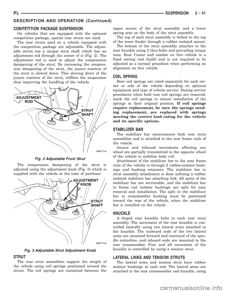
able struts use a unique strut shaft which has an
adjustment rod through the center of it (Fig. 2). The
adjustment rod is used to adjust the compression
dampening of the strut. By increasing the compres-
sion dampening of the strut, the jounce reaction of
the strut is slowed down. This slowing down of the
jounce reaction of the strut, stiffens the suspension
thus improving the handling of the vehicle.
The compression dampening of the strut is
adjusted using the adjustment knob (Fig. 3) which is
supplied with the vehicle at the time of purchase.
STRUT
The rear strut assemblies support the weight of
the vehicle using coil springs positioned around the
struts. The coil springs are contained between theupper mount of the strut assembly and a lower
spring seat on the body of the strut assembly.
The top of each strut assembly is bolted to the top
of the inner fender through a rubber isolated mount.
The bottom of the strut assembly attaches to the
rear knuckle using 2 thru-bolts and prevailing torque
nuts. Rear Caster and camber on this vehicle is a
fixed setting (net build) and is not required to be
adjusted as a normal procedure when performing an
alignment on this vehicle.
COIL SPRING
Rear coil springs are rated separately for each cor-
ner or side of the vehicle depending on optional
equipment and type of vehicle service. During service
procedures when both rear coil springs are removed,
mark the coil springs to ensure installation of the
springs in their original position.If coil springs
require replacement, be sure the springs need-
ing replacement, are replaced with springs
meeting the correct load rating for the vehicle
and its specific options.
STABILIZER BAR
The stabilizer bar interconnects both rear strut
assemblies and is attached to the rear frame rails of
the vehicle.
Jounce and rebound movements affecting one
wheel are partially transmitted to the opposite wheel
of the vehicle to stabilize body roll.
Attachment of the stabilizer bar to the rear frame
rails of the vehicle is through 2 rubber-isolator bush-
ings and bushing retainers. The stabilizer bar to
strut assembly attachment is done utilizing a rubber
isolated stabilizer bar attaching link. All parts of the
stabilizer bar are serviceable, and the stabilizer bar
to frame rail isolator bushings are split for easy
removal and installation. The split in the stabilizer
bar to crossmember bushing must be positioned
toward the rear of the vehicle, when the stabilizer
bar is installed on the vehicle.
KNUCKLE
A forged rear knuckle bolts to each rear strut
assembly. The movement of the rear knuckle is con-
trolled laterally using two lateral arms attached to
the knuckle. The outboard ends of the two lateral
arms are mounted forward and rearward of the spin-
dle centerline, and inboard ends are mounted to the
rear crossmember. Fore and aft movement of the
knuckle is controlled by using a tension strut.
LATERAL LINKS AND TENSION STRUTS
The lateral arms and tension strut have rubber
isolator bushings at each end. The lateral arms are
attached to the rear crossmember and knuckle, using
Fig. 2 Adjustable Front Strut
Fig. 3 Adjustable Strut Adjustment Knob
PLSUSPENSION 2 - 41
DESCRIPTION AND OPERATION (Continued)
Page 95 of 1200
DRUM BRAKE AUTOMATIC ADJUSTER
Place the vehicle on a hoist with a helper in the
driver's seat to apply the brakes. Remove the access
plug from the rear adjustment slot in each brake
support plate to provide access to the adjuster star
wheel. Then, to eliminate the possibility of maximum
adjustment, back the star wheel off approximately 10
notches. It will be necessary to hold the adjuster
lever away from the star wheel to permit this adjust-
ment.
Apply the brake pedal. This application of force
will cause the brake shoes to leave the anchor. Upon
application of the brake pedal, the lever should move
downward, turning the star wheel. Thus, a definite
rotation of the adjuster star wheel can be observed if
the automatic adjuster is working properly. If one or
more adjusters do not function properly, the respec-
tive drum must be removed for adjuster servicing.
ROTOR THICKNESS AND RUNOUT
Any servicing of the rotor requires extreme care to
maintain the rotor within service tolerances to
ensure proper brake action.
Before refinishing or refacing a rotor, the disc
should be checked and inspected for the following
conditions:
Braking surface scoring, rust, impregnation of lin-
ing material and worn ridges.
Excessive lateral runout or wobble.
Thickness variation (Parallelism).
Dishing or distortion (Flatness).
If a vehicle has not been driven for a period of
time, the rotor surface will rust in the area not cov-
ered by the brake lining and cause noise and chatter
when the brakes are applied.
Excessive wear and scoring of the rotor can cause
temporary improper lining contact if ridges are not
removed before installation of new brake pad assem-
blies.
Some discoloration or wear of the rotor surface is
normal and does not require resurfacing when lin-
ings are replaced.
Excessive runout or wobble in a rotor can increase
pedal travel due to piston knock back. This will
increase guide pin sleeve wear due to tendency of cal-
iper to follow rotor wobble.
Thickness variation in a rotor can also result in
pedal pulsation, chatter and surge due to variation in
brake output. This can also be caused by excessive
runout in rotor or hub.
Dishing or distortion can be caused by extreme
heat and abuse of the brakes.
ROTOR RUNOUT AND THICKNESS VARIATION
On vehicle rotor runout is the combination of the
individual runout of the hub face and the runout ofthe rotor. (The hub and rotor runouts are separable).
To measure runout on the vehicle, remove the wheel
and reinstall the lug nuts tightening the rotor to the
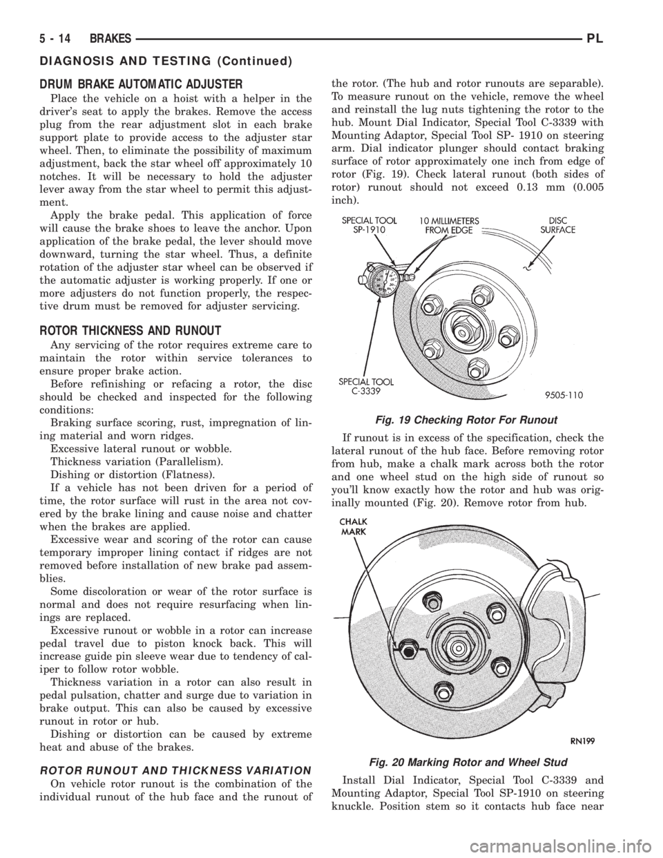
hub. Mount Dial Indicator, Special Tool C-3339 with
Mounting Adaptor, Special Tool SP- 1910 on steering
arm. Dial indicator plunger should contact braking
surface of rotor approximately one inch from edge of
rotor (Fig. 19). Check lateral runout (both sides of
rotor) runout should not exceed 0.13 mm (0.005
inch).
If runout is in excess of the specification, check the
lateral runout of the hub face. Before removing rotor
from hub, make a chalk mark across both the rotor
and one wheel stud on the high side of runout so
you'll know exactly how the rotor and hub was orig-
inally mounted (Fig. 20). Remove rotor from hub.
Install Dial Indicator, Special Tool C-3339 and
Mounting Adaptor, Special Tool SP-1910 on steering
knuckle. Position stem so it contacts hub face near
Fig. 19 Checking Rotor For Runout
Fig. 20 Marking Rotor and Wheel Stud
5 - 14 BRAKESPL
DIAGNOSIS AND TESTING (Continued)
Page 98 of 1200
(2) Remove hydraulic brake tube (Fig. 26) from
proportioning valve controlling the rear wheel of the
vehicle which has premature wheel skid.
(3) Remove proportioning valve from that outlet
port of the master cylinder.
CAUTION: Be sure the pressure test fitting being
installed into master cylinder, has the correct
thread sizes for installation into the master cylinder
and the installation of the proportioning valve.
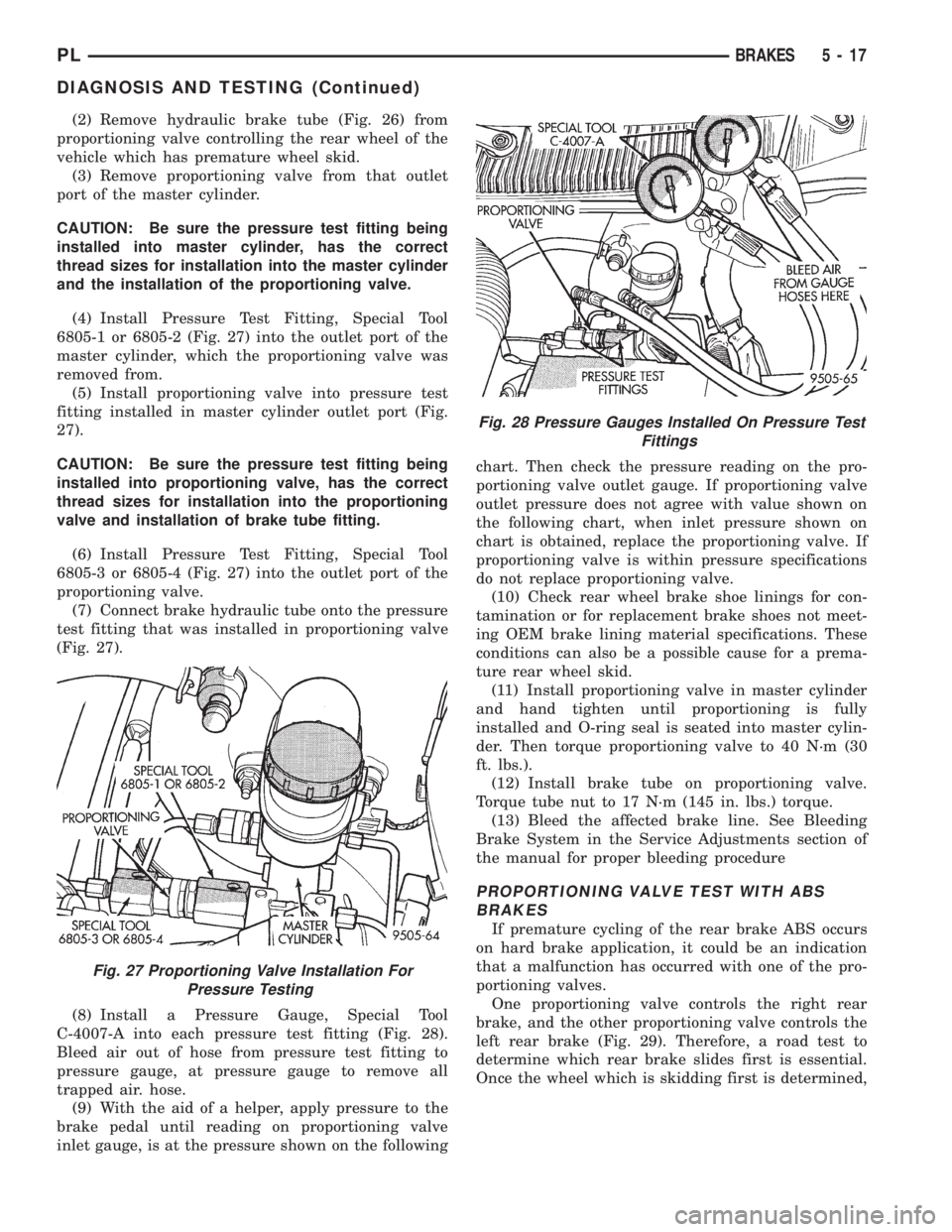
(4) Install Pressure Test Fitting, Special Tool
6805-1 or 6805-2 (Fig. 27) into the outlet port of the
master cylinder, which the proportioning valve was
removed from.
(5) Install proportioning valve into pressure test
fitting installed in master cylinder outlet port (Fig.
27).
CAUTION: Be sure the pressure test fitting being
installed into proportioning valve, has the correct
thread sizes for installation into the proportioning
valve and installation of brake tube fitting.
(6) Install Pressure Test Fitting, Special Tool
6805-3 or 6805-4 (Fig. 27) into the outlet port of the
proportioning valve.
(7) Connect brake hydraulic tube onto the pressure
test fitting that was installed in proportioning valve
(Fig. 27).
(8) Install a Pressure Gauge, Special Tool
C-4007-A into each pressure test fitting (Fig. 28).
Bleed air out of hose from pressure test fitting to
pressure gauge, at pressure gauge to remove all
trapped air. hose.
(9) With the aid of a helper, apply pressure to the
brake pedal until reading on proportioning valve
inlet gauge, is at the pressure shown on the followingchart. Then check the pressure reading on the pro-
portioning valve outlet gauge. If proportioning valve
outlet pressure does not agree with value shown on
the following chart, when inlet pressure shown on
chart is obtained, replace the proportioning valve. If
proportioning valve is within pressure specifications
do not replace proportioning valve.
(10) Check rear wheel brake shoe linings for con-
tamination or for replacement brake shoes not meet-
ing OEM brake lining material specifications. These
conditions can also be a possible cause for a prema-
ture rear wheel skid.
(11) Install proportioning valve in master cylinder
and hand tighten until proportioning is fully
installed and O-ring seal is seated into master cylin-
der. Then torque proportioning valve to 40 N´m (30
ft. lbs.).
(12) Install brake tube on proportioning valve.
Torque tube nut to 17 N´m (145 in. lbs.) torque.
(13) Bleed the affected brake line. See Bleeding
Brake System in the Service Adjustments section of
the manual for proper bleeding procedure
PROPORTIONING VALVE TEST WITH ABS
BRAKES
If premature cycling of the rear brake ABS occurs
on hard brake application, it could be an indication
that a malfunction has occurred with one of the pro-
portioning valves.
One proportioning valve controls the right rear
brake, and the other proportioning valve controls the
left rear brake (Fig. 29). Therefore, a road test to
determine which rear brake slides first is essential.
Once the wheel which is skidding first is determined,
Fig. 27 Proportioning Valve Installation For
Pressure Testing
Fig. 28 Pressure Gauges Installed On Pressure Test
Fittings
PLBRAKES 5 - 17
DIAGNOSIS AND TESTING (Continued)
Page 115 of 1200
or fluid leak is visible, disassemble caliper and
install a new seal and boot, (and piston if scored).
Refer to Caliper Disassembly And Re-Assembly Pro-
cedures in Disc Brake Caliper Service in this section
of the service manual.
Check the caliper dust boot and caliper pin bush-
ings to determine if they are in good condition.
Replace if they are damaged, dry, or found to be brit-
tle. Refer to Guide Pin Bushing Service in Disc
Brake Caliper Service in this section of the service
manual.
INSTALL
(1) Completely retract the caliper piston back into
the piston bore of the caliper assembly. This is
required for caliper installation when new brake pad
assemblies are installed on caliper.
(2) Lubricate both adapter abutments with a lib-
eral amount of MopartMultipurpose Lubricant, or
equivalent.
(3) Install rear rotor on the hub making sure it is
squarely seated on face of hub (Fig. 77).
(4) Remove protective paper from noise suppres-
sion gasket on both inner and outer brake pad
assemblies (if equipped).
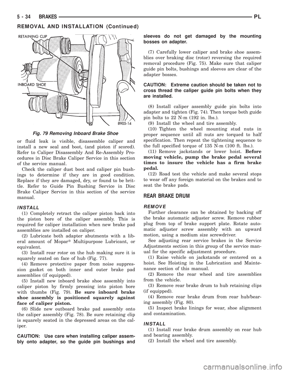
(5) Install new inboard brake shoe assembly into
caliper piston by firmly pressing into piston bore
with thumbs (Fig. 79).Be sure inboard brake
shoe assembly is positioned squarely against
face of caliper piston.
(6) Slide new outboard brake pad assembly onto
the caliper assembly (Fig. 78). Be sure retaining clip
is squarely seated in the depressed areas on the cal-
iper.
CAUTION: Use care when installing caliper assem-
bly onto adapter, so the guide pin bushings andsleeves do not get damaged by the mounting
bosses on adapter.
(7) Carefully lower caliper and brake shoe assem-
blies over braking disc (rotor) reversing the required
removal procedure (Fig. 75). Make sure that caliper
guide pin bolts, bushings and sleeves are clear of the
adapter bosses.
CAUTION: Extreme caution should be taken not to
cross thread the caliper guide pin bolts when they
are installed.
(8) Install caliper assembly guide pin bolts into
adapter and tighten (Fig. 74). Then torque both guide
pin bolts to 22 N´m (192 in. lbs.).
(9) Install the wheel and tire assembly.
(10) Tighten the wheel mounting stud nuts in
proper sequence until all nuts are torqued to half
specification. Then repeat the tightening sequence to
the full specified torque of 135 N´m (100 ft. lbs.).
(11) Remove jackstands or lower hoist.Before
moving vehicle, pump the brake pedal several
times to insure the vehicle has a firm brake
pedal.
(12) Road test the vehicle and make several stops
to wear off any foreign material on the brakes and to
seat the brake pads.
REAR BRAKE DRUM
REMOVE
Further clearance can be obtained by backing off
the brake automatic adjuster screw. Remove rubber
plug from top of brake support plate. Rotate auto-
matic adjuster screw assembly with an upward
motion, using a medium size screwdriver.
See adjusting rear service brakes in the Service
Adjustments section in this group of the service man-
ual for the specific adjustment procedure.
(1) Raise vehicle on jackstands or centered on a
hoist. See Hoisting in the Lubrication and Mainte-
nance section of this manual.
(2) Remove the rear wheel and tire assemblies
from the vehicle.
(3) Remove rear brake drum to hub retaining clips
(if equipped).
(4) Remove rear brake drum from rear hub/bear-
ing assembly (Fig. 80).
(5) Inspect brake linings for wear, shoe alignment
and contamination.
INSTALL
(1) Install rear brake drum assembly on rear hub
and bearing assembly.
(2) Install the wheel and tire assembly.
Fig. 79 Removing Inboard Brake Shoe
5 - 34 BRAKESPL
REMOVAL AND INSTALLATION (Continued)
Page 181 of 1200
INSTALLATION
(1) The pivot ball pocket in the fork is Teflon
coated and should be installed WITHOUT any lubri-
cant such as grease. Using grease will break down
the Teflon coating. Be sure the ball stud and fork
pocket are clean of contamination and dirt.
(2) Assemble the fork to the bearing. The small
pegs on the bearing must go over the fork arms.
(3) Slide the bearing and fork assembly onto the
input shaft bearing retainer, as a unit.
(4) Snap the clutch fork onto the pivot ball.
(5) Reinstall transaxle assembly. Refer to Group
21, Transaxle for further information.
CLEANING AND INSPECTION
CLUTCH CONTAMINATION
Fluid contamination is a frequent cause of clutch
malfunctions. Oil, grease, water, or other fluids on
the clutch contact surfaces will cause faulty opera-
tion.
During inspection, note if any components are con-
taminated. Look for evidence of oil, grease, or water/
road splash on clutch components.
OIL CONTAMINATION
Oil contamination indicates a leak at the rear main
seal and/or transaxle input shaft. Oil leaks produce a
residue of oil on the transaxle housing interior, clutch
cover and flywheel. Heat buildup caused by slippage
can bake the oil residue onto the components. This
glaze-like residue ranges in color from amber to
black.
GREASE CONTAMINATION
Grease contamination is usually a product of over-
lubrication. During clutch service, apply only a small
amount of grease to the input shaft splines. Excess
grease may be thrown off during operation, contami-
nating the disc.
ROAD SPLASH/WATER CONTAMINATION
Road splash contamination is usually caused by
driving the vehicle through deep water puddles.
Water can be forced into the clutch housing, causing
clutch components to become contaminated. Facing of
disc will absorb moisture and bond to the flywheel
and/or, pressure plate, if vehicle is allowed to stand
for some time before use. If this condition occurs,
replacement of clutch assembly may be required.
Drive the vehicle until normal clutch operating tem-
perature has been obtained. This will dry off disc
assembly, pressure plate, and flywheel.
CLEANING PRECAUTIONS
Condensation from steam vapors tend to accumu-
late on the internal clutch mechanism when the vehi-
cle is steam cleaned. Facing of disc will absorb
moisture and will bond to flywheel and/or pressure
plate, if vehicle is allowed to stand for some time
before use. If this condition occurs, it may require
replacement of clutch assembly. After cleaning, drive
the vehicle to its normal clutch operating tempera-
ture. This will dry off disc assembly, pressure plate,
and flywheel.
ADJUSTMENTS
CLUTCH CABLE
The manual transaxle clutch release system has a
unique self-adjusting mechanism to compensate for
clutch disc wear. This adjuster mechanism is located
within the clutch cable assembly. The preload spring
maintains tension on the cable. This tension keeps
the clutch release bearing continuously loaded
against the fingers of the clutch cover assembly.
ADJUSTER MECHANISM FUNCTION CHECK
(1) With slight pressure, pull the clutch release
lever end of the cable to draw the cable taut. Push
the clutch cable housing toward the dash panel. With
less than 25 lbs. of effort the cable housing should
move 30-50mm. This indicates proper adjuster mech-
anism function. If the cable does not adjust, deter-
mine if the mechanism is properly seated on the
bracket.
(2) If the adjust mechanism functions properly,
guide the cable through the slot in the transaxle
housing. Connect cable to release lever, seating the
cupped washer securely on lever tangs.
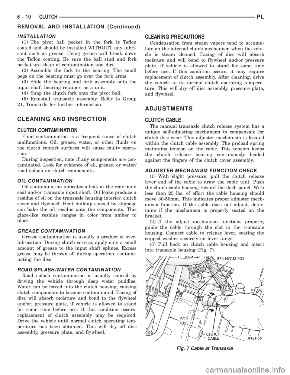
(3) Pull back on clutch cable housing and insert
into transaxle housing (Fig. 7).
Fig. 7 Cable at Transaxle
6 - 10 CLUTCHPL
REMOVAL AND INSTALLATION (Continued)
Page 306 of 1200
the plunger reaches the end of its travel. A ratchet-
ing sound will be heard during this procedure.
Connect the wiring harness to the switch. Mount
the switch into the bracket by holding the switch
with the plunger facing forward in car. There is an
index key on the switch that mates with the bracket
slot at the top of the square hole. Align key and push
switch into square hole in bracket while depressing
the brake pedal. Once the switch is seated in the
hole, rotate clockwise approximately 30 degrees to
lock into place. The switch will automatically adjust
when the pedal is released. Pull back on the pedal to
assure correct adjustment.
SPEED CONTROL SERVO CABLE
REMOVAL
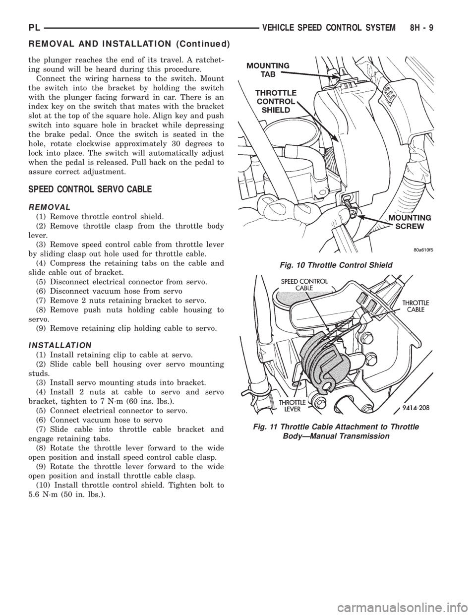
(1) Remove throttle control shield.
(2) Remove throttle clasp from the throttle body
lever.
(3) Remove speed control cable from throttle lever
by sliding clasp out hole used for throttle cable.
(4) Compress the retaining tabs on the cable and
slide cable out of bracket.
(5) Disconnect electrical connector from servo.
(6) Disconnect vacuum hose from servo
(7) Remove 2 nuts retaining bracket to servo.
(8) Remove push nuts holding cable housing to
servo.
(9) Remove retaining clip holding cable to servo.
INSTALLATION
(1) Install retaining clip to cable at servo.
(2) Slide cable bell housing over servo mounting
studs.
(3) Install servo mounting studs into bracket.
(4) Install 2 nuts at cable to servo and servo
bracket, tighten to 7 N´m (60 ins. lbs.).
(5) Connect electrical connector to servo.
(6) Connect vacuum hose to servo
(7) Slide cable into throttle cable bracket and
engage retaining tabs.
(8) Rotate the throttle lever forward to the wide
open position and install speed control cable clasp.
(9) Rotate the throttle lever forward to the wide
open position and install throttle cable clasp.
(10) Install throttle control shield. Tighten bolt to
5.6 N´m (50 in. lbs.).
Fig. 10 Throttle Control Shield
Fig. 11 Throttle Cable Attachment to Throttle
BodyÐManual Transmission
PLVEHICLE SPEED CONTROL SYSTEM 8H - 9
REMOVAL AND INSTALLATION (Continued)
Page 721 of 1200

cause of low compression unless some malfunc-
tion is present.
(11) Clean or replace spark plugs as necessary
and adjust gap as specified in Group 8, Electrical.
Tighten to specifications.
(12) Test resistance of spark plug cables. Refer to
Group 8, Electrical Ignition System Secondary Cir-
cuit Inspection.
(13) Test coil output voltage, primary and second-
ary resistance. Replace parts as necessary. Refer to
Group 8, Electrical Ignition System.
(14) Check fuel pump pressure at idle and differ-
ent RPM ranges. Refer to Group 14, Fuel System for
Specifications.
(15) The air filter elements should be replaced as
specified in Group 0, Lubrication and Maintenance,.
(16) Inspect crankcase ventilation system as out
lined in Group 0, Lubrication and Maintenance. For
emission controls see Group 25, Emission Controls
for service procedures.
(17) Inspect and adjust accessory belt drives refer-
ring to Group 7, Cooling System, Accessory Drive
Belts for proper adjustments.
(18) Road test vehicle as a final test.
CYLINDER COMBUSTION PRESSURE LEAKAGE
TEST
The combustion pressure leakage test provides an
accurate means for determining engine condition.
Combustion pressure leakage testing will detect:
²Exhaust and intake valve leaks (improper seat-
ing).
²Leaks between adjacent cylinders or into water
jacket.
²Any causes for combustion/compression pressure
loss.
WARNING: DO NOT REMOVE THE RADIATOR CAP
WITH THE SYSTEM HOT AND UNDER PRESSURE
BECAUSE SERIOUS BURNS FROM COOLANT CAN
OCCUR.
Check the coolant level and fill as required. DO
NOT install the radiator cap.
Start and operate the engine until it attains nor-
mal operating temperature, then turn the engine
OFF.
Clean spark plug recesses with compressed air.
Remove the spark plugs.
Remove the oil filler cap.
Remove the air cleaner.
Calibrate the tester according to the manufactur-
er's instructions. The shop air source for testing
should maintain 483 kPa (70 psi) minimum, 1 379
kPa (200 psi) maximum and 552 kPa (80 psi) recom-
mended.Perform the test procedures on each cylinder
according to the tester manufacturer's instructions.
While testing, listen for pressurized air escaping
through the throttle body, tailpipe and oil filler cap
opening. Check for bubbles in the radiator coolant.
All gauge pressure indications should be equal,
with no more than 25% leakage.
FOR EXAMPLE:At 552 kPa (80 psi) input pres-
sure, a minimum of 414 kPa (60 psi) should be main-
tained in the cylinder.
LASH ADJUSTER (TAPPET) NOISE DIAGNOSIS
A tappet-like noise may be produced from several
items. Check the following items.
(1) Engine oil level too high or too low. This may
cause aerated oil to enter the adjusters and cause
them to be spongy.
(2) Insufficient running time after rebuilding cylin-
der head. Low speed running up to 1 hour may be
required.
(3) During this time, turn engine off and let set for
a few minutes before restarting. Repeat this several
times after engine has reached normal operating
temperature.
(4) Low oil pressure.
(5) The oil restrictor pressed into the vertical oil
passage to the cylinder head is plugged with debris.
(6) Air ingested into oil due to broken or cracked
oil pump pick up.
(7) Worn valve guides.
(8) Rocker arm ears contacting valve spring
retainer.
(9) Rocker arm loose, adjuster stuck or at maxi-
mum extension and still leaves lash in the system.
(10) Faulty lash adjuster.
a. Check lash adjusters for sponginess while
installed in cylinder head. Depress part of rocker
arm over adjuster. Normal adjusters should feel very
firm. Spongy adjusters can be bottomed out easily.
b. Remove suspected rocker arms (sohc) or lash
adjuster (dohc) and replace.
INSPECTION (ENGINE OIL LEAKS IN GENERAL)
Begin with a through visual inspection of the
engine, particularly at the area of the suspected leak.
If an oil leak source is not readily identifiable, the
following steps should be followed:
(1) Do not clean or degrease the engine at this
time because some solvents may cause rubber to
swell, temporarily stopping the leak.
(2) Add an oil soluble dye (use as recommended by
manufacturer). Start the engine and let idle for
approximately 15 minutes. Check the oil dipstick to
make sure the dye is thoroughly mixed as indicated
with a bright yellow color under a black light.
9 - 8 ENGINEPL
DIAGNOSIS AND TESTING (Continued)