1999 DODGE NEON window
[x] Cancel search: windowPage 270 of 1200
INSTRUMENT PANEL AND SYSTEMS
CONTENTS
page page
GENERAL INFORMATION
INTRODUCTION......................... 1
DESCRIPTION AND OPERATION
DOME LAMP............................ 1
ELECTRONIC DIGITAL CLOCK.............. 1
INSTRUMENT CLUSTER................... 2
WARNING AND INDICATOR LAMPS......... 2
DIAGNOSIS AND TESTING
AIRBAG WARNING SYSTEM............... 2
BRAKE SYSTEM WARNING LAMP TEST...... 2
FOG LAMP SWITCH TEST................. 2
FUEL TANK SENDING UNIT TEST........... 3
HEADLAMP SWITCH TEST................. 3
HEATER A/C BLOWER SWITCH TEST........ 3
HEATER BLOWER SWITCH TEST............ 3
INDIVIDUAL GAUGE INOPERATIVE.......... 4
INSTRUMENT PANEL AND COMPONENTS.... 4
LOW OIL PRESSURE WARNING LAMP TEST . . 4
MULTIPLE GAUGE INOPERATIVE TEST....... 4
SEAT BELT REMINDER SYSTEM TEST....... 6
SENDING UNIT......................... 6
SERVICE ENGINE SOON INDICATOR......... 6
VEHICLE SPEED SENSOR TEST............. 6
REMOVAL AND INSTALLATION
ASH RECEIVER RETAINER AND LAMP....... 6
CENTER BEZEL.......................... 6
CIGAR LIGHTER RECEPTACLE.............. 6
CLUSTER LAMP......................... 7
CLUSTER PRINTED CIRCUIT BOARD........ 7CLUSTER.............................. 7
DOME LENS/LAMP....................... 8
FLOOR CONSOLE........................ 8
GAUGE................................ 8
GLOVE BOX DOOR/BIN................... 8
GLOVE BOX SWITCH/LAMP................ 9
HEADLAMP SWITCH..................... 9
HEATER A/C CONTROL BLOWER SWITCH . . . 10
HEATER A/C CONTROL LAMP............ 10
HEATER A/C CONTROL................... 9
HEATER CONTROL BLOWER SWITCH....... 10
IGNITION KEY LAMP.................... 10
INSTRUMENT PANEL.................... 10
LEFT TRIM PANEL...................... 10
ODOMETER............................ 10
RADIO................................ 12
REAR WINDOW DEFOGGER AND/OR FOG
LAMP SWITCH....................... 12
RIGHT TRIM PANEL..................... 12
SHIFTER KNOB......................... 13
STEERING COLUMN COVER LINER......... 13
STEERING COLUMN COVER.............. 13
STEERING COLUMN SHROUDS............ 13
TOP COVER AND CLUSTER BEZEL
REMOVAL........................... 14
TRANSMISSION RANGE INDICATOR LAMP . . 14
TRUNK LAMP/LENS..................... 14
VEHICLE SPEED SENSOR................ 14
GENERAL INFORMATION
INTRODUCTION
The purpose of the dash gauges and indicator
lamps is to keep the driver informed about the oper-
ating condition of the vehicle. If an abnormal condi-
tion occurs, the driver is informed by indicator lamp.
The driver can seek service before damage occurs.
Indicator lamps use ON/OFF switch functions for
operation, while gauges use a sending unit or sensor.
DESCRIPTION AND OPERATION
DOME LAMP
The Dome Lamp operates when a door is open or
when the headlamp switch is placed in courtesy posi-
tion.
ELECTRONIC DIGITAL CLOCK
The electronic digital clock is in the radio. The
clock and radio each use the display panel built into
the radio. A digital readout indicates the time in
hours and minutes whenever the ignition switch is in
the ON or ACC position.
PLINSTRUMENT PANEL AND SYSTEMS 8E - 1
Page 271 of 1200
When the ignition switch is in the OFF position, or
when the radio frequency is being displayed, time
keeping is accurately maintained.
The procedure for setting the clock varies slightly
with each radio. The correct procedure is described in
the individual radio operating instructions. Refer to
the Owner's Manual supplied with the vehicle.
INSTRUMENT CLUSTER
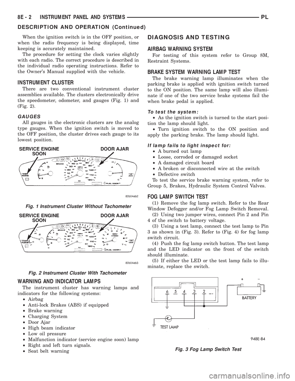
There are two conventional instrument cluster
assemblies available. The clusters electronically drive
the speedometer, odometer, and gauges (Fig. 1) and
(Fig. 2).
GAUGES
All gauges in the electronic clusters are the analog
type gauges. When the ignition switch is moved to
the OFF position, the cluster drives each gauge to its
lowest position.
WARNING AND INDICATOR LAMPS
The instrument cluster has warning lamps and
indicators for the following systems:
²Airbag
²Anti-lock Brakes (ABS) if equipped
²Brake warning
²Charging System
²Door Ajar
²High beam indicator
²Low oil pressure
²Malfunction indicator (service engine soon) lamp
²Right and left turn signals.
²Seat belt warning
DIAGNOSIS AND TESTING
AIRBAG WARNING SYSTEM
For testing of this system refer to Group 8M,
Restraint Systems.
BRAKE SYSTEM WARNING LAMP TEST
The brake warning lamp illuminates when the
parking brake is applied with ignition switch turned
to the ON position. The same lamp will also illumi-
nate if one of the two service brake systems fail the
when brake pedal is applied.
To test the system:
²As the ignition switch is turned to the start posi-
tion the lamp should light.
²Turn ignition switch to the ON position and
apply the parking brake. The lamp should light.
If lamp fails to light inspect for:
²A burned out lamp
²Loose, corroded or damaged socket
²A damaged circuit board
²A broken or disconnected wire at the switch
²Defective switch
To test the service brake warning system, refer to
Group 5, Brakes, Hydraulic System Control Valves.
FOG LAMP SWITCH TEST
(1) Remove the fog lamp switch. Refer to the Rear
Window Defogger and/or Fog Lamp Switch Removal.
(2) Using two jumper wires, connect Pin 2 and Pin
4 of the switch to battery voltage.
(3) Using a test lamp, connect the test lamp to Pin
3 as shown in (Fig. 3). Refer to (Fig. 4) for fog lamp
switch circuit.
(4) Push the fog lamp switch button. The test lamp
and the LED indicator on the front of the switch
should illuminate.
(5) If either the LED or the test lamp fails to illu-
minate, replace the switch.Fig. 1 Instrument Cluster Without Tachometer
Fig. 2 Instrument Cluster With Tachometer
Fig. 3 Fog Lamp Switch Test
8E - 2 INSTRUMENT PANEL AND SYSTEMSPL
DESCRIPTION AND OPERATION (Continued)
Page 278 of 1200
GLOVE BOX SWITCH/LAMP
REMOVAL
(1) Disconnect battery negative cable and isolate it
or remove fuse 12 prior to removing the switch, or
wires may short to ground.
(2) Open the glove box and push the glove box
sides inward allowing the door bumpers to clear and
the box to tip rearward.
(3) Reach inside the opening and squeeze the
lamp/switch retainers until they are disengage.
(4) Pull the switch/lamp rearward and remove it.
Replace the lamp. To replace the switch disconnect
wire and replace the switch.
INSTALLATION
For installation, reverse the above procedures.
HEADLAMP SWITCH
REMOVAL
(1) Remove the steering column cover and liner.
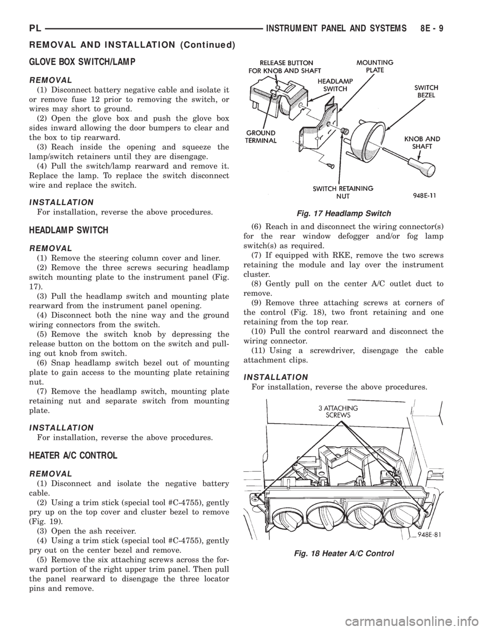
(2) Remove the three screws securing headlamp
switch mounting plate to the instrument panel (Fig.
17).
(3) Pull the headlamp switch and mounting plate
rearward from the instrument panel opening.
(4) Disconnect both the nine way and the ground
wiring connectors from the switch.
(5) Remove the switch knob by depressing the
release button on the bottom on the switch and pull-
ing out knob from switch.
(6) Snap headlamp switch bezel out of mounting
plate to gain access to the mounting plate retaining
nut.
(7) Remove the headlamp switch, mounting plate
retaining nut and separate switch from mounting
plate.
INSTALLATION
For installation, reverse the above procedures.
HEATER A/C CONTROL
REMOVAL
(1) Disconnect and isolate the negative battery
cable.
(2) Using a trim stick (special tool #C-4755), gently
pry up on the top cover and cluster bezel to remove
(Fig. 19).
(3) Open the ash receiver.
(4) Using a trim stick (special tool #C-4755), gently
pry out on the center bezel and remove.
(5) Remove the six attaching screws across the for-
ward portion of the right upper trim panel. Then pull
the panel rearward to disengage the three locator
pins and remove.(6) Reach in and disconnect the wiring connector(s)
for the rear window defogger and/or fog lamp
switch(s) as required.
(7) If equipped with RKE, remove the two screws
retaining the module and lay over the instrument
cluster.
(8) Gently pull on the center A/C outlet duct to
remove.
(9) Remove three attaching screws at corners of
the control (Fig. 18), two front retaining and one
retaining from the top rear.
(10) Pull the control rearward and disconnect the
wiring connector.
(11) Using a screwdriver, disengage the cable
attachment clips.
INSTALLATION
For installation, reverse the above procedures.
Fig. 17 Headlamp Switch
Fig. 18 Heater A/C Control
PLINSTRUMENT PANEL AND SYSTEMS 8E - 9
REMOVAL AND INSTALLATION (Continued)
Page 281 of 1200
(6) Remove the screws attaching lens, dial and
gauge assembly to the housing. The bottom screws
attaching lens to the housing can be accessed without
removing the foam pad.
(7) Remove the lens, dial and gauge assembly from
housing.
(8) Remove the two screws holding the odometer to
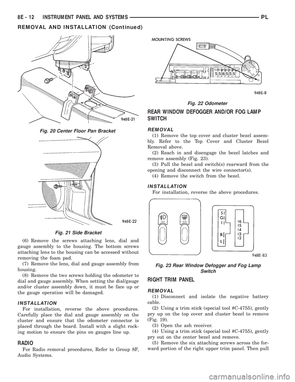
dial and gauge assembly. When setting the dial/gauge
and/or cluster assembly down, it must be face up or
the gauge operation will be damaged.
INSTALLATION
For installation, reverse the above procedures.
Carefully place the dial and gauge assembly on the
cluster and ensure that the odometer connector is
placed through the board. Install with a slight rock-
ing motion to ensure the pins on gauges line up.
RADIO
For Radio removal procedures, Refer to Group 8F,
Audio Systems.
REAR WINDOW DEFOGGER AND/OR FOG LAMP
SWITCH
REMOVAL
(1) Remove the top cover and cluster bezel assem-
bly. Refer to the Top Cover and Cluster Bezel
Removal above.
(2) Reach in and disengage the bezel latches and
remove assembly (Fig. 23).
(3) Pull the bezel and switch(s) rearward from the
opening and disconnect the wire connector(s).
(4) Remove the switch from the bezel.
INSTALLATION
For installation, reverse the above procedures.
RIGHT TRIM PANEL
REMOVAL
(1) Disconnect and isolate the negative battery
cable.
(2) Using a trim stick (special tool #C-4755), gently
pry up on the top cover and cluster bezel to remove
(Fig. 19).
(3) Open the ash receiver.
(4) Using a trim stick (special tool #C-4755), gently
pry out on the center bezel and remove.
(5) Remove the six attaching screws across the for-
ward portion of the right upper trim panel. Then pull
Fig. 20 Center Floor Pan Bracket
Fig. 21 Side Bracket
Fig. 22 Odometer
Fig. 23 Rear Window Defogger and Fog Lamp
Switch
8E - 12 INSTRUMENT PANEL AND SYSTEMSPL
REMOVAL AND INSTALLATION (Continued)
Page 282 of 1200
the panel rearward to disengage the three locator
pins and remove.
(6) Reach in and disconnect the wiring connector(s)
for the rear window defogger and/or fog lamp
switch(s) as required.
INSTALLATION
For installation, reverse the above procedures.
SHIFTER KNOB
AUTOMATIC TRANSMISSION SHIFTER
REMOVAL
(1) Loosen the set screw at the left side under the
button area.
(2) Pull up until the knob slides off the shifter
shaft.
INSTALLATION
For installation, reverse the above procedures.
MANUAL TRANSMISSION SHIFTER
REMOVAL
(1) Pull the top part of the boot down until the two
tabs at the bottom of the knob are exposed.
(2) Release the locking tabs from the pins on the
shifter shaft.
(3) Pull up until the knob slides off the shifter
shaft.INSTALLATION
For installation, reverse the above procedures.
STEERING COLUMN COVER
REMOVAL
(1) Remove the three attachment screws along the
bottom of the cover and screw on the left outward
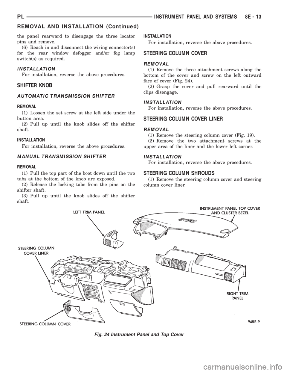
face of cover (Fig. 24).
(2) Grasp the cover and pull rearward until the
clips disengage.
INSTALLATION
For installation, reverse the above procedures.
STEERING COLUMN COVER LINER
REMOVAL
(1) Remove the steering column cover (Fig. 19).
(2) Remove the two attachment screws at the
upper area of the liner and the lower left corner.
INSTALLATION
For installation, reverse the above procedures.
STEERING COLUMN SHROUDS
(1) Remove the steering column cover and steering
column cover liner.
Fig. 24 Instrument Panel and Top Cover
PLINSTRUMENT PANEL AND SYSTEMS 8E - 13
REMOVAL AND INSTALLATION (Continued)
Page 284 of 1200
INSTRUMENT PANEL AND SYSTEMS
CONTENTS
page page
DIAGNOSIS AND TESTING
FOG LAMP SWITCH TEST................ 1
HEADLAMP LEVELING SWITCH........... 1
INSTRUMENT PANEL AND COMPONENTS . . . 2
REMOVAL AND INSTALLATION
END CAP RHD ......................... 2FRONT FOG LAMP SWITCH.............. 2
HEADLAMP LEVELING SWITCH........... 3
REAR WINDOW DEFOGGER AND/OR REAR
FOG LAMP SWITCH................... 3
DIAGNOSIS AND TESTING
FOG LAMP SWITCH TEST
Refer to Group 8W, Wiring Diagrams for wiring or
circuit information.
FRONT
(1) Remove the fog lamp switch and disconnect the
connector at the center stack.
(2) Using two jumper wires connect Pin L7 to bat-
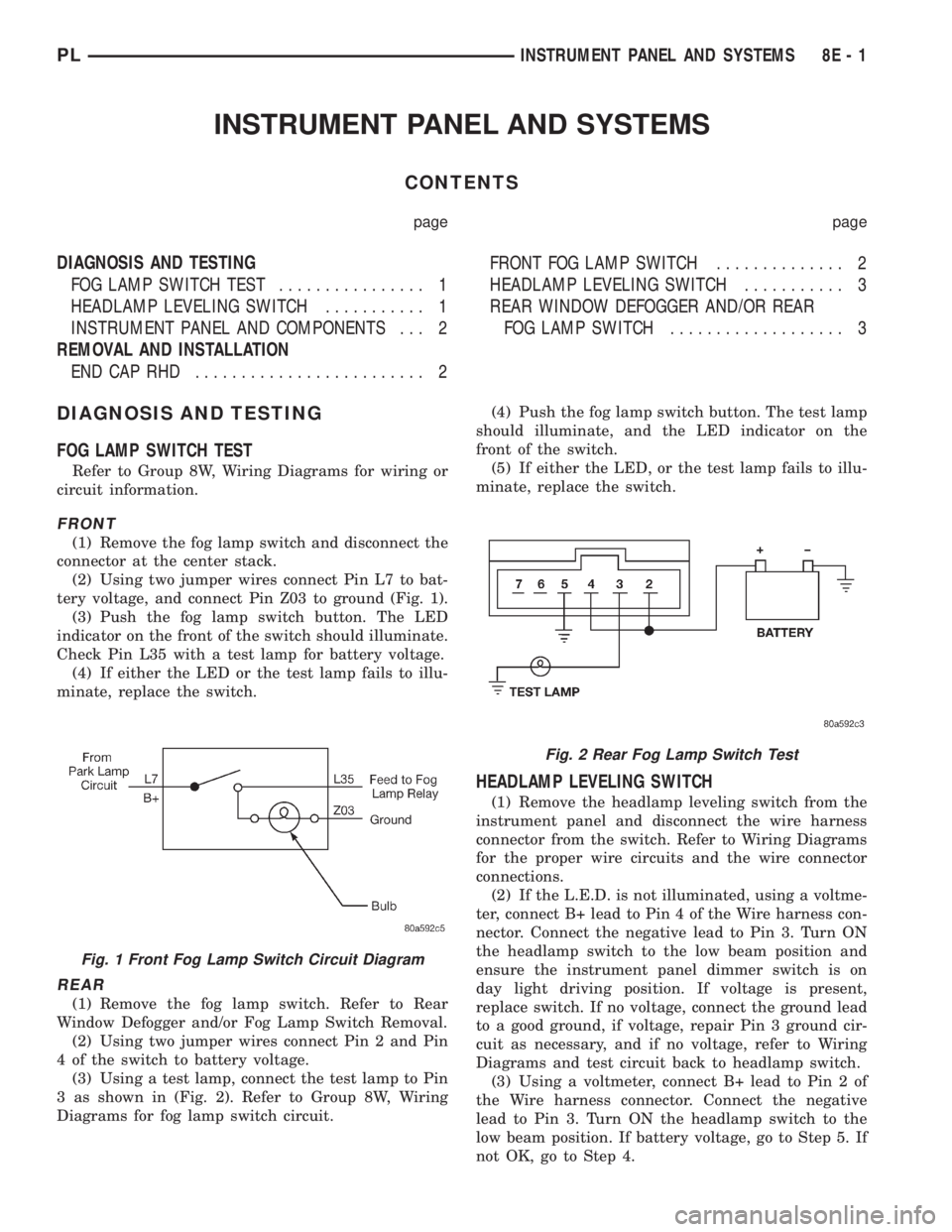
tery voltage, and connect Pin Z03 to ground (Fig. 1).
(3) Push the fog lamp switch button. The LED
indicator on the front of the switch should illuminate.
Check Pin L35 with a test lamp for battery voltage.
(4) If either the LED or the test lamp fails to illu-
minate, replace the switch.
REAR
(1) Remove the fog lamp switch. Refer to Rear
Window Defogger and/or Fog Lamp Switch Removal.
(2) Using two jumper wires connect Pin 2 and Pin
4 of the switch to battery voltage.
(3) Using a test lamp, connect the test lamp to Pin
3 as shown in (Fig. 2). Refer to Group 8W, Wiring
Diagrams for fog lamp switch circuit.(4) Push the fog lamp switch button. The test lamp
should illuminate, and the LED indicator on the
front of the switch.
(5) If either the LED, or the test lamp fails to illu-
minate, replace the switch.
HEADLAMP LEVELING SWITCH
(1) Remove the headlamp leveling switch from the
instrument panel and disconnect the wire harness
connector from the switch. Refer to Wiring Diagrams
for the proper wire circuits and the wire connector
connections.
(2) If the L.E.D. is not illuminated, using a voltme-
ter, connect B+ lead to Pin 4 of the Wire harness con-
nector. Connect the negative lead to Pin 3. Turn ON
the headlamp switch to the low beam position and
ensure the instrument panel dimmer switch is on
day light driving position. If voltage is present,
replace switch. If no voltage, connect the ground lead
to a good ground, if voltage, repair Pin 3 ground cir-
cuit as necessary, and if no voltage, refer to Wiring
Diagrams and test circuit back to headlamp switch.
(3) Using a voltmeter, connect B+ lead to Pin 2 of
the Wire harness connector. Connect the negative
lead to Pin 3. Turn ON the headlamp switch to the
low beam position. If battery voltage, go to Step 5. If
not OK, go to Step 4.
Fig. 1 Front Fog Lamp Switch Circuit Diagram
Fig. 2 Rear Fog Lamp Switch Test
PLINSTRUMENT PANEL AND SYSTEMS 8E - 1
Page 286 of 1200
HEADLAMP LEVELING SWITCH
REMOVAL
(1) Remove the top cover and cluster bezel assem-
bly.
(2) Disengage the headlamp leveling switch bezel
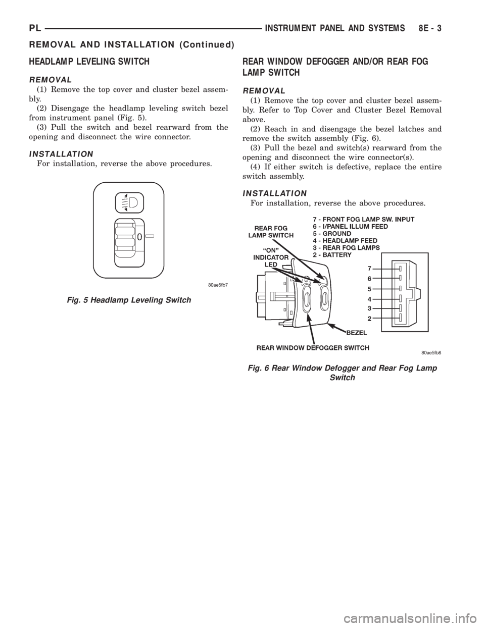
from instrument panel (Fig. 5).
(3) Pull the switch and bezel rearward from the
opening and disconnect the wire connector.
INSTALLATION
For installation, reverse the above procedures.
REAR WINDOW DEFOGGER AND/OR REAR FOG
LAMP SWITCH
REMOVAL
(1) Remove the top cover and cluster bezel assem-
bly. Refer to Top Cover and Cluster Bezel Removal
above.
(2) Reach in and disengage the bezel latches and
remove the switch assembly (Fig. 6).
(3) Pull the bezel and switch(s) rearward from the
opening and disconnect the wire connector(s).
(4) If either switch is defective, replace the entire
switch assembly.
INSTALLATION
For installation, reverse the above procedures.
Fig. 5 Headlamp Leveling Switch
Fig. 6 Rear Window Defogger and Rear Fog Lamp
Switch
PLINSTRUMENT PANEL AND SYSTEMS 8E - 3
REMOVAL AND INSTALLATION (Continued)
Page 317 of 1200
WIPER SYSTEM DIAGNOSIS
CONDITION POSSIBLE CAUSES CORRECTION
WIPER BLADES DO NOT
PARK PROPERLY1. WIPER ARMS
IMPROPERLY PARKED.
2. WIPER ARMS ARE
LOOSE ON PIVOT SHAFT.
3. MOTOR CRANK LOOSE
AT OUTPUT SHAFT.1. REMOVE WIPER ARMS AND REPARK.
REFER TO WIPER ARM REMOVAL AND
INSTALLATION.
2. REMOVE WIPER ARM AND REPARK.
REFER TO WIPER ARM REMOVAL AND
INSTALLATION.
3. REMOVE WIPER ARM, RUN WIPER
MOTOR TO PARK POSITION AND REMOVE
THE MODULE. WITHOUT ROTATING THE
MOTOR OUTPUT SHAFT, REMOVE THE
CRANK AND CLEAN ANY FOREIGN MATTER
FROM THE MOTOR SHAFT. INSTALL THE
MOTOR CRANK IN ITS ORIGINAL POSITION.
MOTOR STOPS IN ANY
POSITION WHEN THE
SWITCH IS TURNED OFF1. OPEN PARK CIRCUIT. 1. CHECK PARK SWITCH BY
DISCONNECTING THE WIRE CONNECTOR
AND APPLY BATTERY VOLTAGE TO PIN 4.
PLACE A JUMPER WIRE FROM PIN 2 TO
PIN 3 AND THEN TO AN EXTERNAL
GROUND. REPLACE MOTOR IF IT DOES
NOT PARK.
MOTOR WILL NOT STOP
WHEN THE SWITCH IS
TURNED OFF1. FAULTY SWITCH.
2. LOCK OF DYNAMIC
BRAKE ON WET GLASS.1. CHECK SWITCH IN LOW, HIGH AND
INTERMITTENT POSITION.
2. ENSURE PARK SWITCH HAS CLEAN
GROUND.
WIPER BLADES SLAP
AGAINST COWL SCREEN
OR WINDOW MOLDINGS.1. WIPER ARMS ARE
PARKED INCORRECTLY.1. PARK WIPER ARMS. REFER TO WIPER
ARM ADJUSTMENT.
BLADES CHATTER 1. FOREIGN SUBSTANCE
SUCH AS POLISH ON
GLASS OR BLADES.
2. ARMS TWISTED, BLADE
AT WRONG ANGLE ON
GLASS.
3. BLADE STRUCTURE
BENT.
4. BLADE ELEMENT HAS
PERMANENT SET.1. CLEAN GLASS AND BLADE ELEMENT
WITH NON-ABRASIVE CLEANER.
2. REPLACE ARM.
3. REPLACE BLADE.
4. REPLACE BLADE ELEMENT.
WIPER KNOCK AT
REVERSAL1. LINKAGE BUSHINGS
WORN.
2. ARMATURE ENDPLAY IN
MOTOR.1. REPLACE WORN LINK. REFER TO WIPER
LINKAGE REMOVAL AND INSTALLATION.
2. REPLACE WIPER MOTOR. REFER TO
WIPER MOTOR REMOVAL AND
INSTALLATION.
WIPER MOTOR WILL NOT
RUN1. BLOWN FUSE.
2. NEW FUSE BLOWS.
3. NEW FUSE BLOWS.
4. NO VOLTAGE AT MOTOR.
5. POOR GROUND.1. REPLACE FUSE, AND RUN SYSTEM.
2. CHECK FOR SHORT IN WIRING OR
SWITCH.
3. REPLACE FUSE, REMOVE MOTOR
CONNECTOR, TURN SWITCH ON, FUSE
DOES NOT BLOW, REPLACE MOTOR.
4. CHECK SWITCH AND WIRING HARNESS.
REFER TO GROUP 8W, WIRING DIAGRAMS.
5. REPAIR GROUND WIRE CONNECTION AS
NECESSARY.
8K - 4 WINDSHIELD WIPERS AND WASHERSPL
DIAGNOSIS AND TESTING (Continued)