1999 DODGE NEON turn signal bulb
[x] Cancel search: turn signal bulbPage 310 of 1200
TURN SIGNAL AND FLASHERS
CONTENTS
page page
GENERAL INFORMATION
INTRODUCTION......................... 1
DESCRIPTION AND OPERATION
COMBINATION FLASHER.................. 1
HAZARD WARNING SYSTEM............... 1DIAGNOSIS AND TESTING
MULTI-FUNCTION SWITCH................ 2
MULTI-FUNCTION SWITCH TEST............ 2
REMOVAL AND INSTALLATION
MULTI-FUNCTION SWITCH................ 4
GENERAL INFORMATION
INTRODUCTION
WARNING: ON VEHICLES EQUIPPED WITH AIR-
BAG, SEE GROUP 8M, RESTRAINT SYSTEMS FOR
AIRBAG REMOVAL PROCEDURES.
The turn signals are part of the multi-function
switch. Which contains:
²Electrical circuitry for turn signals
²Hazard warning switch
²Headlamp beam select switch
²Headlamp optical horn
The integrated switch assembly is mounted to the
left hand side of the steering column. When the
driver wishes to signal his intentions to change direc-
tion of travel, he moves the lever upward to cause
the right signals to flash and downward to cause the
left signals to flash. After completion of a turn the
system is deactivated automatically. As the steering
wheel returns to the straight ahead position, a can-
celing cam molded to the clockspring mechanism
comes in contact with the cancel actuator on the turn
signal multi-function switch assembly. The cam lobe,
pushing on the cancel actuator, returns the switch to
the off position.
If only momentary signaling such as indication of a
lane change is desired, the switch is actuated to a
left or right intermediate detent position. In this
position the signal lamps flash as described above,
but the switch returns to the OFF position as soon as
the lever is released.
When the system is activated, one of two indicator
lamps mounted in the instrument cluster flashes in
unison with the turn signal lamps, indicating to the
driver that the system is operating.
DESCRIPTION AND OPERATION
HAZARD WARNING SYSTEM
The hazard warning system is actuated by a slide
button located on the top of the steering column
between the steering wheel and the instrument
panel. The hazard switch is identified with a double
triangle on front of the button.
COMBINATION FLASHER
The turn signal flasher and the hazard warning
flasher are combined into one unit called a combina-
tion flasher (combo-flasher). The combo- flasher con-
trols the flashing of the hazard warning system and
the turn signal system. An inoperative bulb or incom-
plete turn signal circuit will cause the flasher rate to
double.
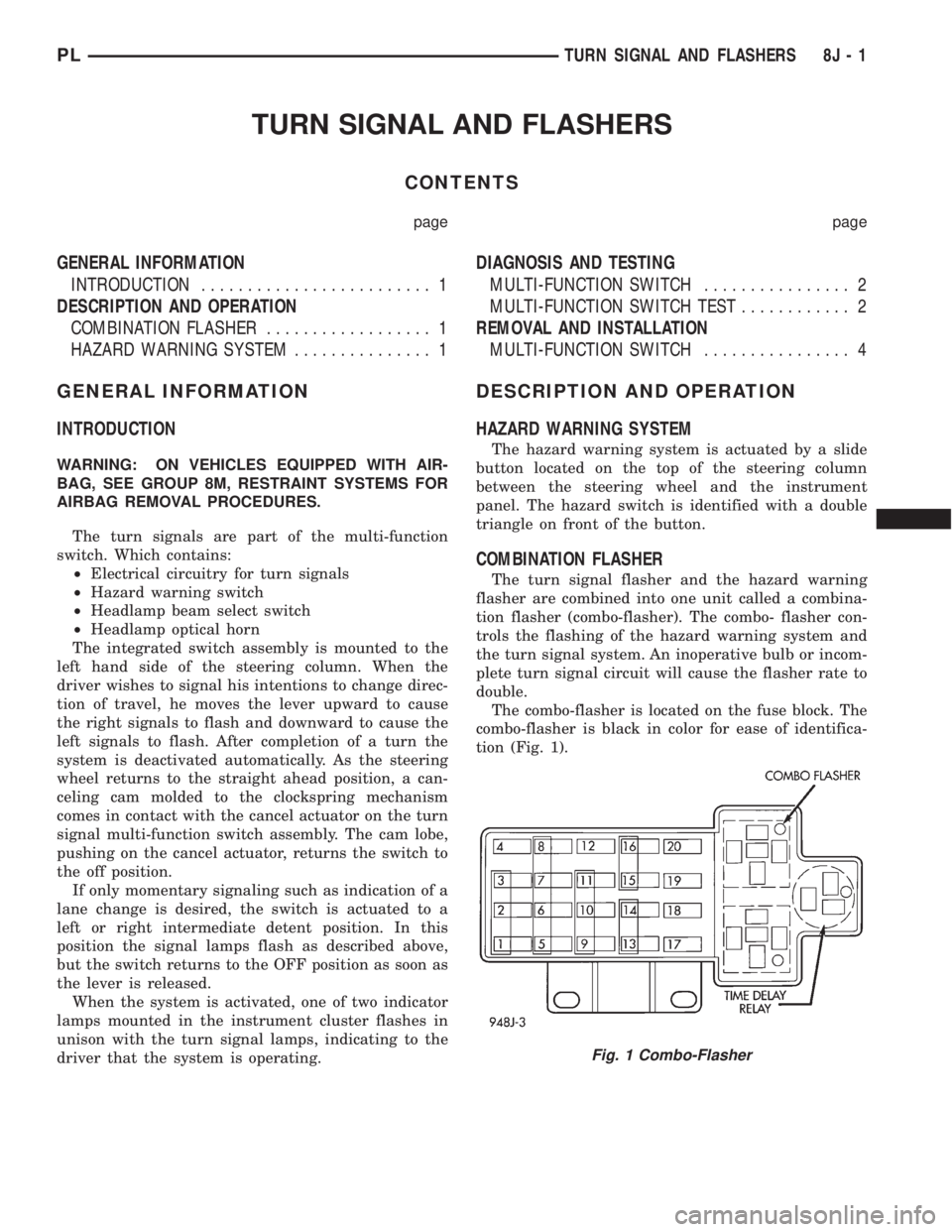
The combo-flasher is located on the fuse block. The
combo-flasher is black in color for ease of identifica-
tion (Fig. 1).
Fig. 1 Combo-Flasher
PLTURN SIGNAL AND FLASHERS 8J - 1
Page 335 of 1200
LAMP BULB SERVICE
INDEX
page page
REMOVAL AND INSTALLATION
CENTER HIGH MOUNTED STOP LAMP BULB . . . 7
DOME LAMP BULB....................... 8
FOG LAMP BULB......................... 6
FRONT SIDE MARKER LAMP BULB.......... 7
HEADLAMP BULB........................ 6
LICENSE PLATE LAMP BULB............... 8PARK AND TURN SIGNAL LAMP BULB........ 6
REAR CARGO LAMP BULB................. 8
TAIL, STOP, BACK-UP AND TURN SIGNAL
LAMP BULB........................... 7
UNDERHOOD LAMP BULB................. 8
VISOR VANITY LAMP BULB................. 8
REMOVAL AND INSTALLATION
HEADLAMP BULB
REMOVAL
(1) Release hood latch and open hood.
(2) Disengage wire connector from headlamp bulb
connector.
(3) Remove retaining ring holding bulb to back of
headlamp module.
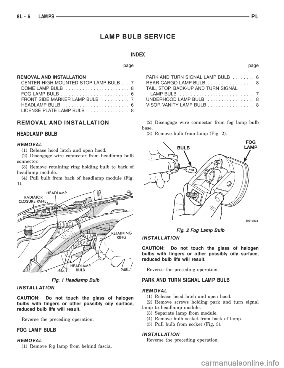
(4) Pull bulb from back of headlamp module (Fig.
1).
INSTALLATION
CAUTION: Do not touch the glass of halogen
bulbs with fingers or other possibly oily surface,
reduced bulb life will result.
Reverse the preceding operation.
FOG LAMP BULB
REMOVAL
(1) Remove fog lamp from behind fascia.(2) Disengage wire connector from fog lamp bulb
base.
(3) Remove bulb from lamp (Fig. 2).
INSTALLATION
CAUTION: Do not touch the glass of halogen
bulbs with fingers or other possibly oily surface,
reduced bulb life will result.
Reverse the preceding operation.
PARK AND TURN SIGNAL LAMP BULB
REMOVAL
(1) Release hood latch and open hood.
(2) Remove screws holding park and turn signal
lamp to headlamp module.
(3) Separate lamp from module.
(4) Remove bulb socket from back of lamp.
(5) Pull bulb from socket (Fig. 3).
INSTALLATION
Reverse the preceding operation.
Fig. 1 Headlamp Bulb
Fig. 2 Fog Lamp Bulb
8L - 6 LAMPSPL
Page 336 of 1200
FRONT SIDE MARKER LAMP BULB
REMOVAL
(1) Reach behind front bumper fascia forward of
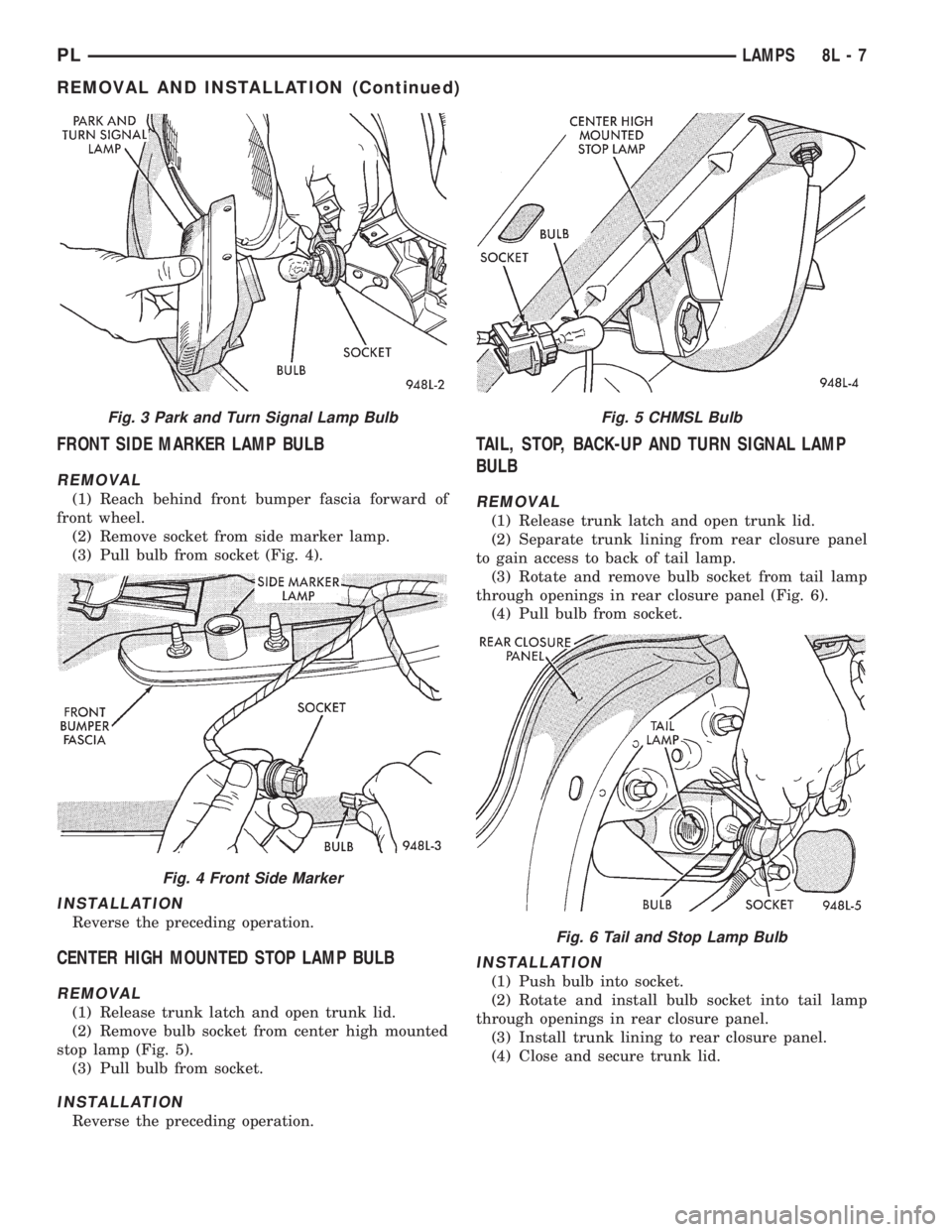
front wheel.
(2) Remove socket from side marker lamp.
(3) Pull bulb from socket (Fig. 4).
INSTALLATION
Reverse the preceding operation.
CENTER HIGH MOUNTED STOP LAMP BULB
REMOVAL
(1) Release trunk latch and open trunk lid.
(2) Remove bulb socket from center high mounted
stop lamp (Fig. 5).
(3) Pull bulb from socket.
INSTALLATION
Reverse the preceding operation.
TAIL, STOP, BACK-UP AND TURN SIGNAL LAMP
BULB
REMOVAL
(1) Release trunk latch and open trunk lid.
(2) Separate trunk lining from rear closure panel
to gain access to back of tail lamp.
(3) Rotate and remove bulb socket from tail lamp
through openings in rear closure panel (Fig. 6).
(4) Pull bulb from socket.
INSTALLATION
(1) Push bulb into socket.
(2) Rotate and install bulb socket into tail lamp
through openings in rear closure panel.
(3) Install trunk lining to rear closure panel.
(4) Close and secure trunk lid.
Fig. 3 Park and Turn Signal Lamp Bulb
Fig. 4 Front Side Marker
Fig. 5 CHMSL Bulb
Fig. 6 Tail and Stop Lamp Bulb
PLLAMPS 8L - 7
REMOVAL AND INSTALLATION (Continued)
Page 338 of 1200
LAMP SERVICE
INDEX
page page
REMOVAL AND INSTALLATION
CENTER HIGH MOUNTED STOP LAMP
(CHMSL)............................. 10
DOME LAMP........................... 11
FOG LAMP.............................. 9
FRONT SIDE MARKER LAMP.............. 10
HEADLAMP MODULE..................... 9LICENSE PLATE LAMP................... 11
PARK AND TURN SIGNAL LAMP............. 9
REAR CARGO LAMP..................... 11
TAIL, STOP AND TURN SIGNAL LAMP........ 10
UNDERHOOD LAMP..................... 11
VISOR VANITY LAMP..................... 11
REMOVAL AND INSTALLATION
HEADLAMP MODULE
REMOVAL
(1) Release hood latch and open hood.
(2) From behind bumper fascia, remove bolt hold-
ing outboard end of module to fender and closure
panel.
(3) Loosen bolts holding inboard end of module to
radiator closure panel and remove bolt to grille.
(4) Remove bolts attaching top of module to upper
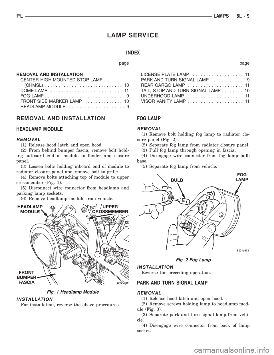
crossmember (Fig. 1).
(5) Disconnect wire connector from headlamp and
parking lamp sockets.
(6) Remove headlamp module from vehicle.
INSTALLATION
For installation, reverse the above procedures.
FOG LAMP
REMOVAL
(1) Remove bolt holding fog lamp to radiator clo-
sure panel (Fig. 2).
(2) Separate fog lamp from radiator closure panel.
(3) Pull fog lamp through opening in fascia.
(4) Disengage wire connector from fog lamp bulb
base.
(5) Separate fog lamp from vehicle.
INSTALLATION
Reverse the preceding operation.
PARK AND TURN SIGNAL LAMP
REMOVAL
(1) Release hood latch and open hood.
(2) Remove screws holding lamp to headlamp mod-
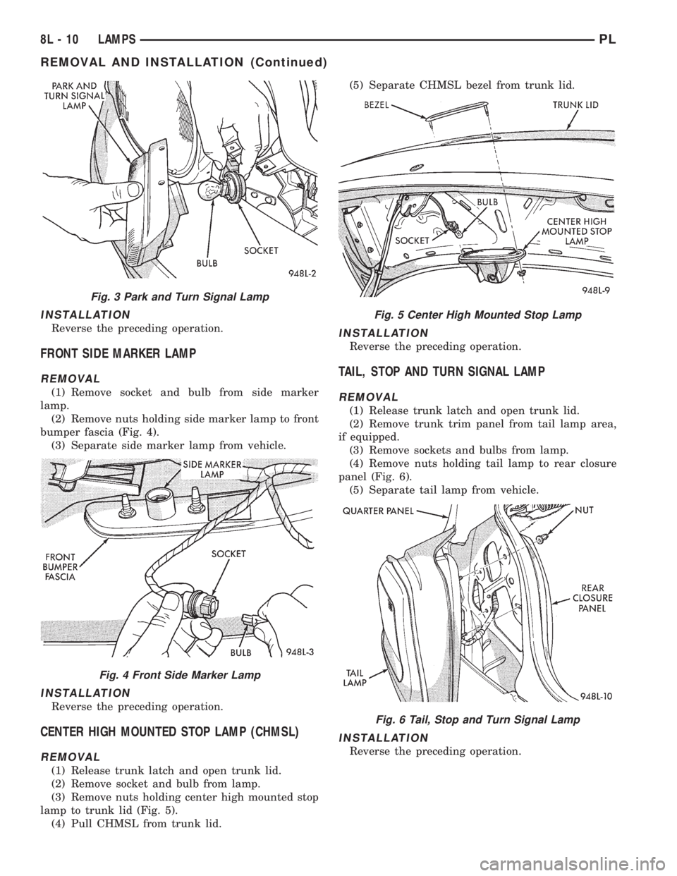
ule (Fig. 3).
(3) Separate park and turn signal lamp from vehi-
cle.
(4) Disengage wire connector from back of lamp
socket.
Fig. 1 Headlamp Module
Fig. 2 Fog Lamp
PLLAMPS 8L - 9
Page 339 of 1200
INSTALLATION
Reverse the preceding operation.
FRONT SIDE MARKER LAMP
REMOVAL
(1) Remove socket and bulb from side marker
lamp.
(2) Remove nuts holding side marker lamp to front
bumper fascia (Fig. 4).
(3) Separate side marker lamp from vehicle.
INSTALLATION
Reverse the preceding operation.
CENTER HIGH MOUNTED STOP LAMP (CHMSL)
REMOVAL
(1) Release trunk latch and open trunk lid.
(2) Remove socket and bulb from lamp.
(3) Remove nuts holding center high mounted stop
lamp to trunk lid (Fig. 5).
(4) Pull CHMSL from trunk lid.(5) Separate CHMSL bezel from trunk lid.
INSTALLATION
Reverse the preceding operation.
TAIL, STOP AND TURN SIGNAL LAMP
REMOVAL
(1) Release trunk latch and open trunk lid.
(2) Remove trunk trim panel from tail lamp area,
if equipped.
(3) Remove sockets and bulbs from lamp.
(4) Remove nuts holding tail lamp to rear closure
panel (Fig. 6).
(5) Separate tail lamp from vehicle.
INSTALLATION
Reverse the preceding operation.
Fig. 3 Park and Turn Signal Lamp
Fig. 4 Front Side Marker Lamp
Fig. 5 Center High Mounted Stop Lamp
Fig. 6 Tail, Stop and Turn Signal Lamp
8L - 10 LAMPSPL
REMOVAL AND INSTALLATION (Continued)
Page 342 of 1200
BULB APPLICATION
INDEX
page page
SPECIFICATIONS
EXTERIOR LAMPS....................... 13GENERAL INFORMATION................. 13
INTERIOR LAMPS....................... 13
SPECIFICATIONS
GENERAL INFORMATION
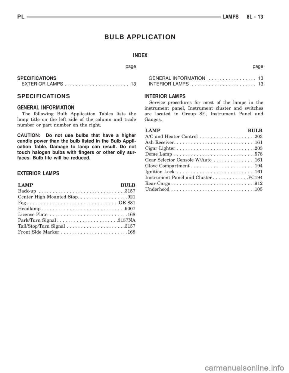
The following Bulb Application Tables lists the
lamp title on the left side of the column and trade
number or part number on the right.
CAUTION: Do not use bulbs that have a higher
candle power than the bulb listed in the Bulb Appli-
cation Table. Damage to lamp can result. Do not
touch halogen bulbs with fingers or other oily sur-
faces. Bulb life will be reduced.
EXTERIOR LAMPS
LAMP BULB
Back-up...............................3157
Center High Mounted Stop..................921
Fog.................................GE881
Headlamp..............................9007
License Plate............................168
Park/Turn Signal......................3157NA
Tail/Stop/Turn Signal.....................3157
Front Side Marker........................168
INTERIOR LAMPS
Service procedures for most of the lamps in the
instrument panel, Instrument cluster and switches
are located in Group 8E, Instrument Panel and
Gauges.
LAMP BULB
A/C and Heater Control....................203
Ash Receiver.............................161
Cigar Lighter............................203
Dome Lamp.............................578
Gear Selector Console W/Auto...............161
Glove Compartment.......................194
Ignition Lock............................161
Instrument Panel and Cluster.............PC194
Rear Cargo..............................912
Underhood..............................105
PLLAMPS 8L - 13
Page 345 of 1200
LAMP BULB SERVICE
INDEX
page page
REMOVAL AND INSTALLATION
CITYLIGHT LAMP BULB.................... 3
FOG LAMP BULB......................... 3FRONT TURN SIGNAL LAMP BULB........... 2
HEADLAMP BULB........................ 2
SIDE REPEATER LAMP BULB............... 4
REMOVAL AND INSTALLATION
HEADLAMP BULB
REMOVAL
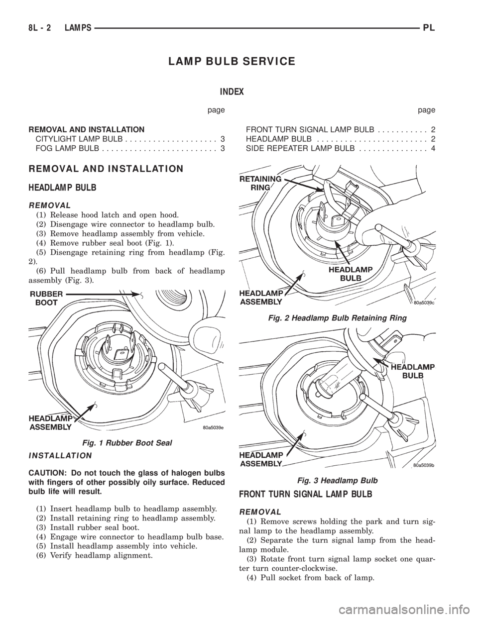
(1) Release hood latch and open hood.
(2) Disengage wire connector to headlamp bulb.
(3) Remove headlamp assembly from vehicle.
(4) Remove rubber seal boot (Fig. 1).
(5) Disengage retaining ring from headlamp (Fig.
2).
(6) Pull headlamp bulb from back of headlamp
assembly (Fig. 3).
INSTALLATION
CAUTION: Do not touch the glass of halogen bulbs
with fingers of other possibly oily surface. Reduced
bulb life will result.
(1) Insert headlamp bulb to headlamp assembly.
(2) Install retaining ring to headlamp assembly.
(3) Install rubber seal boot.
(4) Engage wire connector to headlamp bulb base.
(5) Install headlamp assembly into vehicle.
(6) Verify headlamp alignment.
FRONT TURN SIGNAL LAMP BULB
REMOVAL
(1) Remove screws holding the park and turn sig-
nal lamp to the headlamp assembly.
(2) Separate the turn signal lamp from the head-
lamp module.
(3) Rotate front turn signal lamp socket one quar-
ter turn counter-clockwise.
(4) Pull socket from back of lamp.
Fig. 1 Rubber Boot Seal
Fig. 2 Headlamp Bulb Retaining Ring
Fig. 3 Headlamp Bulb
8L - 2 LAMPSPL
Page 346 of 1200
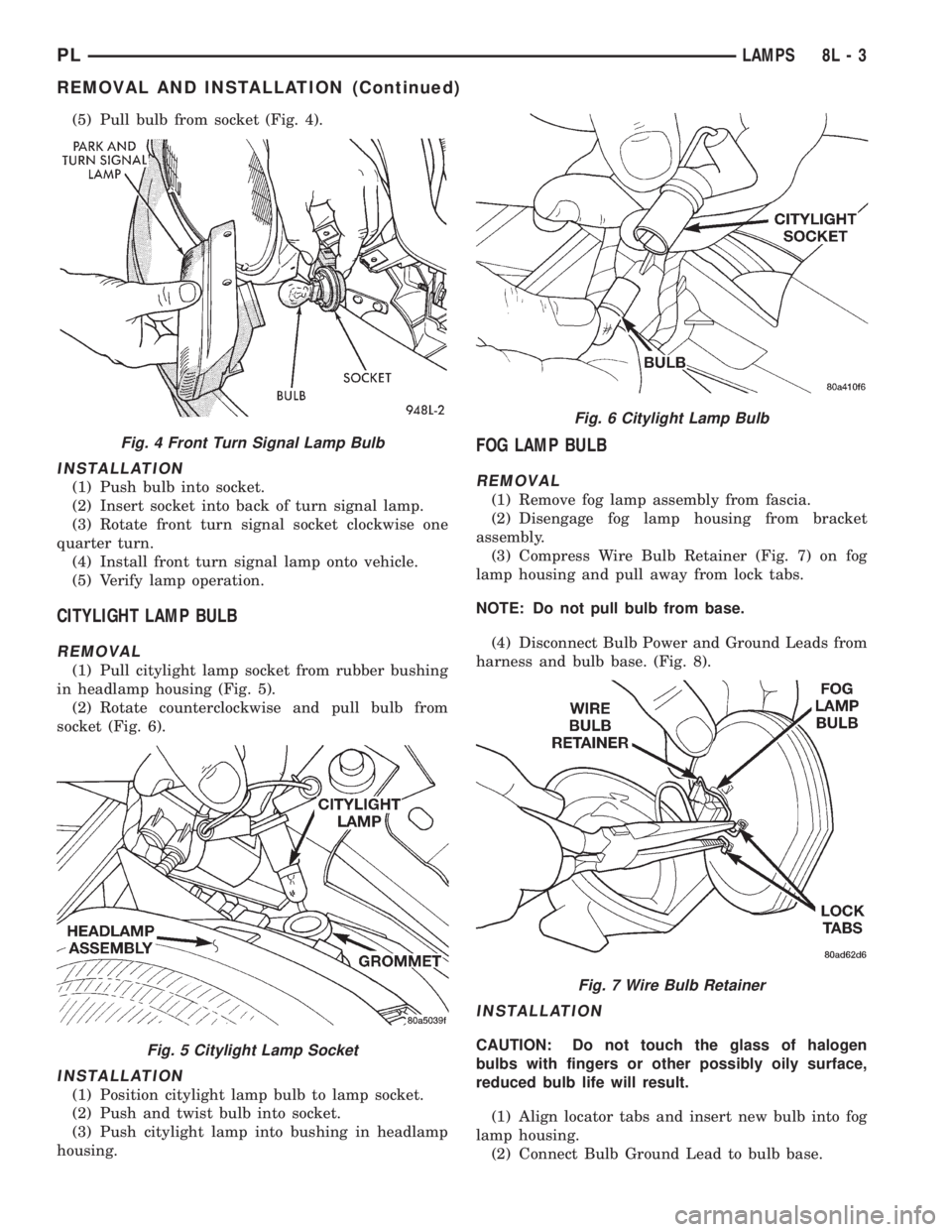
(5) Pull bulb from socket (Fig. 4).
INSTALLATION
(1) Push bulb into socket.
(2) Insert socket into back of turn signal lamp.
(3) Rotate front turn signal socket clockwise one
quarter turn.
(4) Install front turn signal lamp onto vehicle.
(5) Verify lamp operation.
CITYLIGHT LAMP BULB
REMOVAL
(1) Pull citylight lamp socket from rubber bushing
in headlamp housing (Fig. 5).
(2) Rotate counterclockwise and pull bulb from
socket (Fig. 6).
INSTALLATION
(1) Position citylight lamp bulb to lamp socket.
(2) Push and twist bulb into socket.
(3) Push citylight lamp into bushing in headlamp
housing.
FOG LAMP BULB
REMOVAL
(1) Remove fog lamp assembly from fascia.
(2) Disengage fog lamp housing from bracket
assembly.
(3) Compress Wire Bulb Retainer (Fig. 7) on fog
lamp housing and pull away from lock tabs.
NOTE: Do not pull bulb from base.
(4) Disconnect Bulb Power and Ground Leads from
harness and bulb base. (Fig. 8).
INSTALLATION
CAUTION: Do not touch the glass of halogen
bulbs with fingers or other possibly oily surface,
reduced bulb life will result.
(1) Align locator tabs and insert new bulb into fog
lamp housing.
(2) Connect Bulb Ground Lead to bulb base.
Fig. 4 Front Turn Signal Lamp Bulb
Fig. 5 Citylight Lamp Socket
Fig. 6 Citylight Lamp Bulb
Fig. 7 Wire Bulb Retainer
PLLAMPS 8L - 3
REMOVAL AND INSTALLATION (Continued)