1999 DODGE NEON traction control
[x] Cancel search: traction controlPage 152 of 1200

PREMATURE ABS CYCLING
NOTE: When working on a vehicle which has a
complaint of premature ABS cycling it may be nec-
essary to use a DRB Scan Tool to detect and verify
the condition.
There is one complaint called Premature ABS
Cycling in which neither the Red Brake Warning
Lamp nor the Amber Antilock Lamp were illumi-
nated and no fault codes were stored in the CAB.
Symptoms of Premature ABS Cycling, include click-
ing sounds from the solenoids valves, pump motor
running and pulsations in the brake pedal. This con-
dition can occur at any braking rate of the vehicle
and on any type of road surface. This creates an
additional condition which needs to be correctly
assessed when diagnosing problems with the antilock
brake system.
The following conditions are common causes that
need to be checked when diagnosing a condition of
Premature ABS Cycling. Damaged tone wheels,
incorrect tone wheels, damage to a wheel speed sen-
sor mounting boss on a steering knuckle, a loose
wheel speed sensor mounting bolt, and excessive tone
wheel runout. Also, an excessively large tone wheel
to wheel speed sensor air gap can lead to the condi-
tion of Premature ABS Cycling. Special attention is
to be given to these components when diagnosing a
vehicle exhibiting the condition of Premature ABS
Cycling. After diagnosing the defective component,
repair or replace as required.
When the component repair or replacement is com-
pleted, test drive the vehicle to verify the condition of
Premature ABS Cycling has been corrected.
ABS BRAKE SYSTEM COMPONENTS
The following is a detailed description of the Teves
Mark 20 ABS brake system components. For infor-
mation on servicing the base brake system compo-
nents, see the base Brake System section of this
Service Manual.
ABS MASTER CYLINDER AND POWER BRAKE
BOOSTER
A vehicle equipped with the Teves Mark 20 ABS
uses a different master cylinder and power brake
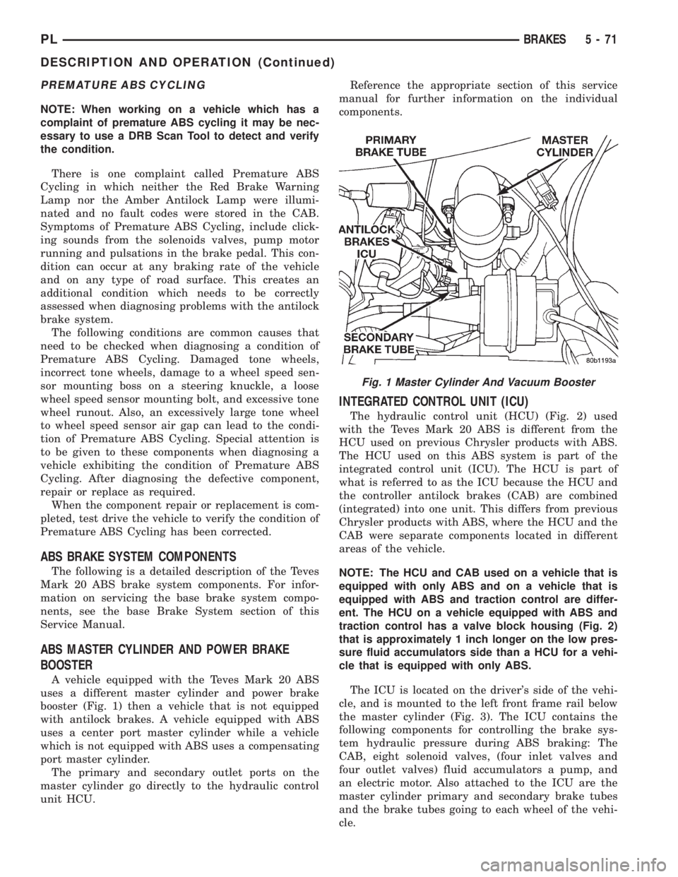
booster (Fig. 1) then a vehicle that is not equipped
with antilock brakes. A vehicle equipped with ABS
uses a center port master cylinder while a vehicle
which is not equipped with ABS uses a compensating
port master cylinder.
The primary and secondary outlet ports on the
master cylinder go directly to the hydraulic control
unit HCU.Reference the appropriate section of this service
manual for further information on the individual
components.
INTEGRATED CONTROL UNIT (ICU)
The hydraulic control unit (HCU) (Fig. 2) used
with the Teves Mark 20 ABS is different from the
HCU used on previous Chrysler products with ABS.
The HCU used on this ABS system is part of the
integrated control unit (ICU). The HCU is part of
what is referred to as the ICU because the HCU and
the controller antilock brakes (CAB) are combined
(integrated) into one unit. This differs from previous
Chrysler products with ABS, where the HCU and the
CAB were separate components located in different
areas of the vehicle.
NOTE: The HCU and CAB used on a vehicle that is
equipped with only ABS and on a vehicle that is
equipped with ABS and traction control are differ-
ent. The HCU on a vehicle equipped with ABS and
traction control has a valve block housing (Fig. 2)
that is approximately 1 inch longer on the low pres-
sure fluid accumulators side than a HCU for a vehi-
cle that is equipped with only ABS.
The ICU is located on the driver's side of the vehi-
cle, and is mounted to the left front frame rail below
the master cylinder (Fig. 3). The ICU contains the
following components for controlling the brake sys-
tem hydraulic pressure during ABS braking: The
CAB, eight solenoid valves, (four inlet valves and
four outlet valves) fluid accumulators a pump, and
an electric motor. Also attached to the ICU are the
master cylinder primary and secondary brake tubes
and the brake tubes going to each wheel of the vehi-
cle.
Fig. 1 Master Cylinder And Vacuum Booster
PLBRAKES 5 - 71
DESCRIPTION AND OPERATION (Continued)
Page 155 of 1200

integral part of the rear wheel hub and bearing
assembly. The speed sensor air gap on both applica-
tions is NOT adjustable.
The four Wheel Speed Sensors are serviced individ-
ually. The front Tone Wheels are serviced as an
assembly with the outboard constant velocity joint.
The rear Tone Wheels are serviced as an assembly
with the rear hub and bearing assembly.
Correct ABS system operation is dependent on
accurate wheel speed signals. The vehicle's wheels
and tires must all be the same size and type to gen-
erate accurate signals. Variations in wheel and tire
size can produce inaccurate wheel speed signals.
CONTROLLER ANTILOCK BRAKES (CAB)
The Controller Antilock Brakes (CAB) is a micro-
processor based device which monitors the ABS sys-
tem during normal braking and controls it when the
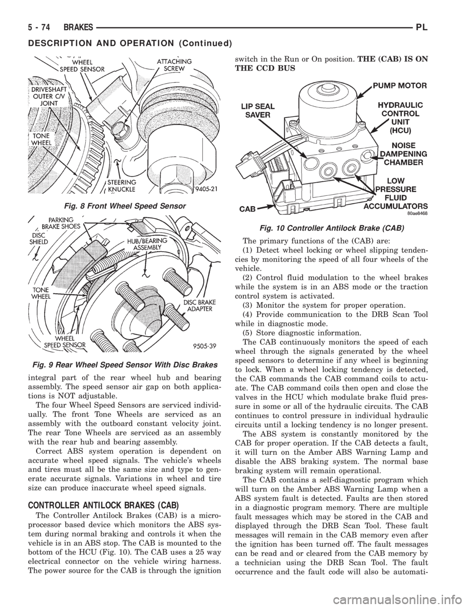
vehicle is in an ABS stop. The CAB is mounted to the
bottom of the HCU (Fig. 10). The CAB uses a 25 way
electrical connector on the vehicle wiring harness.
The power source for the CAB is through the ignitionswitch in the Run or On position.THE (CAB) IS ON
THE CCD BUS
The primary functions of the (CAB) are:
(1) Detect wheel locking or wheel slipping tenden-
cies by monitoring the speed of all four wheels of the
vehicle.
(2) Control fluid modulation to the wheel brakes
while the system is in an ABS mode or the traction
control system is activated.
(3) Monitor the system for proper operation.
(4) Provide communication to the DRB Scan Tool
while in diagnostic mode.
(5) Store diagnostic information.
The CAB continuously monitors the speed of each
wheel through the signals generated by the wheel
speed sensors to determine if any wheel is beginning
to lock. When a wheel locking tendency is detected,
the CAB commands the CAB command coils to actu-
ate. The CAB command coils then open and close the
valves in the HCU which modulate brake fluid pres-
sure in some or all of the hydraulic circuits. The CAB
continues to control pressure in individual hydraulic
circuits until a locking tendency is no longer present.
The ABS system is constantly monitored by the
CAB for proper operation. If the CAB detects a fault,
it will turn on the Amber ABS Warning Lamp and
disable the ABS braking system. The normal base
braking system will remain operational.
The CAB contains a self-diagnostic program which
will turn on the Amber ABS Warning Lamp when a
ABS system fault is detected. Faults are then stored
in a diagnostic program memory. There are multiple
fault messages which may be stored in the CAB and
displayed through the DRB Scan Tool. These fault
messages will remain in the CAB memory even after
the ignition has been turned off. The fault messages
can be read and or cleared from the CAB memory by
a technician using the DRB Scan Tool. The fault
occurrence and the fault code will also be automati-
Fig. 8 Front Wheel Speed Sensor
Fig. 9 Rear Wheel Speed Sensor With Disc Brakes
Fig. 10 Controller Antilock Brake (CAB)
5 - 74 BRAKESPL
DESCRIPTION AND OPERATION (Continued)
Page 1070 of 1200

weather temperature varies widely. Tire pressure will
decrease when the outdoor temperature drops.
Inflation pressures specified on the placard are
always the cold inflation pressure of the tire. Cold
inflation pressure is obtained after the vehicle has
not been operated for at least 3 hours, or the vehicle
is driven less than one mile after being inoperative
for 3 hours. Tire inflation pressures may increase
from 2 to 6 pounds per square inch (psi) during oper-
ation. Do not reduce this normal pressure build-up.
WARNING: OVER OR UNDER INFLATED TIRES
CAN AFFECT VEHICLE HANDLING. THE TIRE CAN
FAIL SUDDENLY, RESULTING IN LOSS OF VEHICLE
CONTROL.
TIRE PRESSURE FOR HIGH SPEED OPERATION
Chrysler Corporation advocates driving at safe
speeds within posted speed limits. Where speed lim-
its allow the vehicle to be driven at high speeds, cor-
rect tire inflation pressure is very important. For
speeds up to and including 120 km/h (75 mph), tires
must be inflated to the pressures shown on the tire
placard. For continuous speeds in excess of 120 km/h
(75 mph), tires must be inflated to the maximum
pressure specified on the tire sidewall.
Vehicles loaded to the maximum capacity should
not be driven at continuous speeds above 75 mph
(120 km/h).
For emergency vehicles that are driven at speeds
over 90 mph (144 km/h), special high speed tires
must be used. Consult tire manufacturer for correct
inflation pressure recommendations.
REPLACEMENT TIRES
The original equipment tires provide a proper bal-
ance of many characteristics such as:
²Ride
²Noise
²Handling
²Durability
²Tread life
²Traction
²Rolling resistance
²Speed capability
It is recommend that tires equivalent to the origi-
nal equipment tires be used when replacement is
needed.
Failure to use equivalent replacement tires may
adversely affect the safety and handling of the vehi-
cle.
The use of oversize tires not listed in the specifica-
tion charts may cause interference with vehicle com-
ponents. Under extremes of suspension and steering
travel, interference with vehicle components may
cause tire damage.WARNING: FAILURE TO EQUIP THE VEHICLE WITH
TIRES HAVING ADEQUATE SPEED CAPABILITY
CAN RESULT IN SUDDEN TIRE FAILURE.
DIAGNOSIS AND TESTING
PRESSURE GAUGES
A quality air pressure gauge is recommended to
check tire pressure. After checking the air pressure,
replace valve cap finger tight.
TREAD WEAR INDICATORS
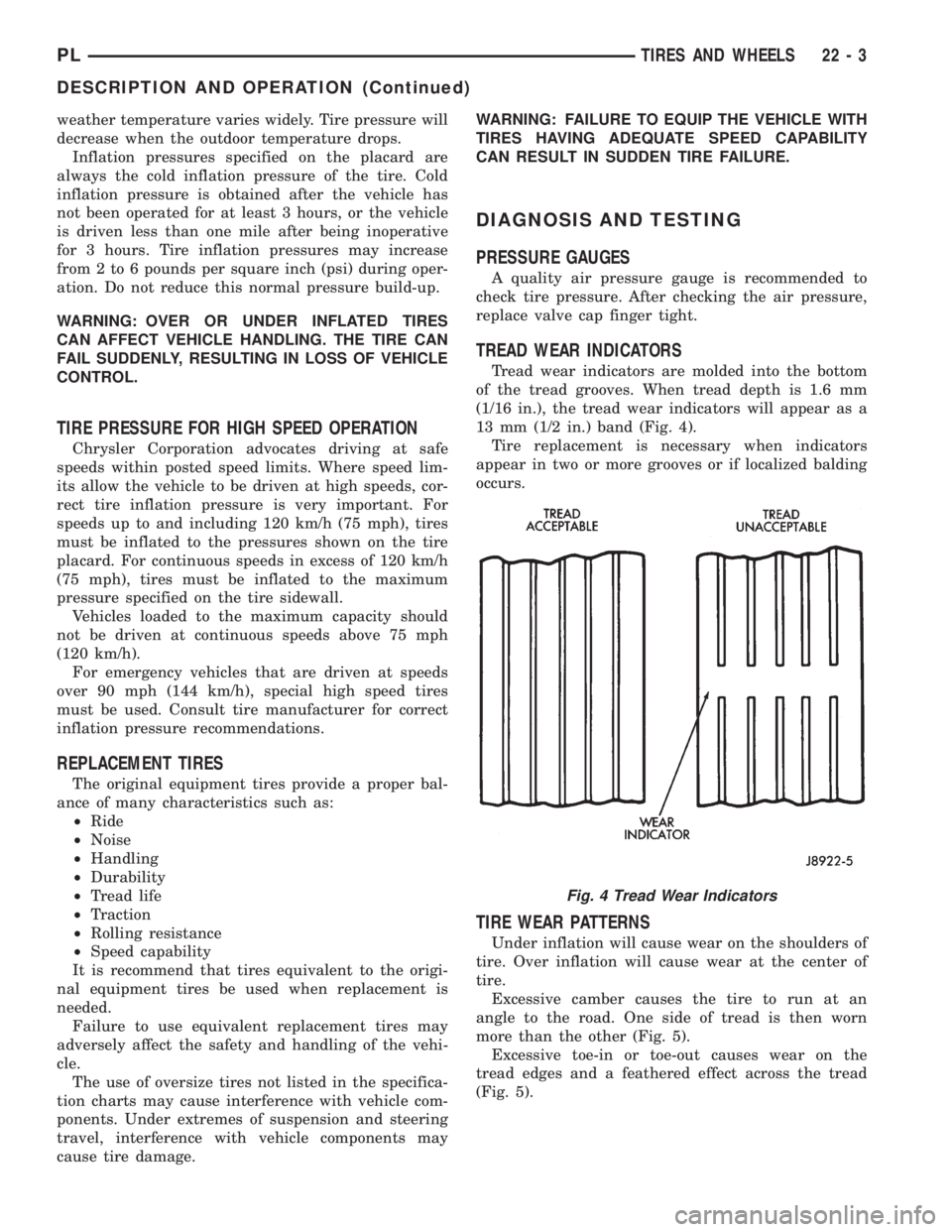
Tread wear indicators are molded into the bottom
of the tread grooves. When tread depth is 1.6 mm
(1/16 in.), the tread wear indicators will appear as a
13 mm (1/2 in.) band (Fig. 4).
Tire replacement is necessary when indicators
appear in two or more grooves or if localized balding
occurs.
TIRE WEAR PATTERNS
Under inflation will cause wear on the shoulders of
tire. Over inflation will cause wear at the center of
tire.
Excessive camber causes the tire to run at an
angle to the road. One side of tread is then worn
more than the other (Fig. 5).
Excessive toe-in or toe-out causes wear on the
tread edges and a feathered effect across the tread
(Fig. 5).
Fig. 4 Tread Wear Indicators
PLTIRES AND WHEELS 22 - 3
DESCRIPTION AND OPERATION (Continued)