1999 DODGE NEON belt
[x] Cancel search: beltPage 4 of 1200
MAINTENANCE SCHEDULES
INDEX
page page
GENERAL INFORMATION
INTRODUCTION......................... 3
SCHEDULE ± A.......................... 3SCHEDULE ± B.......................... 4
UNSCHEDULED INSPECTION............... 3
GENERAL INFORMATION
INTRODUCTION
Service and maintenance procedures for compo-
nents and systems listed in Schedule ± A or B can be
found by using the Group Tab Locator index at the
front of this manual. If it is not clear which group
contains the information needed, refer to the index at
the back of this manual.
There are two maintenance schedules that show
proper service based on the conditions that the vehi-
cle is subjected to. Use the schedule that best
describes these conditions.
Schedule ±A, lists maintenance recommended for
vehicles used for general transportation.
Schedule ±B, lists maintenance recommended for
vehicles used under the following conditions:
²Frequent short trip driving less than 5 miles (8
km)
²Frequent driving in dusty conditions
²Frequent trailer towing
²Extensive idling
²More than 50% of your driving is at sustained
high speeds during hot weather, above 90ÉF (32ÉC)
Where time and mileage are listed, follow the
interval that occurs first.
EMISSION CONTROL SYSTEM MAINTENANCE
The scheduled emission maintenance listed inbold
typeon the Maintenance Schedules, must be done at
the mileage specified to assure the continued proper
functioning of the emission control system. These,
and all other maintenance services included in this
manual, should be done to provide the best vehicle
performance and reliability. More frequent mainte-
nance may be needed for vehicles in severe operating
conditions such as dusty areas and very short trip
driving.
UNSCHEDULED INSPECTION
At Each Stop For Fuel
²Check engine oil level, add as required.
²Check windshield washer solvent and add if
required.
Once A Month
²Check tire pressure and look for unusual wear
or damage.
²Inspect battery, clean, and tighten terminals as
required.
²Check fluid levels of coolant reservoir, power
steering and automatic transmission and add as
required.
²Check all lights and all other electrical items for
correct operation.
At Each Oil Change
²Inspect exhaust system.
²Inspect brake hoses.
²Inspect the CV joints and front suspension com-
ponents.
²Rotate the tires at each oil change interval
shown on Schedule ± A (7,500 miles) or every other
interval shown on schedule ± B (6,000 miles).
²Check coolant level, hoses and clamps.
²Check the manual transaxle fluid level.
²If the mileage is less than 7,500 miles (12 000
km) yearly, replace the engine oil filter at each oil
change.
SCHEDULE ± A
7,500 Miles (12 000 km) or at 6 months
²Change engine oil.
15,000 Miles (24 000 km) or at 12 months
²Change engine oil.
²Replace engine oil filter.
²Adjust drive belt tension.
22,500 Miles (36 000 km) or at 18 months
²Change engine oil.
²Inspect the front brake pads and rear brake lin-
ings.
30,000 Miles (48 000 km) or at 24 months
²Change engine oil.
²Replace engine oil filter.
²Lubricate front suspension ball joints.
²Adjust drive belt tension.
PLLUBRICATION AND MAINTENANCE 0 - 3
Page 5 of 1200

²Replace air cleaner element.
²Replace spark plugs.
²Change automatic transmission fluid.
37,500 Miles (60 000 km) or at 30 months
²Change engine oil.
45,000 Miles (72 000 km) or at 36 months
²Change engine oil.
²Replace engine oil filter.
²Inspect front brake pads and rear brake linings.
²Adjust drive belt tension.
²Flush and replace engine coolant at 36 months,
regardless of mileage.
52,500 Miles (84 000 km) or at 42 months
²Change engine oil.
²Flush and replace engine coolant if not done at
36 months.
60,000 Miles (96 000 km) or at 48 months
²Change engine oil.
²Replace engine oil filter.
²Check and replace, if necessary***, the PCV
valve.**
²Lubricate front suspension upper ball joints.
²Replace drive belts.
²Replace air cleaner element.
²Replace ignition cables.
²Replace spark plugs.
²Change automatic transmission fluid.
67,500 Miles (108 000 km) or at 54 months
²Change engine oil.
²Inspect front brake pads and rear brake linings.
75,000 Miles (120 000 km) or at 60 months
²Change engine oil.
²Replace engine oil filter.
²Adjust drive belt tension.
²Flush and replace engine coolant if it has been
30,000 miles (48 000 km) or 24 months since last
change.
82,500 Miles (132 000 km) or at 66 months
²Change engine oil.
²Flush and replace engine coolant if it has been
30,000 miles (48 000 km) or 24 months since last
change.
90,000 Miles (144 000 km) or at 72 months
²Change engine oil.
²Replace engine oil filter.
²Check and replace, if necessary***, the PCV
valve.**
²Lubricate front suspension upper ball joints.
²Inspect front brake pads and rear brake linings.²Adjust drive belt tension.
²Replace air cleaner air cleaner element.
²Replace spark plugs.
²Change automatic transmission fluid.
97,500 Miles (156 000 km) or at 78 months
²Change engine oil.
105,000 Miles (168 000 km)
²Change engine oil.
²Replace engine oil filter.
²Replace engine timing belt
²Adjust drive belt tension.
SCHEDULE ± B
NOTE: * Follow this schedule if you usually operate
your vehicle under one or more of the following
conditions. Change the automatic transmission
fluid and filter every 15,000 miles (24 000 km) if you
usually operate your vehicle under one of the con-
ditions marked with an *.
3,000 Miles (5 000 km)
²Change engine oil
6,000 Miles (10 000 km)
²Change engine oil
²Replace engine oil filter.
9,000 Miles (14 000 km)
²Change engine oil
²Inspect front brake pads and rear brake lining.
12,000 Miles (19 000 km)
²Change engine oil
²Replace engine oil filter.
15,000 Miles (24 000 km)
²Change engine oil
²Adjust drive belt tension.
²Inspect and replace, if required, the air
cleaner element.
²Change automatic transaxle fluid and filter.
Adjust the bands.*
18,000 Miles (29 000 km)
²Change engine oil
²Replace engine oil filter.
²Inspect front brake pads and rear brake linings.
21,000 Miles (34 000 km)
²Change engine oil
0 - 4 LUBRICATION AND MAINTENANCEPL
GENERAL INFORMATION (Continued)
Page 6 of 1200

24,000 Miles (38 000 km)
²Change engine oil
²Replace engine oil filter.
27,000 Miles (43 000 km)
²Change engine oil
²Inspect front brake pads and rear brake linings.
30,000 Miles (48 000 km)
²Change engine oil
²Replace engine oil filter.
²Check and replace, if necessary, the PCV
valve.**
²Lubricate front suspension upper ball joints.
²Adjust drive belt tension.
²Replace air cleaner element.
²Replace spark plugs.
²Change automatic transmission fluid and filter.
Adjust the bands.*
33,000 Miles (53 000 km)
²Change engine oil.
36,000 Miles (58 000 km)
²Change engine oil.
²Replace engine oil filter.
²Flush and replace engine coolant.
²Inspect front brake pads and rear brake linings.
39,000 Miles (62 000 km)
²Change engine oil.
42,000 Miles (67 000 km)
²Change engine oil.
²Replace engine oil filter.
45,000 Miles (72 000 km)
²Change engine oil.
²Inspect front brake pads and rear brake linings.
²Inspect and replace, if necessary, the air
cleaner element.
²Adjust drive belt tension.
²Change automatic transaxle fluid and filter.
Adjust the bands.*
48,000 Miles (77 000 km)
²Change engine oil.
²Replace engine oil filter.
51,000 Miles (82 000 km)
²Change engine oil.
²Flush and replace engine coolant.
54,000 Miles (86 000 km)
²Change engine oil.
²Replace engine oil filter.
²Inspect front brake pads and rear brake linings.
57,000 Miles (91 000 km)
²Change engine oil.
60,000 Miles (96 000 km)
²Change engine oil.
²Replace engine oil filter.
²Check and replace, if necessary***, the PCV
valve.**
²Lubricate front suspension upper ball joints.
²Replace drive belts.
²Replace air cleaner element.
²Replace ignition cables.
²Replace spark plugs.
²Change automatic transaxle fluid and filter.
Adjust the bands.*
63,000 Miles (101 000 km)
²Change engine oil.
²Inspect front brake pads and rear brake linings.
66,000 Miles (106 000 km)
²Change engine oil.
²Replace engine oil filter.
69,000 Miles (110 000 km)
²Change engine oil.
72,000 Miles (115 000 km)
²Change engine oil.
²Replace engine oil filter.
²Inspect front brake pads and rear brake linings.
75,000 Miles (120 000 km)
²Change engine oil.
²Adjust drive belt tension.
²Inspect and replace, if necessary, the air
cleaner element.
²Change automatic transaxle fluid and filter.
Adjust the bands.*
78,000 Miles (125 000 km)
²Change engine oil.
²Replace engine oil filter.
81,000 Miles (130 000 km)
²Change engine oil.
²Flush and replace the engine coolant.
²Inspect front brake pads and rear brake linings.
84,000 Miles (134 000 km)
²Change engine oil.
²Replace engine oil filter.
87,000 Miles (139 000 km)
²Change engine oil.
PLLUBRICATION AND MAINTENANCE 0 - 5
GENERAL INFORMATION (Continued)
Page 7 of 1200

90,000 Miles (144 000 km)
²Change engine oil.
²Replace engine oil filter.
²Inspect front brake pads and rear brake linings.
²Check and replace, if necessary***, the PCV
valve.**
²Lubricate front suspension upper ball joints.
²Adjust drive belt tension.
²Replace air cleaner element.
²Replace spark plugs.
²Change automatic transaxle fluid and filter.
Adjust the bands.*
93,000 Miles (149 000 km)
²Change engine oil.
96,000 Miles (154 000 km)
²Change engine oil.
²Replace engine oil filter.
99,000 Miles (158 000 km)
²Change engine oil.
²Inspect front brake pads and rear brake linings.
102,000 Miles (163 000km)
²Change engine oil.
²Replace engine oil filter.
105,000 Miles (168 000km)
²Replace the engine timing belt
²Change engine oil.
²Replace engine oil filter.
²Adjust drive belt tension.
²Inspect and replace, if necessary, the air
cleaner element.
NOTE: **This maintenance is recommended by
Chrysler to the owner but is not required to main-
tain the warranty on the PCV valve.
NOTE: ***This maintenance is not required if the
PCV valve was previously replaced.
0 - 6 LUBRICATION AND MAINTENANCEPL
GENERAL INFORMATION (Continued)
Page 8 of 1200
JUMP STARTING, TOWING AND HOISTING
INDEX
page page
SERVICE PROCEDURES
HOISTING RECOMMENDATIONS............ 9JUMP STARTING PROCEDURE.............. 7
TOWING RECOMMENDATIONS.............. 8
SERVICE PROCEDURES
JUMP STARTING PROCEDURE
WARNING: REVIEW ALL SAFETY PRECAUTIONS
AND WARNINGS IN GROUP 8A, BATTERY/START-
ING/CHARGING SYSTEMS DIAGNOSTICS. DO NOT
JUMP START A FROZEN BATTERY, PERSONAL
INJURY CAN RESULT. DO NOT JUMP START WHEN
MAINTENANCE FREE BATTERY INDICATOR DOT IS
YELLOW OR BRIGHT COLOR. DO NOT JUMP
START A VEHICLE WHEN THE BATTERY FLUID IS
BELOW THE TOP OF LEAD PLATES. DO NOT
ALLOW JUMPER CABLE CLAMPS TO TOUCH
EACH OTHER WHEN CONNECTED TO A BOOSTER
SOURCE. DO NOT USE OPEN FLAME NEAR BAT-
TERY. REMOVE METALLIC JEWELRY WORN ON
HANDS OR WRISTS TO AVOID INJURY BY ACCI-
DENTAL ARCING OF BATTERY CURRENT. WHEN
USING A HIGH OUTPUT BOOSTING DEVICE, DO
NOT ALLOW BATTERY VOLTAGE TO EXCEED 16
VOLTS. REFER TO INSTRUCTIONS PROVIDED
WITH DEVICE BEING USED.
CAUTION: When using another vehicle as a
booster, do not allow vehicles to touch. Electrical
systems can be damaged on either vehicle.
TO JUMP START A DISABLED VEHICLE:
(1) Raise hood on disabled vehicle and visually
inspect engine compartment for:
²Battery cable clamp condition, clean if necessary.
²Frozen battery.
²Yellow or bright color test indicator, if equipped.
²Low battery fluid level.
²Generator drive belt condition and tension.
²Fuel fumes or leakage, correct if necessary.
CAUTION: If the cause of starting problem on dis-
abled vehicle is severe, damage to booster vehicle
charging system can result.
(2) When using another vehicle as a booster
source, park the booster vehicle within cable reach.
Turn off all accessories, set the parking brake, placethe automatic transmission in PARK or the manual
transmission in NEUTRAL and turn the ignition
OFF.
(3) On disabled vehicle, place gear selector in park
or neutral and set park brake. Turn off all accesso-
ries.
(4) Connect jumper cables to booster battery. RED
clamp to positive terminal (+). BLACK clamp to neg-
ative terminal (-). DO NOT allow clamps at opposite
end of cables to touch, electrical arc will result.
Review all warnings in this procedure.
(5) On disabled vehicle, connect RED jumper cable
clamp to positive (+) terminal. Connect BLACK
jumper cable clamp to engine ground as close to the
ground cable attaching point as possible (Fig. 1).
(6) Start the engine in the vehicle which has the
booster battery, let the engine idle a few minutes,
then start the engine in the vehicle with the dis-
charged battery.
CAUTION: Do not crank starter motor on disabled
vehicle for more than 15 seconds, starter will over-
heat and could fail.
(7) Allow battery in disabled vehicle to charge to
at least 12.4 volts (75% charge) before attempting to
start engine. If engine does not start within 15 sec-
onds, stop cranking engine and allow starter to cool
(15 min.), before cranking again.
Fig. 1 Jumper Cable Clamp Connections
PLLUBRICATION AND MAINTENANCE 0 - 7
Page 15 of 1200
CONDITION POSSIBLE CAUSES POTENTIAL CORRECTIONS
Road Wander 1. Incorrect Tire Pressure 1. Inflate Tires To Rcommended
Pressure
2. Incorrect Front Or Rear Wheel
To e2. Check And Reset Front Wheel
To e
3. Worn Wheel Bearings 3. Replace Wheel Bearing
4. Worn Control Arm Bushings 4. Replace Control Arm Bushing
5. Excessive Friction In Steering
Gear5. Replace Steering Gear
6. Excessive Friction In Steering
Shaft Coupling6. Replace Steering Coupler
7. Excessive Friction In Strut Upper
Bearing7. Replace Strut Bearing
Lateral Pull 1. Unequal Tire Pressure 1. Inflate All Tires To Recommended
Pressure
2. Radial Tire Lead 2. Perform Lead Correction
Procedure
3. Incorrect Front Wheel Camber 3. Check And Reset Front Wheel
Camber
4. Power Steering Gear Imbalance 4. Replace Power Steering Gear
5. Wheel Braking 5. Correct Braking Condition
Causing Lateral Pull
Excessive Steering Free Play 1. Incorrect Steering Gear
Adjustment1. Adjust Or Replace Steering Gear
2. Worn Or Loose Tie Rod Ends 2. Replace Or Tighten Tie Rod Ends
3. Loose Steering Gear Mounting
Bolts3. Tighten Steering Gear Bolts To
The Specified Torque
4. Loose Or Worn Steering Shaft
Coupler5. Replace Steering Shaft Coupler
Excessive Steering Effort 1. Low Tire Pressure 1. Inflate All Tires To Recommended
Pressure
2. Lack Of Lubricant In Steering
Gear2. Replace Steering Gear
3. Low Power Steering Fluid Level 3. Fill Power Steering Fluid
Reservoir To Correct Level
4. Loose Power Steering Pump Belt 4. Correctly Adjust Power Steering
Pump Drive Belt
5. Lack Of Lubricant In Steering Ball
Joints5. Lubricate Or Replace Steering
Ball Joints
6. Steering Gear Malfunction 6. Replace Steering Gear
7. Lack Of Lubricant In Steering
Coupler7. Replace Steering Coupler
2 - 4 SUSPENSIONPL
DIAGNOSIS AND TESTING (Continued)
Page 194 of 1200
COOLING
CONTENTS
page page
GENERAL INFORMATION
ACCESSORY DRIVE BELTS................ 2
AUTOMATIC TRANSMISSION OIL COOLER.... 3
COOLANT RECOVERY SYSTEM (CRS)....... 2
COOLANT.............................. 3
COOLING SYSTEM PRESSURE CAP......... 3
COOLING SYSTEM....................... 1
ENGINE BLOCK HEATER.................. 3
ENGINE THERMOSTAT.................... 3
RADIATOR............................. 3
WATER PUMP.......................... 3
DESCRIPTION AND OPERATION
COOLANT PERFORMANCE................. 4
COOLING SYSTEM PRESSURE CAP......... 5
ENGINE BLOCK HEATER.................. 5
ENGINE THERMOSTAT.................... 4
RADIATOR HOSES AND CLAMPS........... 5
WATER PUMP.......................... 6
DIAGNOSIS AND TESTING
ACCESSORY DRIVEBELT DIAGNOSIS....... 13
COOLING SYSTEM DIAGNOSIS............. 7
COOLING SYSTEM FLOW CHECK.......... 14
DEAERATION.......................... 15
ELECTRIC FAN MOTOR TEST.............. 14
ENGINE THERMOSTAT TESTING........... 13
LOW COOLANT LEVEL AERATION.......... 15
PRESSURE CAP TO FILLER NECK SEAL
PRESSURE RELIEF CHECK.............. 15
PRESSURE TESTING COOLING SYSTEM
PRESSURE CAP...................... 15
RADIATOR FAN CONTROL................ 14
TEMPERATURE GAUGE INDICATION........ 16
TESTING COOLING SYSTEM FOR LEAKS.... 14WATER PUMP DIAGNOSIS............... 14
SERVICE PROCEDURES
COOLANT LEVEL CHECKÐROUTINE........ 16
COOLANT LEVELÐSERVICING............ 16
COOLANTÐADDING ADDITIONAL......... 16
COOLING SYSTEMÐDRAINING............ 16
COOLING SYSTEMÐREFILLING........... 17
REMOVAL AND INSTALLATION
ACCESSORY DRIVE BELTS............... 21
ENGINE BLOCK HEATER................. 21
ENGINE THERMOSTAT................... 18
RADIATOR DRAINCOCK.................. 20
RADIATOR FANS AND MOTOR............ 20
RADIATOR............................ 19
WATER PUMP INLET TUBE............... 18
WATER PUMP......................... 17
CLEANING AND INSPECTION
ACCESSORY DRIVE BELT INSPECTION...... 22
CHEMICAL CLEANING................... 23
CLEANING COOLING SYSTEM............. 22
COOLING SYSTEM CAP.................. 22
RADIATOR FLUSHING................... 23
REVERSE FLUSHING.................... 23
WATER PUMP......................... 21
ADJUSTMENTS
BELT TENSION GAUGE METHOD........... 24
PROPER BELT TENSION................. 23
SPECIFICATIONS
COOLING SYSTEM CAPACITY............. 24
TORQUE.............................. 24
SPECIAL TOOLS
COOLING............................. 24
GENERAL INFORMATION
COOLING SYSTEM
The cooling system consists of an engine cooling
module, thermostat, coolant, and a water pump to
circulate the coolant. The engine cooling module may
consist of a radiator, electric fan motor, fan, shroud,
coolant reserve system, transmission oil cooler, hoses,
clamps, air condition condenser and transmission oil lines.
²When the Engine is cold: The thermostat is
closed; the cooling system has no flow through the
radiator. The coolant flows through the engine,
heater system and bypass.
²When the Engine is warm: Thermostat is open;
the cooling system has flow through radiator, engine,
heater system and bypass.
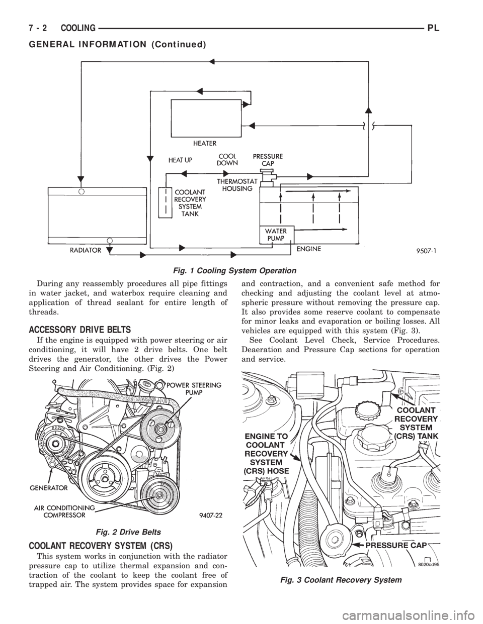
Coolant flow circuit for the 2.0L engine is shown in
(Fig. 1).
PLCOOLING 7 - 1
Page 195 of 1200
During any reassembly procedures all pipe fittings
in water jacket, and waterbox require cleaning and
application of thread sealant for entire length of
threads.
ACCESSORY DRIVE BELTS
If the engine is equipped with power steering or air
conditioning, it will have 2 drive belts. One belt
drives the generator, the other drives the Power
Steering and Air Conditioning. (Fig. 2)
COOLANT RECOVERY SYSTEM (CRS)
This system works in conjunction with the radiator
pressure cap to utilize thermal expansion and con-
traction of the coolant to keep the coolant free of
trapped air. The system provides space for expansionand contraction, and a convenient safe method for
checking and adjusting the coolant level at atmo-
spheric pressure without removing the pressure cap.
It also provides some reserve coolant to compensate
for minor leaks and evaporation or boiling losses. All
vehicles are equipped with this system (Fig. 3).
See Coolant Level Check, Service Procedures.
Deaeration and Pressure Cap sections for operation
and service.
Fig. 1 Cooling System Operation
Fig. 2 Drive Belts
Fig. 3 Coolant Recovery System
7 - 2 COOLINGPL
GENERAL INFORMATION (Continued)