1999 DODGE NEON fuse chart
[x] Cancel search: fuse chartPage 397 of 1200

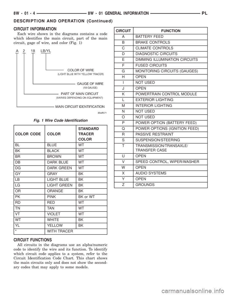
CIRCUIT INFORMATION
Each wire shown in the diagrams contains a code
which identifies the main circuit, part of the main
circuit, gage of wire, and color (Fig. 1)
CIRCUIT FUNCTIONS
All circuits in the diagrams use an alpha/numeric
code to identify the wire and its function. To identify
which circuit code applies to a system, refer to the
Circuit Identification Code Chart. This chart shows
the main circuits only and does not show the second-
ary codes that may apply to some models.
Fig. 1 Wire Code Identification
COLOR CODE COLORSTANDARD
TRACER
COLOR
BL BLUE WT
BK BLACK WT
BR BROWN WT
DB DARK BLUE WT
DG DARK GREEN WT
GY GRAY BK
LB LIGHT BLUE BK
LG LIGHT GREEN BK
OR ORANGE BK
PK PINK BK or WT
RD RED WT
TN TAN WT
VT VIOLET WT
WT WHITE BK
YL YELLOW BK
* WITH TRACER
CIRCUIT FUNCTION
A BATTERY FEED
B BRAKE CONTROLS
C CLIMATE CONTROLS
D DIAGNOSTIC CIRCUITS
E DIMMING ILLUMINATION CIRCUITS
F FUSED CIRCUITS
G MONITORING CIRCUITS (GAUGES)
H OPEN
I NOT USED
J OPEN
K POWERTRAIN CONTROL MODULE
L EXTERIOR LIGHTING
M INTERIOR LIGHTING
N NOT USED
O NOT USED
P POWER OPTION (BATTERY FEED)
Q POWER OPTIONS (IGNITION FEED)
R PASSIVE RESTRAINT
S SUSPENSION/STEERING
T TRANSMISSION/TRANSAXLE/
TRANSFER CASE
U OPEN
V SPEED CONTROL, WIPER/WASHER
W OPEN
X AUDIO SYSTEMS
Y OPEN
Z GROUNDS
8W - 01 - 4 8W - 01 GENERAL INFORMATIONPL
DESCRIPTION AND OPERATION (Continued)
Page 413 of 1200

NOT
USEDFUEL
PUMP
RELAYAUTO
SHUT
DOWN
RELAYHORN
RELAY
A/C
COMPRESSOR
CLUTCH
RELAYENGINE
STARTER
MOTOR
RELAY
FUSE
25
13 FUSE
16 FUSE
FUSE
1823 FUSE
FUSE
21
20 FUSE
FUSE 10 FUSE 11
FUSE 2 FUSE 3
FUSE 5
FUSE 8
TOP OF
POWER DISTRIBUTION CENTER
PDC FUSE APPLICATION CHART
FUSE NO. AMPS CIRCUIT FUNCTION
240A A2 12PK/BK FUSED B(+)
A3 12RD/WT
A16 14GY 40A
3
530A
A4 14BK/RD
A20 12RD/DG 30A
8
A1 14RD 40A
10
1130A
M1 18PK
1310A
M1 18PK
INTERNAL F61 18WT/OR
20A
16 *
2010A
INTERNAL 1820A
L9 18BK/WT
INTERNAL 20A
21
F32 18PK/DB 15A
23
15A
25INTERNAL RELAYLAMPFOG
RELAYLAMP WARNINGABS
16 **--FUSED B(+)
FUSED B(+)
FUSED B(+)
FUSED B(+)
FUSED B(+)
FUSED B(+)
FUSED B(+)
NOT USED
FUSED B(+)
FUSED B(+)
FUSED B(+)
FUSED B(+)
FUSED B(+)
FUSED B(+)
FUSED B(+)
* BUILT-UP-EXPORT
** EXCEPT BUILT-UP-EXPORT
8W - 10 - 2 8W-10 POWER DISTRIBUTIONPL
J988W-18188
Page 414 of 1200

48
51
504947
444542
46
4338
41
394037
525455
56
5358
61
576059
72
343532
36
33
71
626564
63
66
28
31
27302970
2221 20
19
17 18 23
24
15 16 25
26
14 13
1211
9
10
1 2 43
65
87
73
BOTTOM OF
POWER DISTRIBUTION CENTER
INTERNAL F61 18WT/OR
16 *
CAV CIRCUIT FUNCTION
2 A2 12PK/BK FUSED B(+)
A3 12RD/WT
A16 14GY 5
8 A4 14BK/RD
A20 12RD/DG 10
M1 18PK
13
M1 18PK
18 INTERNAL
F32 18PK/DB L9 18BK/WT 20 3
25
FUSED B(+)
FUSED B(+)
FUSED B(+)
FUSED B(+)
FUSED B(+)
FUSED B(+)
FUSED B(+)
FUSED B(+)
FUSED B(+)
FUSED B(+)
FUSED B(+)
PDC FUSE PIN-OUT CHART
* BUILT-UP-EXPORT
11A1 14RD
INTERNALFUSED B(+)
FUSED B(+)
21
INTERNAL
FUSED B(+) A14 16RD/WT FUSED B(+)
23FUSED B(+)
INTERNAL
PL8W-10 POWER DISTRIBUTION 8W - 10 - 3
8192J988W-1
Page 415 of 1200

48
51
504947
444542
46
4338
41
394037
525455
56
5358
61
576059
72
343532
36
33
71
626564
63
66
28
31
27302970
2221 20
19
17 18 23
24
15 16 25
26
14 13
1211
9
10
1 2 43
65
87
73
FUEL PUMP RELAY CONTROL 53 K31 18BR
60 AUTOMATIC SHUT DOWN RELAY OUTPUT
X2 18DG/RD
63HORN RELAY OUTPUT
INTERNAL 66 FUSED B(+)
70 A1 14RD
71 F12 18DG/WT FUSED IGNITION (START-RUN)
A14 16RD/WT FUSED B(+)
A0 8RD 73 B(+) 72A141 16DG/WT FUEL PUMP RELAY OUTPUT 52
61A142 18DG/OR
K51 18DB/YL AUTOMATIC SHUT DOWN RELAY CONTROL
FUSED B(+) A/C COMPRESSOR CLUTCH RELAY CONTROL GROUND Z1 18BK T41 18BR/YL
31 *** 28 *** FUSED IGNITION (START)T141 14YL/RD
40
GROUND 41 Z1 18BKABS WARNING LAMP RELAY CONTROL B58 18GY/LB C28 18DB/OR 36A/C COMPRESSOR CLUTCH RELAY OUTPUT 35 C3 16DB/BKFUSED B(+)
32INTERNALPARK/NEUTRAL POSITION SWITCH SENSE 31 **A41 14YL 28 ** FUSED IGNITION (START)
T40 14BR 30 ENGINE STARTER MOTOR RELAY OUTPUT
FUNCTION CIRCUIT CAVBOTTOM OF POWER DISTRIBUTION CENTER
39
A17 18RD/BK FUSED B(+) TO BRAKE CONTROLLER
G19 20LG/BR ABS WARNING LAMP DRIVER
X2 18DG/RD *
HORN RELAY OUTPUT
42
43
45
46F61 18WT/OR
L35 18BR/RD
L39 18LB/WT
Z1 18BKFUSED B(+)
FOG LAMP RELAY CONTROL
FOG LAMP RELAY OUTPUT
GROUND
37 INTERNAL FUSED IGNITION (ST-RUN)
27 INTERNAL FUSED B(+)
33 F12 18DG/WT FUSED IGNITION (ST-RUN)
55
56INTERNAL FUSED B(+)
F12 18DG/WT FUSED IGNITION (ST-RUN)
58 INTERNAL FUSED B(+) 57 INTERNAL FUSED B(+)
62 INTERNAL FUSED B(+)
65 X3 18BK/RD HORN RELAY CONTROL
* BUILT-UP-EXPORT
PDC RELAY PIN-OUT CHART
** ATX
*** MTX
8W - 10 - 4 8W-10 POWER DISTRIBUTIONPL
J988W-18193
Page 1141 of 1200

(3) Close all doors, windows and vents to the pas-
senger compartment.
(4) Set Heater-A/C control to A/C, full heat, floor,
RECIRC. and high blower.
(5) Start the engine and hold the idle speed (1000
rpm). After the engine has reached running temper-
ature, allow the passenger compartment to heat up.
This will create the need for maximum refrigerant
flow into the evaporator.
(6) If the refrigerant charge is sufficient, discharge
(high pressure) gauge should read 965 to 2620 kPa
(140 to 380 psi). Suction (low pressure) gauge should
read 103 to 2417 kPa (15 to 35 psi). If system cannot
achieve proper pressure readings, replace the expan-
sion valve. If pressure is correct, proceed with test.
WARNING: PROTECT SKIN AND EYES FROM CON-
TACTING CO2 PERSONAL INJURY CAN RESULT.
(7) If suction side low pressure is within specified
range, freeze the expansion valve control head (Fig.
10) for 30 seconds. Use a super cold substance (liquid
CO2).Do not spray refrigerant on the expansion
valve for this test.Suction side low pressure should
drop to 34.5 kPa (5 psi) If not, replace expansion
valve.
(8) Allow expansion valve to thaw. The low pres-
sure gauge reading should stabilize at 103 to 241
kPa (15 to 35 psi). If not, replace expansion valve.
(9) When expansion valve test is complete, test
A/C overall performance. Refer to the Heater and A/C
Performance Test in this section. Remove all test
equipment before returning vehicle to use.
BLOWER MOTOR ELECTRICAL DIAGNOSIS
Refer to the Blower Motor Electrical System Diag-
nosis chart in this section. Also refer to Group 8W,
Wiring Diagrams for more information.
BLOWER MOTOR VIBRATION AND/OR NOISE
DIAGNOSIS
The resistor block supplies the blower motor with
varied voltage (low and middle speeds) or battery
voltage (high speed).
CAUTION: Stay clear of the blower motor and resis-
tor block (Hot). Do not operate the blower motor
with the resistor block removed from the heater-A/C
housing.
Refer to the Blower Motor Vibration/Noise chart
for diagnosis.
EVAPORATOR PROBE TEST
The work area and vehicle must be between 16É C
(60É F) and 32É C (90É F) when testing the switch.(1) Disconnect the three wire connector from the
evaporator probe lead located behind the glove box.
(2) Start engine and set A/C to low blower motor
speed, panel, full cool, and RECIRC.
(3) Using a voltmeter, check for battery voltage
between Pin 1 and 2. If no voltage is detected, there
is no power to the switch. Check wiring and fuses.
Refer to Group 8W, Wiring Diagrams for circuit diag-
nosis.
(4) Using a voltmeter, check for battery voltage
between Pin 1 and Pin 3. If no voltage is detected,
there is no voltage from the Powertrain Control Mod-
ule. Refer to Group 8W, Wiring Diagrams. If voltage
is OK, connect a jumper wire between Pin 1 and Pin
3. The compressor clutch should engage. If the clutch
engages, remove the jumper wire immediately and go
to Step 5. If the compressor clutch does not engage,
check the operation of the clutch and repair as nec-
essary.
(5) If compressor clutch engages, connect the evap-
orator probe 3-way connector. The compressor clutch
should engage or cycle depending on evaporator tem-
perature. If OK, go to Step 6. If not OK, replace the
clutch cycling switch.
(6) The engine running and the A/C set to:
²Blower motor on low speed
²Panel position
²Full cool
²RECIRC.
Close all doors and windows. Place a thermometer
in the center discharge vent.
(7) If the clutch does not begin to cycle off between
2É C to 7É C (35É F to 45É F), verify that the evapo-
rator probe is fully installed and not loose in evapo-
rator. If it is not properly installed, install probe and
retest outlet temperature. If the evaporator probe is
properly installed, replace the clutch cycling switch.
HEATER PERFORMANCE TEST
PRE-DIAGNOSTIC PREPARATIONS
Review Safety Precautions and Warnings in this
group before performing the following procedures.
Check the coolant level, drive belt tension, vacuum
line connections, radiator air flow and fan operation.
Start engine and allow to warm up to normal tem-
perature.
WARNING: DO NOT REMOVE RADIATOR CAP
WHEN ENGINE IS HOT, PERSONAL INJURY CAN
RESULT.
If vehicle has been run recently, wait 15 minutes
before removing cap. Place a rag over the cap and
turn it to the first safety stop. Allow pressure to
escape through the overflow tube. When the system
stabilizes, remove the cap completely.
24 - 8 HEATING AND AIR CONDITIONINGPL
DIAGNOSIS AND TESTING (Continued)