1999 DODGE NEON manual radio set
[x] Cancel search: manual radio setPage 271 of 1200

When the ignition switch is in the OFF position, or
when the radio frequency is being displayed, time
keeping is accurately maintained.
The procedure for setting the clock varies slightly
with each radio. The correct procedure is described in
the individual radio operating instructions. Refer to
the Owner's Manual supplied with the vehicle.
INSTRUMENT CLUSTER
There are two conventional instrument cluster
assemblies available. The clusters electronically drive
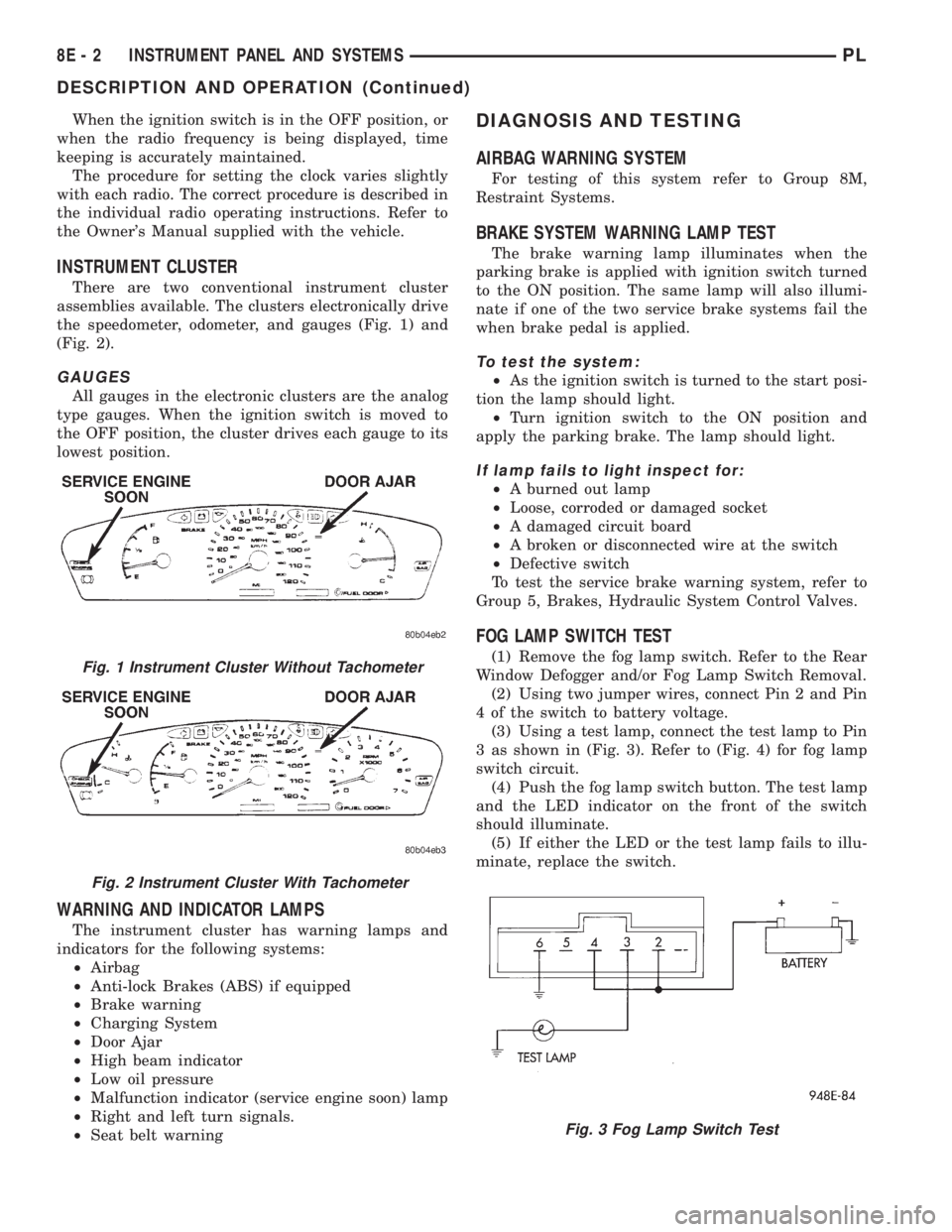
the speedometer, odometer, and gauges (Fig. 1) and
(Fig. 2).
GAUGES
All gauges in the electronic clusters are the analog
type gauges. When the ignition switch is moved to
the OFF position, the cluster drives each gauge to its
lowest position.
WARNING AND INDICATOR LAMPS
The instrument cluster has warning lamps and
indicators for the following systems:
²Airbag
²Anti-lock Brakes (ABS) if equipped
²Brake warning
²Charging System
²Door Ajar
²High beam indicator
²Low oil pressure
²Malfunction indicator (service engine soon) lamp
²Right and left turn signals.
²Seat belt warning
DIAGNOSIS AND TESTING
AIRBAG WARNING SYSTEM
For testing of this system refer to Group 8M,
Restraint Systems.
BRAKE SYSTEM WARNING LAMP TEST
The brake warning lamp illuminates when the
parking brake is applied with ignition switch turned
to the ON position. The same lamp will also illumi-
nate if one of the two service brake systems fail the
when brake pedal is applied.
To test the system:
²As the ignition switch is turned to the start posi-
tion the lamp should light.
²Turn ignition switch to the ON position and
apply the parking brake. The lamp should light.
If lamp fails to light inspect for:
²A burned out lamp
²Loose, corroded or damaged socket
²A damaged circuit board
²A broken or disconnected wire at the switch
²Defective switch
To test the service brake warning system, refer to
Group 5, Brakes, Hydraulic System Control Valves.
FOG LAMP SWITCH TEST
(1) Remove the fog lamp switch. Refer to the Rear
Window Defogger and/or Fog Lamp Switch Removal.
(2) Using two jumper wires, connect Pin 2 and Pin
4 of the switch to battery voltage.
(3) Using a test lamp, connect the test lamp to Pin
3 as shown in (Fig. 3). Refer to (Fig. 4) for fog lamp
switch circuit.
(4) Push the fog lamp switch button. The test lamp
and the LED indicator on the front of the switch
should illuminate.
(5) If either the LED or the test lamp fails to illu-
minate, replace the switch.Fig. 1 Instrument Cluster Without Tachometer
Fig. 2 Instrument Cluster With Tachometer
Fig. 3 Fog Lamp Switch Test
8E - 2 INSTRUMENT PANEL AND SYSTEMSPL
DESCRIPTION AND OPERATION (Continued)
Page 288 of 1200

AUDIO SYSTEM
CONTENTS
page page
GENERAL INFORMATION
INTRODUCTION......................... 1
DESCRIPTION AND OPERATION
INTERFERENCE ELIMINATION.............. 1
DIAGNOSIS AND TESTING
ANTENNA.............................. 3
AUDIO DIAGNOSTIC TEST PROCEDURES..... 1BENCH TEST FOR ANTENNA MALFUNCTION . . 3
REMOVAL AND INSTALLATION
ANTENNA.............................. 3
FRONT DOOR SPEAKER................... 4
INSTRUMENT PANEL SPEAKER............. 4
RADIO................................. 4
REAR SHELF SPEAKER(S)................. 5
GENERAL INFORMATION
INTRODUCTION
Operating instructions for the factory installed
audio systems can be found in the Owner's Manual
provided with the vehicle.
The vehicles are equipped with an Interior (Igni-
tion Off Draw) fuse in the Power Distribution Center
located in the engine compartment. After the Interior
(IOD) fuse or battery has been disconnected the clock
will require resetting.
DESCRIPTION AND OPERATION
INTERFERENCE ELIMINATION
The radio utilizes a ground wire plugged on to a
blade terminal and is bolted to the radio chassis.
Both connector and terminal should be securely
attached. The engine has three separate ground
straps to suppress ignition noise which may interfere
with radio reception.
²Left engine mount clip on strap
²Engine to shock tower reinforcement
²Rear strut to body, clip-on strap
Inductive type spark plug cables in the high ten-
sion circuit of the ignition system complete the inter-
ference suppression. Faulty or deteriorated spark
plug wires should be replaced.
In addition, there is a capacitor mounted on the
cylinder head which also helps suppress ignition
noise.
DIAGNOSIS AND TESTING
AUDIO DIAGNOSTIC TEST PROCEDURES
CAUTION: The CD player will only operate between
approximate temperatures of -23ÉC and +65ÉC (-10ÉF
and +145ÉF).
Whenever a radio malfunction occurs;
(1) First check FUSES:
(a) Power Distribution Center (PDC), Interior
lamp fuse, M1 - Radio Memory Feed
(b) Fuse Block:
(I) Fuse 12, Illumination in the fuse block
(II) Fuse 16, Ignition feed in the fuse block
NOTE: The vehicles are shipped with the INTERIOR
LAMP fuse disconnected.
(2) Verify, the radio wire harness are properly con-
nected before starting normal diagnosis and repair
procedures. Refer to Audio Diagnosis table and/or
Group 8W, Wiring Diagrams, Radio Section.
PLAUDIO SYSTEM 8F - 1
Page 943 of 1200

CAUTION: Do not install steering wheel onto shaft
of steering column assembly by driving it onto the
shaft. Pull steering wheel down onto steering col-
umn shaft using ONLY the steering wheel retaining
nut.
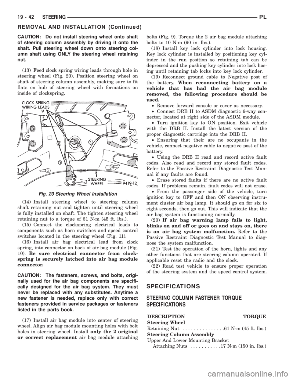
(13) Feed clock spring wiring leads through hole in
steering wheel (Fig. 20). Position steering wheel on
shaft of steering column assembly, making sure to fit
flats on hub of steering wheel with formations on
inside of clockspring.
(14) Install steering wheel to steering column
shaft retaining nut and tighten until steering wheel
is fully installed on shaft. The tighten steering wheel
retaining nut to a torque of 61 N´m (45 ft. lbs.).
(15) Connect the clockspring electrical leads to
components such as horn switches and speed control
switches located in the steering wheel (Fig. 11).
(16) Install air bag electrical lead from clock
spring, into connector on back of air bag module (Fig.
10).Be sure electrical connector from clock-
spring is securely latched into air bag module
connector.
CAUTION: The fasteners, screws, and bolts, origi-
nally used for the air bag components are specifi-
cally designed for the air bag system. They must
never be replaced with any substitutes. Anytime a
new fastener is needed, replace only with correct
fasteners provided in service packages or fasteners
listed in the parts book.
(17) Install air bag module into center of steering
wheel. Align air bag module mounting holes with bolt
holes in steering wheel. Installonly the 2 original
or correct replacementair bag module attachingbolts (Fig. 9). Torque the 2 air bag module attaching
bolts to 10 N´m (90 in. lbs.).
(18) Install key lock cylinder into lock housing.
Key lock cylinder is installed by positioning key cyl-
inder in the run position so retaining tab can be
depressed and the pushing key cylinder into lock hos-
ing until retaining tab locks into key lock cylinder.
(19) Reconnect ground cable to Negative post of
the battery.When reconnecting battery on a
vehicle that has had the air bag module
removed, the following procedure should be
used.
²Remove forward console or cover as necessary.
²Connect DRB II to ASDM diagnostic 6-way con-
nector, located at right side of the ASDM module.
²Turn ignition key to ON position. Exit vehicle
with the DRB II. Install the latest version of the
proper diagnostic cartridge into the DRB II.
²Ensuring that their are no occupants in the
vehicle, connect negative cable to negative post of the
battery.
²Using the DRB II read and record active fault
codes. Also read and record any stored fault codes.
Refer to the Passive Restraint Diagnostic Test Man-
ual if any faults are found.
²Erase stored faults if there are no active fault
codes. If problems remain, fault codes will not erase.
²From the passenger side of the vehicle, turn
ignition key to OFF and then ON observing instru-
ment cluster air bag lamp. It should go on for six to
eight seconds, then go out. This will indicate that the
air bag system is functioning normally.
(20)If air bag warning lamp fails to light,
blinks on and off or goes on and stays on, there
is an air bag system malfunction.Refer to the
Passive Restraint Diagnostic Test Manual to diag-
nose the system malfunction.
(21) Test the operation of the horn, lights and any
other functions that are steering column operated. If
applicable reset the radio and the clock.
(22) Road test vehicle to ensure proper operation
of the steering system and the speed control system.
SPECIFICATIONS
STEERING COLUMN FASTENER TORQUE
SPECIFICATIONS
DESCRIPTION TORQUE
Steering Wheel
Retaining Nut...............61N´m(45ft.lbs.)
Steering Column Assembly
Upper And Lower Mounting Bracket
Attaching Nuts...........17N´m(150 in. lbs.)
Fig. 20 Steering Wheel Installation
19 - 42 STEERINGPL
REMOVAL AND INSTALLATION (Continued)