1999 DODGE NEON OBD port
[x] Cancel search: OBD portPage 236 of 1200

CHARGING SYSTEM
CONTENTS
page page
GENERAL INFORMATION
OVERVIEW............................. 1
DESCRIPTION AND OPERATION
BATTERY TEMPERATURE SENSOR.......... 2
CHARGING SYSTEM OPERATION........... 1
ELECTRONIC VOLTAGE REGULATOR......... 2
GENERATOR............................ 2
DIAGNOSIS AND TESTING
BATTERY TEMPERATURE SENSOR.......... 8
CHARGING SYSTEM RESISTANCE TESTS..... 5CHARGING SYSTEM...................... 2
CURRENT OUTPUT TEST.................. 8
ON-BOARD DIAGNOSTIC SYSTEM TEST..... 10
REMOVAL AND INSTALLATION
BATTERY TEMPERATURE SENSOR......... 11
GENERATOR........................... 10
SPECIFICATIONS
GENERATOR RATINGS................... 12
TORQUE.............................. 12
GENERAL INFORMATION
OVERVIEW
The battery, starting, and charging systems oper-
ate with one another, and must be tested as a com-
plete system. In order for the vehicle to start and
charge properly, all of the components involved in
these systems must perform within specifications.
Group 8A covers the battery, Group 8B covers the
starting system, and Group 8C covers the charging
system. Refer to Group 8W - Wiring Diagrams for
complete circuit descriptions and diagrams. We have
separated these systems to make it easier to locate
the information you are seeking within this Service
Manual. However, when attempting to diagnose any
of these systems, it is important that you keep their
interdependency in mind.
The diagnostic procedures used in these groups
include the most basic conventional diagnostic meth-
ods to the more sophisticated On-Board Diagnostics
(OBD) built into the Powertrain Control Module
(PCM). Use of an induction ammeter, volt/ohmmeter,
battery charger, carbon pile rheostat (load tester),
and 12-volt test lamp may be required.
All OBD-sensed systems are monitored by the
PCM. Each monitored circuit is assigned a Diagnos-
tic Trouble Code (DTC). The PCM will store a DTC in
electronic memory for any failure it detects. See the
On-Board Diagnostics Test in Group 8C - Charging
System for more information.
DESCRIPTION AND OPERATION
CHARGING SYSTEM OPERATION
The charging system consists of:
²Generator
²Electronic Voltage Regulator (EVR) circuitry
within the Powertrain Control Module (PCM)
²Ignition switch (refer to Group 8D, Ignition Sys-
tem for information)
²Battery (refer to Group 8A, Battery for informa-
tion)
²Battery temperature sensor
²Voltmeter (refer to Group 8E, Instrument Panel
and Gauges for information)
²Wiring harness and connections (refer to Group
8W, Wiring for information)
The charging system is turned on and off with the
ignition switch. When the ignition switch is turned to
the ON position, battery voltage is applied to the
generator rotor through one of the two field termi-
nals to produce a magnetic field. The generator is
driven by the engine through a serpentine belt and
pulley arrangement.
The amount of DC current produced by the gener-
ator is controlled by the EVR (field control) circuitry,
contained within the PCM. This circuitry is con-
nected in series with the second rotor field terminal
and ground.
PLCHARGING SYSTEM 8C - 1
Page 245 of 1200

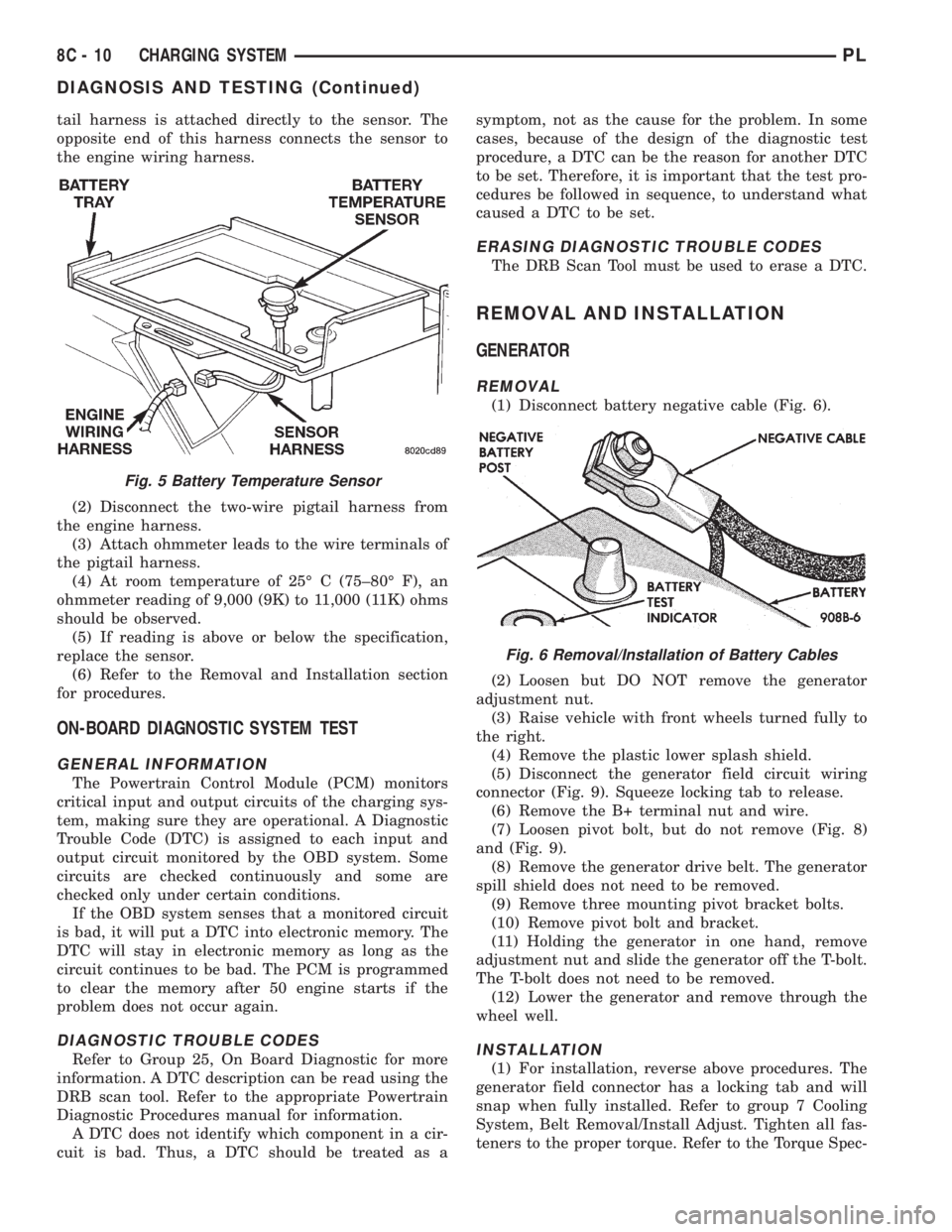
tail harness is attached directly to the sensor. The
opposite end of this harness connects the sensor to
the engine wiring harness.
(2) Disconnect the two-wire pigtail harness from
the engine harness.
(3) Attach ohmmeter leads to the wire terminals of
the pigtail harness.
(4) At room temperature of 25É C (75±80É F), an
ohmmeter reading of 9,000 (9K) to 11,000 (11K) ohms
should be observed.
(5) If reading is above or below the specification,
replace the sensor.
(6) Refer to the Removal and Installation section
for procedures.
ON-BOARD DIAGNOSTIC SYSTEM TEST
GENERAL INFORMATION
The Powertrain Control Module (PCM) monitors
critical input and output circuits of the charging sys-
tem, making sure they are operational. A Diagnostic
Trouble Code (DTC) is assigned to each input and
output circuit monitored by the OBD system. Some
circuits are checked continuously and some are
checked only under certain conditions.
If the OBD system senses that a monitored circuit
is bad, it will put a DTC into electronic memory. The
DTC will stay in electronic memory as long as the
circuit continues to be bad. The PCM is programmed
to clear the memory after 50 engine starts if the
problem does not occur again.
DIAGNOSTIC TROUBLE CODES
Refer to Group 25, On Board Diagnostic for more
information. A DTC description can be read using the
DRB scan tool. Refer to the appropriate Powertrain
Diagnostic Procedures manual for information.
A DTC does not identify which component in a cir-
cuit is bad. Thus, a DTC should be treated as asymptom, not as the cause for the problem. In some
cases, because of the design of the diagnostic test
procedure, a DTC can be the reason for another DTC
to be set. Therefore, it is important that the test pro-
cedures be followed in sequence, to understand what
caused a DTC to be set.
ERASING DIAGNOSTIC TROUBLE CODES
The DRB Scan Tool must be used to erase a DTC.
REMOVAL AND INSTALLATION
GENERATOR
REMOVAL
(1) Disconnect battery negative cable (Fig. 6).
(2) Loosen but DO NOT remove the generator
adjustment nut.
(3) Raise vehicle with front wheels turned fully to
the right.
(4) Remove the plastic lower splash shield.
(5) Disconnect the generator field circuit wiring
connector (Fig. 9). Squeeze locking tab to release.
(6) Remove the B+ terminal nut and wire.
(7) Loosen pivot bolt, but do not remove (Fig. 8)
and (Fig. 9).
(8) Remove the generator drive belt. The generator
spill shield does not need to be removed.
(9) Remove three mounting pivot bracket bolts.
(10) Remove pivot bolt and bracket.
(11) Holding the generator in one hand, remove
adjustment nut and slide the generator off the T-bolt.
The T-bolt does not need to be removed.
(12) Lower the generator and remove through the
wheel well.
INSTALLATION
(1) For installation, reverse above procedures. The
generator field connector has a locking tab and will
snap when fully installed. Refer to group 7 Cooling
System, Belt Removal/Install Adjust. Tighten all fas-
teners to the proper torque. Refer to the Torque Spec-
Fig. 5 Battery Temperature Sensor
Fig. 6 Removal/Installation of Battery Cables
8C - 10 CHARGING SYSTEMPL
DIAGNOSIS AND TESTING (Continued)
Page 300 of 1200

The individual switches cannot be repaired. If one
switch fails, the entire switch module must be
replaced.
STOP LAMP SWITCH
Vehicles equipped with the speed control option use
a dual function stop lamp switch. The switch is
mounted on the brake pedal mounting bracket under
the instrument panel. The PCM monitors the state of
the dual function stop lamp switch. Refer to Group 5,
Brakes for more information on stop lamp switch ser-
vice and adjustment procedures.
SERVO CABLE
The speed control servo cable is connected between
the speed control vacuum servo diaphragm and the
throttle body control linkage. This cable causes the
throttle control linkage to open or close the throttle
valve in response to movement of the vacuum servo
diaphragm.
POWERTRAIN CONTROL MODULE
The speed control electronic control circuitry is
integrated into the Powertrain Control Module
(PCM). The PCM is located in the engine compart-
ment. The PCM speed control functions are moni-
tored by the On-Board Diagnostics (OBD). All OBD-
sensed systems are monitored by the PCM. Each
monitored circuit is assigned a Diagnostic Trouble
Code (DTC). The PCM will store a DTC in electronic
memory for any failure it detects. See On-Board
Diagnostic Tests in this group for more information.
The PCM cannot be repaired and must be replaced if
faulty.
USE THE DRB SCAN TOOL TO REPROGRAM
THE NEW PCM WITH THE VEHICLES ORIGI-
NAL IDENTIFICATION NUMBER (VIN) AND
THE ORIGINAL VEHICLES MILEAGE. IF THIS
STEP IS NOT DONE A DIAGNOSTIC TROUBLE
CODE (DTC) MAY BE SET.
VACUUM RESERVOIR
The reservoir contains a one-way check valve to
trap engine vacuum in the reservoir. When engine
vacuum drops, as in climbing a grade while driving,
the reservoir supplies the vacuum needed to main-
tain proper speed control operation. The vacuum res-
ervoir cannot be repaired and must be replaced if
faulty.
VEHICLE SPEED AND DISTANCE
The 4 speed automatic Transmission Control Mod-
ule (TCM) supplies the speed input to the PCM. The
PCM determines acceleration rates. The speed con-
trol software in the PCM uses vehicle speed and
acceleration to control to the set speed.Vehicles with a 3 speed automatic or manual trans-
mission have a vehicle speed sensor (VSS) mounted
to an adapter near the transmission output shaft.
The sensor is driven through the adapter by a speed-
ometer pinion gear. The VSS pulse signal is moni-
tored by the PCM to determine vehicle speed and to
maintain speed control set speed. Refer to the appro-
priate Powertrain Diagnostic Procedures manual for
diagnosis and testing of this component. Refer to
group 14, Fuel System for Removal/Installation
DIAGNOSIS AND TESTING
ROAD TEST
Perform a vehicle road test to verify reports of
speed control system malfunction. The road test
should include attention to the speedometer. Speed-
ometer operation should be smooth and without flut-
ter at all speeds.
Flutter in the speedometer indicates a problem
which might cause surging in the speed control sys-
tem. The cause of any speedometer problems should
be corrected before proceeding. Refer to Group 8E,
Instrument Panel and Gauges for speedometer diag-
nosis.
If a road test verifies a surge following a set and
the speedometer operates properly see ªOvershoot/
Undershoot on speed control setº.
If a road test verifies an inoperative system, and
the speedometer operates properly, check for:
²A Diagnostic Trouble Code (DTC). If a DTC
exists, conduct tests per the Powertrain Diagnostic
Procedures service manual.
²A misadjusted brake (stop) lamp switch. This
could also cause an intermittent problem.
²Loose or corroded electrical connections at the
servo. Corrosion should be removed from electrical
terminals and a light coating of Mopar Multipurpose
Grease, or equivalent, applied.
²Leaking vacuum reservoir.
²Loose or leaking vacuum hoses or connections.
²Defective one-way vacuum check valve.
²Secure attachment at both ends of the speed
control servo cable.
²Smooth operation of throttle linkage and throttle
body air valve.
²Conduct electrical test at PCM.
²Failed speed control servo. Do the servo vacuum
test.
CAUTION: When test probing for voltage or conti-
nuity at electrical connectors, care must be taken
not to damage connector, terminals or seals. If
these components are damaged, intermittent or
complete system failure may occur.
PLVEHICLE SPEED CONTROL SYSTEM 8H - 3
DESCRIPTION AND OPERATION (Continued)