1999 DODGE NEON clock
[x] Cancel search: clockPage 47 of 1200
ADJUSTMENTS
STRUT ADJUSTMENT COMPETITION PACKAGE
SUSPENSION
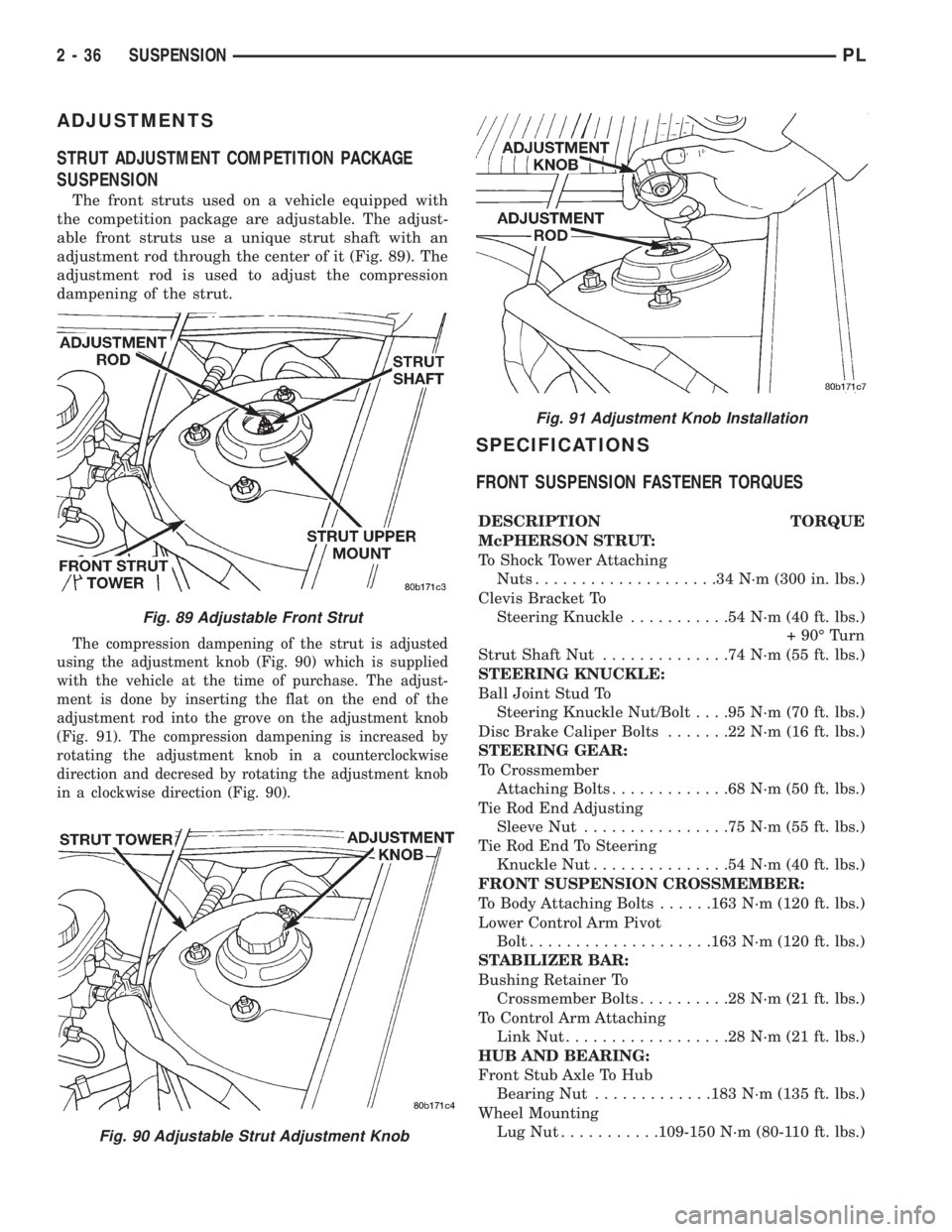
The front struts used on a vehicle equipped with
the competition package are adjustable. The adjust-
able front struts use a unique strut shaft with an
adjustment rod through the center of it (Fig. 89). The
adjustment rod is used to adjust the compression
dampening of the strut.
The compression dampening of the strut is adjusted
using the adjustment knob (Fig. 90) which is supplied
with the vehicle at the time of purchase. The adjust-
ment is done by inserting the flat on the end of the
adjustment rod into the grove on the adjustment knob
(Fig. 91). The compression dampening is increased by
rotating the adjustment knob in a counterclockwise
direction and decresed by rotating the adjustment knob
in a clockwise direction (Fig. 90).
SPECIFICATIONS
FRONT SUSPENSION FASTENER TORQUES
DESCRIPTION TORQUE
McPHERSON STRUT:
To Shock Tower Attaching
Nuts....................34N´m(300 in. lbs.)
Clevis Bracket To
Steering Knuckle...........54N´m(40ft.lbs.)
+ 90É Turn
Strut Shaft Nut..............74N´m(55ft.lbs.)
STEERING KNUCKLE:
Ball Joint Stud To
Steering Knuckle Nut/Bolt. . . .95 N´m (70 ft. lbs.)
Disc Brake Caliper Bolts.......22N´m(16ft.lbs.)
STEERING GEAR:
To Crossmember
Attaching Bolts.............68N´m(50ft.lbs.)
Tie Rod End Adjusting
Sleeve Nut................75N´m(55ft.lbs.)
Tie Rod End To Steering
Knuckle Nut...............54N´m(40ft.lbs.)
FRONT SUSPENSION CROSSMEMBER:
To Body Attaching Bolts......163 N´m (120 ft. lbs.)
Lower Control Arm Pivot
Bolt....................163 N´m (120 ft. lbs.)
STABILIZER BAR:
Bushing Retainer To
Crossmember Bolts..........28N´m(21ft.lbs.)
To Control Arm Attaching
Link Nut..................28N´m(21ft.lbs.)
HUB AND BEARING:
Front Stub Axle To Hub
Bearing Nut.............183 N´m (135 ft. lbs.)
Wheel Mounting
LugNut...........109-150 N´m (80-110 ft. lbs.)
Fig. 89 Adjustable Front Strut
Fig. 90 Adjustable Strut Adjustment Knob
Fig. 91 Adjustment Knob Installation
2 - 36 SUSPENSIONPL
Page 64 of 1200
mount and all tension is relieved from the spring
compressors.
(11) Install the strut assembly back into the vehi-
cle. Refer to Strut Assembly Removal in Servicing
Rear Struts in this section of the service manual.
(12) Check and reset rear wheel TOE to specifica-
tions if required.
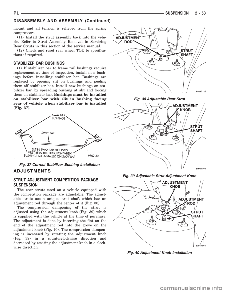
STABILIZER BAR BUSHINGS
(1) If stabilizer bar to frame rail bushings require
replacement at time of inspection, install new bush-
ings before installing stabilizer bar. Bushings are
replaced by opening slit on bushings and peeling
them off stabilizer bar. Install new bushings on sta-
bilizer bar, by spreading bushing at slit and forcing
them on stabilizer bar.Bushings must be installed
on stabilizer bar with slit in bushing facing
rear of vehicle when stabilizer bar is installed
(Fig. 37).
ADJUSTMENTS
STRUT ADJUSTMENT COMPETITION PACKAGE
SUSPENSION
The rear struts used on a vehicle equipped with
the competition package are adjustable. The adjust-
able struts use a unique strut shaft which has an
adjustment rod through the center of it (Fig. 38).
The compression dampening of the strut is
adjusted using the adjustment knob (Fig. 39) which
is supplied with the vehicle at the time of purchase.
The adjustment is done by inserting the flat on the
end of the adjustment rod into the grove on the
adjustment knob (Fig. 40). The compression dampen-
ing is increased by rotating the adjustment knob
(Fig. 39) in a counterclockwise direction and
decreased by rotating the adjustment knob in a clock-
wise direction.
Fig. 37 Correct Stabilizer Bushing Installation
Fig. 38 Adjustable Rear Strut
Fig. 39 Adjustable Strut Adjustment Knob
Fig. 40 Adjustment Knob Installation
PLSUSPENSION 2 - 53
DISASSEMBLY AND ASSEMBLY (Continued)
Page 104 of 1200
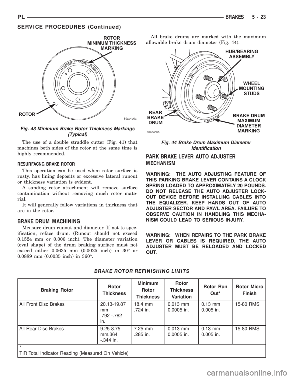
The use of a double straddle cutter (Fig. 41) that
machines both sides of the rotor at the same time is
highly recommended.
RESURFACNG BRAKE ROTOR
This operation can be used when rotor surface is
rusty, has lining deposits or excessive lateral runout
or thickness variation is evident.
A sanding rotor attachment will remove surface
contamination without removing much rotor mate-
rial.
It will generally follow variations in thickness that
are in the rotor.
BRAKE DRUM MACHINING
Measure drum runout and diameter. If not to spec-
ification, reface drum. (Runout should not exceed
0.1524 mm or 0.006 inch). The diameter variation
(oval shape) of the drum braking surface must not
exceed either 0.0635 mm (0.0025 inch) in 30É or
0.0889 mm (0.0035 inch) in 360É.All brake drums are marked with the maximum
allowable brake drum diameter (Fig. 44).
PARK BRAKE LEVER AUTO ADJUSTER
MECHANISM
WARNING: THE AUTO ADJUSTING FEATURE OF
THIS PARKING BRAKE LEVER CONTAINS A CLOCK
SPRING LOADED TO APPROXIMATELY 20 POUNDS.
DO NOT RELEASE THE AUTO ADJUSTER LOCK-
OUT DEVICE BEFORE INSTALLING CABLES INTO
THE EQUALIZER. KEEP HANDS OUT OF AUTO
ADJUSTER SECTOR AND PAWL AREA. FAILURE TO
OBSERVE CAUTION IN HANDLING THIS MECHA-
NISM COULD LEAD TO SERIOUS INJURY.
WARNING: WHEN REPAIRS TO THE PARK BRAKE
LEVER OR CABLES IS REQUIRED, THE AUTO
ADJUSTER MUST BE RELOADED AND LOCKED
OUT.
Fig. 43 Minimum Brake Rotor Thickness Markings
(Typical)
BRAKE ROTOR REFINISHING LIMITS
Braking RotorRotor
ThicknessMinimum
Rotor
ThicknessRotor
Thickness
VariationRotor Run
Out*Rotor Micro
Finish
All Front Disc Brakes 20.13-19.87
mm
.792 -.782
in.18.4 mm
.724 in.0.013 mm
0.0005 in.0.13 mm
0.005 in.15-80 RMS
All Rear Disc Brakes 9.25-8.75
mm.364
-.344 in.7.25 mm
.285 in.0.013 mm
0.0005 in.0.13 mm
0.005 in.15-80 RMS
*
TIR Total Indicator Reading (Measured On Vehicle)
Fig. 44 Brake Drum Maximum Diameter
Identification
PLBRAKES 5 - 23
SERVICE PROCEDURES (Continued)
Page 129 of 1200
PARK BRAKE LEVER ASSEMBLY
WARNING: THE AUTO ADJUSTING FEATURE OF
THIS PARKING BRAKE LEVER ASSEMBLY CON-
TAINS A CLOCK SPRING LOADED TO APPROXI-
MATELY 20 POUNDS. DO NOT RELEASE THE AUTO
ADJUSTER LOCKOUT DEVICE BEFORE INSTALL-
ING CABLES INTO THE EQUALIZER. KEEP HANDS
OUT OF AUTO ADJUSTER SECTOR AND PAWL
AREA. FAILURE TO OBSERVE CAUTION IN HAN-
DLING THIS MECHANISM COULD LEAD TO SERI-
OUS INJURY.
REMOVE
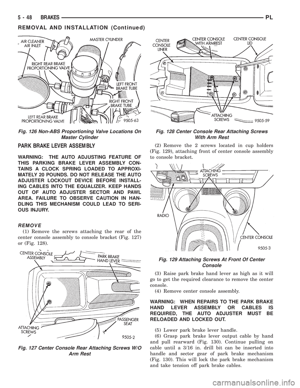
(1) Remove the screws attaching the rear of the
center console assembly to console bracket (Fig. 127)
or (Fig. 128).(2) Remove the 2 screws located in cup holders
(Fig. 129), attaching front of center console assembly
to console bracket.
(3) Raise park brake hand lever as high as it will
go to get the required clearance to remove the center
console.
(4) Remove center console assembly.
WARNING: WHEN REPAIRS TO THE PARK BRAKE
HAND LEVER ASSEMBLY OR CABLES IS
REQUIRED, THE AUTO ADJUSTER MUST BE
RELOADED AND LOCKED OUT.
(5) Lower park brake lever handle.
(6) Grasp park brake lever output cable by hand
and pull rearward (Fig. 130). Continue pulling on
cable until a 3/16 in. drill bit can be inserted into
handle and sector gear of park brake mechanism
(Fig. 130). This will lock the park brake mechanism
and take tension off park brake cables.
Fig. 126 Non-ABS Proportioning Valve Locations On
Master Cylinder
Fig. 127 Center Console Rear Attaching Screws W/O
Arm Rest
Fig. 128 Center Console Rear Attaching Screws
With Arm Rest
Fig. 129 Attaching Screws At Front Of Center
Console
5 - 48 BRAKESPL
REMOVAL AND INSTALLATION (Continued)
Page 138 of 1200
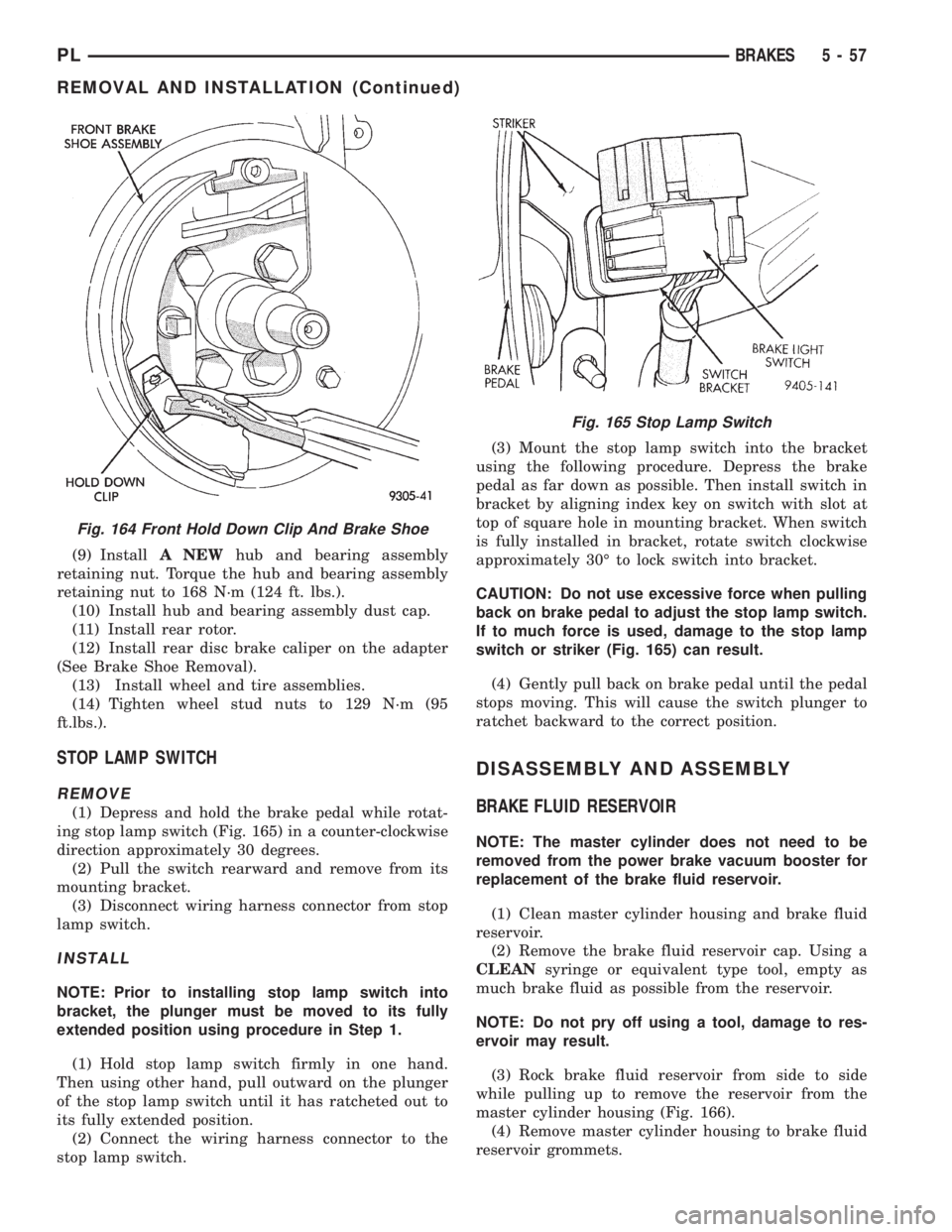
(9) InstallA NEWhub and bearing assembly
retaining nut. Torque the hub and bearing assembly
retaining nut to 168 N´m (124 ft. lbs.).
(10) Install hub and bearing assembly dust cap.
(11) Install rear rotor.
(12) Install rear disc brake caliper on the adapter
(See Brake Shoe Removal).
(13) Install wheel and tire assemblies.
(14) Tighten wheel stud nuts to 129 N´m (95
ft.lbs.).
STOP LAMP SWITCH
REMOVE
(1) Depress and hold the brake pedal while rotat-
ing stop lamp switch (Fig. 165) in a counter-clockwise
direction approximately 30 degrees.
(2) Pull the switch rearward and remove from its
mounting bracket.
(3) Disconnect wiring harness connector from stop
lamp switch.
INSTALL
NOTE: Prior to installing stop lamp switch into
bracket, the plunger must be moved to its fully
extended position using procedure in Step 1.
(1) Hold stop lamp switch firmly in one hand.
Then using other hand, pull outward on the plunger
of the stop lamp switch until it has ratcheted out to
its fully extended position.
(2) Connect the wiring harness connector to the
stop lamp switch.(3) Mount the stop lamp switch into the bracket
using the following procedure. Depress the brake
pedal as far down as possible. Then install switch in
bracket by aligning index key on switch with slot at
top of square hole in mounting bracket. When switch
is fully installed in bracket, rotate switch clockwise
approximately 30É to lock switch into bracket.
CAUTION: Do not use excessive force when pulling
back on brake pedal to adjust the stop lamp switch.
If to much force is used, damage to the stop lamp
switch or striker (Fig. 165) can result.
(4) Gently pull back on brake pedal until the pedal
stops moving. This will cause the switch plunger to
ratchet backward to the correct position.
DISASSEMBLY AND ASSEMBLY
BRAKE FLUID RESERVOIR
NOTE: The master cylinder does not need to be
removed from the power brake vacuum booster for
replacement of the brake fluid reservoir.
(1) Clean master cylinder housing and brake fluid
reservoir.
(2) Remove the brake fluid reservoir cap. Using a
CLEANsyringe or equivalent type tool, empty as
much brake fluid as possible from the reservoir.
NOTE: Do not pry off using a tool, damage to res-
ervoir may result.
(3) Rock brake fluid reservoir from side to side
while pulling up to remove the reservoir from the
master cylinder housing (Fig. 166).
(4) Remove master cylinder housing to brake fluid
reservoir grommets.
Fig. 164 Front Hold Down Clip And Brake Shoe
Fig. 165 Stop Lamp Switch
PLBRAKES 5 - 57
REMOVAL AND INSTALLATION (Continued)
Page 146 of 1200
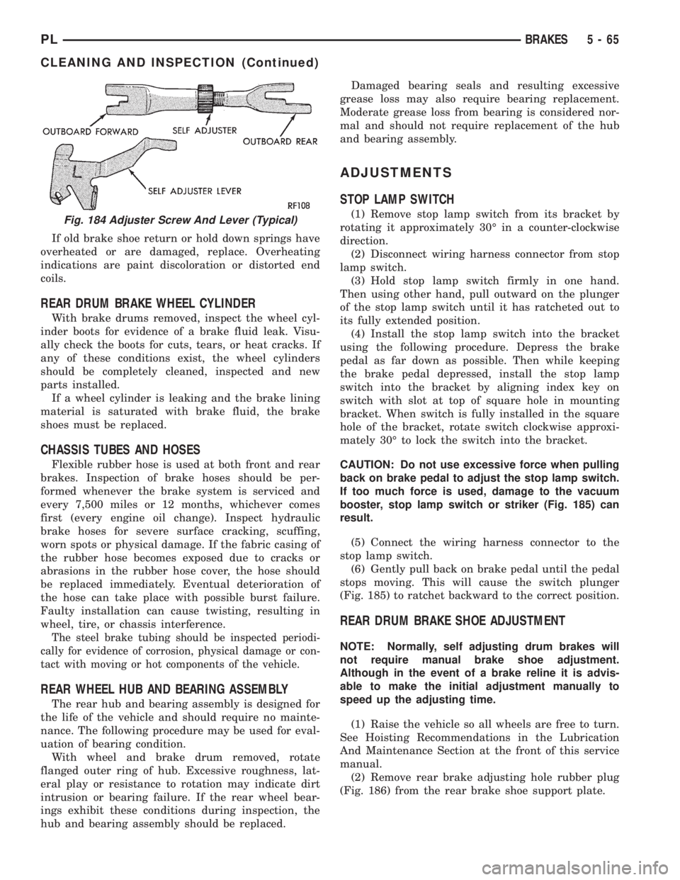
If old brake shoe return or hold down springs have
overheated or are damaged, replace. Overheating
indications are paint discoloration or distorted end
coils.
REAR DRUM BRAKE WHEEL CYLINDER
With brake drums removed, inspect the wheel cyl-
inder boots for evidence of a brake fluid leak. Visu-
ally check the boots for cuts, tears, or heat cracks. If
any of these conditions exist, the wheel cylinders
should be completely cleaned, inspected and new
parts installed.
If a wheel cylinder is leaking and the brake lining
material is saturated with brake fluid, the brake
shoes must be replaced.
CHASSIS TUBES AND HOSES
Flexible rubber hose is used at both front and rear
brakes. Inspection of brake hoses should be per-
formed whenever the brake system is serviced and
every 7,500 miles or 12 months, whichever comes
first (every engine oil change). Inspect hydraulic
brake hoses for severe surface cracking, scuffing,
worn spots or physical damage. If the fabric casing of
the rubber hose becomes exposed due to cracks or
abrasions in the rubber hose cover, the hose should
be replaced immediately. Eventual deterioration of
the hose can take place with possible burst failure.
Faulty installation can cause twisting, resulting in
wheel, tire, or chassis interference.
The steel brake tubing should be inspected periodi-
cally for evidence of corrosion, physical damage or con-
tact with moving or hot components of the vehicle.
REAR WHEEL HUB AND BEARING ASSEMBLY
The rear hub and bearing assembly is designed for
the life of the vehicle and should require no mainte-
nance. The following procedure may be used for eval-
uation of bearing condition.
With wheel and brake drum removed, rotate
flanged outer ring of hub. Excessive roughness, lat-
eral play or resistance to rotation may indicate dirt
intrusion or bearing failure. If the rear wheel bear-
ings exhibit these conditions during inspection, the
hub and bearing assembly should be replaced.Damaged bearing seals and resulting excessive
grease loss may also require bearing replacement.
Moderate grease loss from bearing is considered nor-
mal and should not require replacement of the hub
and bearing assembly.
ADJUSTMENTS
STOP LAMP SWITCH
(1) Remove stop lamp switch from its bracket by
rotating it approximately 30É in a counter-clockwise
direction.
(2) Disconnect wiring harness connector from stop
lamp switch.
(3) Hold stop lamp switch firmly in one hand.
Then using other hand, pull outward on the plunger
of the stop lamp switch until it has ratcheted out to
its fully extended position.
(4) Install the stop lamp switch into the bracket
using the following procedure. Depress the brake
pedal as far down as possible. Then while keeping
the brake pedal depressed, install the stop lamp
switch into the bracket by aligning index key on
switch with slot at top of square hole in mounting
bracket. When switch is fully installed in the square
hole of the bracket, rotate switch clockwise approxi-
mately 30É to lock the switch into the bracket.
CAUTION: Do not use excessive force when pulling
back on brake pedal to adjust the stop lamp switch.
If too much force is used, damage to the vacuum
booster, stop lamp switch or striker (Fig. 185) can
result.
(5) Connect the wiring harness connector to the
stop lamp switch.
(6) Gently pull back on brake pedal until the pedal
stops moving. This will cause the switch plunger
(Fig. 185) to ratchet backward to the correct position.
REAR DRUM BRAKE SHOE ADJUSTMENT
NOTE: Normally, self adjusting drum brakes will
not require manual brake shoe adjustment.
Although in the event of a brake reline it is advis-
able to make the initial adjustment manually to
speed up the adjusting time.
(1) Raise the vehicle so all wheels are free to turn.
See Hoisting Recommendations in the Lubrication
And Maintenance Section at the front of this service
manual.
(2) Remove rear brake adjusting hole rubber plug
(Fig. 186) from the rear brake shoe support plate.
Fig. 184 Adjuster Screw And Lever (Typical)
PLBRAKES 5 - 65
CLEANING AND INSPECTION (Continued)
Page 179 of 1200
REMOVAL
(1) Remove transaxle. See Group 21, Manual Tran-
saxle, for procedure.
(2) Mark clutch cover and flywheel, to maintain
their same relative positions when installing clutch
assembly.
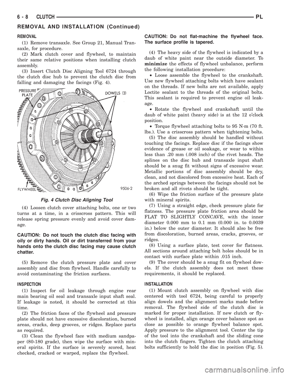
(3) Insert Clutch Disc Aligning Tool 6724 through
the clutch disc hub to prevent the clutch disc from
falling and damaging the facings (Fig. 4).
(4) Loosen clutch cover attaching bolts, one or two
turns at a time, in a crisscross pattern. This will
release spring pressure evenly and avoid cover dam-
age.
CAUTION: Do not touch the clutch disc facing with
oily or dirty hands. Oil or dirt transferred from your
hands onto the clutch disc facing may cause clutch
chatter.
(5) Remove the clutch pressure plate and cover
assembly and disc from flywheel. Handle carefully to
avoid contaminating the friction surfaces.
INSPECTION
(1) Inspect for oil leakage through engine rear
main bearing oil seal and transaxle input shaft seal.
If leakage is noted, it should be corrected at this
time.
(2) The friction faces of the flywheel and pressure
plate should not have excessive discoloration, burned
areas, cracks, deep grooves, or ridges. Replace parts
as required.
(3) Clean the flywheel face with medium sandpa-
per (80-180 grade), then wipe the surface with min-
eral spirits. If the surface is severely scored, heat
checked, cracked or warped, replace the flywheel.CAUTION: Do not flat-machine the flywheel face.
The surface profile is tapered.
(4) The heavy side of the flywheel is indicated by a
daub of white paint near the outside diameter. To
minimizethe effects of flywheel unbalance, perform
the following installation procedure:
²Loose assemble the flywheel to the crankshaft.
Use new flywheel attaching bolts which have sealant
on the threads. If new bolts are not available, apply
Loctite sealant to the threads of the original bolts.
This sealant is required to prevent engine oil leak-
age.
²Rotate the flywheel and crankshaft until the
daub of white paint (heavy side) is at the 12 o'clock
position.
²Torque flywheel attaching bolts to 95 N´m (70 ft.
lbs.). Use a crisscross pattern when tightening bolts.
(5) The disc assembly should be handled without
touching the facings. Replace disc if the facings show
evidence of grease or oil soakage, or wear to within
less than .20 mm (.008 inch) of the rivet heads. The
splines on the disc hub and transaxle input shaft
should be a snug fit without signs of excessive wear.
Metallic portions of disc assembly should be dry,
clean, and not discolored from excessive heat. Each of
the arched springs between the facings should not be
broken and all rivets should be tight.
(6) Wipe the friction surface of the pressure plate
with mineral spirits.
(7) Using a straight edge, check pressure plate for
flatness. The pressure plate friction area should be
FLAT TO SLIGHTLY CONCAVE, with the inner
diameter 0.000 mm to 0.1 mm (0.000 in. to 0.0039
in.) below the outer diameter. It should also be free
from discoloration, burned areas, cracks, grooves, or
ridges.
(8) Using a surface plate, test cover for flatness.
All sections around attaching bolt holes should be in
contact with surface plate within .015 inch.
(9) The cover should be a snug fit on flywheel dow-
els. If the clutch assembly does not meet these
requirements, it should be replaced.
INSTALLATION
(1) Mount clutch assembly on flywheel with disc
centered with tool 6724, being careful to properly
align dowels and the alignment marks made before
removal. The flywheel side of the clutch disc is
marked for proper installation. If new clutch or fly-
wheel is installed, align orange cover balance spot as
close as possible to orange flywheel balance spot.
Apply pressure to the alignment tool. Center the tip
of the tool into the crankshaft and the sliding cone
into the clutch fingers. Tighten the clutch attaching
bolts sufficiently to hold the disc in position (Fig. 5).
Fig. 4 Clutch Disc Aligning Tool
6 - 8 CLUTCHPL
REMOVAL AND INSTALLATION (Continued)
Page 190 of 1200
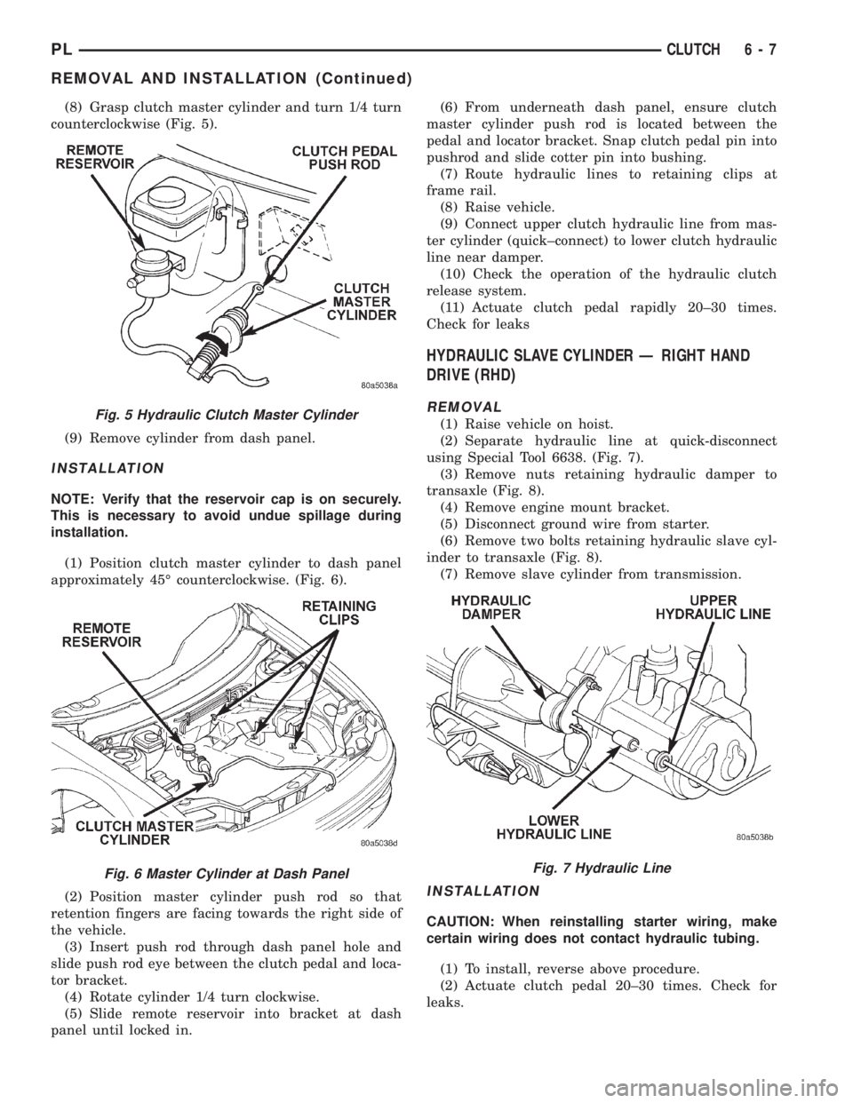
(8) Grasp clutch master cylinder and turn 1/4 turn
counterclockwise (Fig. 5).
(9) Remove cylinder from dash panel.
INSTALLATION
NOTE: Verify that the reservoir cap is on securely.
This is necessary to avoid undue spillage during
installation.
(1) Position clutch master cylinder to dash panel
approximately 45É counterclockwise. (Fig. 6).
(2) Position master cylinder push rod so that
retention fingers are facing towards the right side of
the vehicle.
(3) Insert push rod through dash panel hole and
slide push rod eye between the clutch pedal and loca-
tor bracket.
(4) Rotate cylinder 1/4 turn clockwise.
(5) Slide remote reservoir into bracket at dash
panel until locked in.(6) From underneath dash panel, ensure clutch
master cylinder push rod is located between the
pedal and locator bracket. Snap clutch pedal pin into
pushrod and slide cotter pin into bushing.
(7) Route hydraulic lines to retaining clips at
frame rail.
(8) Raise vehicle.
(9) Connect upper clutch hydraulic line from mas-
ter cylinder (quick±connect) to lower clutch hydraulic
line near damper.
(10) Check the operation of the hydraulic clutch
release system.
(11) Actuate clutch pedal rapidly 20±30 times.
Check for leaks
HYDRAULIC SLAVE CYLINDER Ð RIGHT HAND
DRIVE (RHD)
REMOVAL
(1) Raise vehicle on hoist.
(2) Separate hydraulic line at quick-disconnect
using Special Tool 6638. (Fig. 7).
(3) Remove nuts retaining hydraulic damper to
transaxle (Fig. 8).
(4) Remove engine mount bracket.
(5) Disconnect ground wire from starter.
(6) Remove two bolts retaining hydraulic slave cyl-
inder to transaxle (Fig. 8).
(7) Remove slave cylinder from transmission.
INSTALLATION
CAUTION: When reinstalling starter wiring, make
certain wiring does not contact hydraulic tubing.
(1) To install, reverse above procedure.
(2) Actuate clutch pedal 20±30 times. Check for
leaks.
Fig. 5 Hydraulic Clutch Master Cylinder
Fig. 6 Master Cylinder at Dash PanelFig. 7 Hydraulic Line
PLCLUTCH 6 - 7
REMOVAL AND INSTALLATION (Continued)