1999 DODGE NEON gas mileage
[x] Cancel search: gas mileagePage 201 of 1200

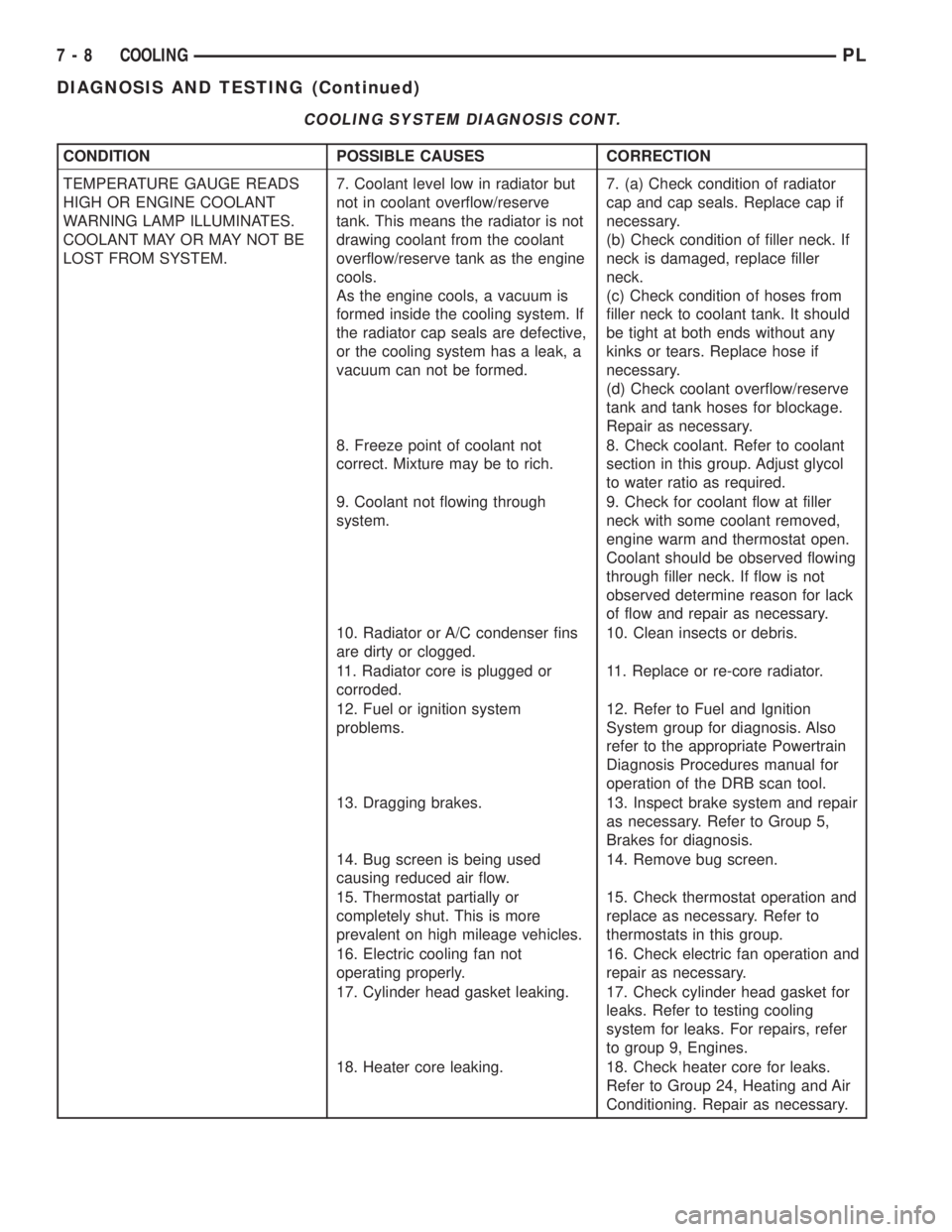
COOLING SYSTEM DIAGNOSIS CONT.
CONDITION POSSIBLE CAUSES CORRECTION
TEMPERATURE GAUGE READS
HIGH OR ENGINE COOLANT
WARNING LAMP ILLUMINATES.
COOLANT MAY OR MAY NOT BE
LOST FROM SYSTEM.7. Coolant level low in radiator but
not in coolant overflow/reserve
tank. This means the radiator is not
drawing coolant from the coolant
overflow/reserve tank as the engine
cools.
As the engine cools, a vacuum is
formed inside the cooling system. If
the radiator cap seals are defective,
or the cooling system has a leak, a
vacuum can not be formed.7. (a) Check condition of radiator
cap and cap seals. Replace cap if
necessary.
(b) Check condition of filler neck. If
neck is damaged, replace filler
neck.
(c) Check condition of hoses from
filler neck to coolant tank. It should
be tight at both ends without any
kinks or tears. Replace hose if
necessary.
(d) Check coolant overflow/reserve
tank and tank hoses for blockage.
Repair as necessary.
8. Freeze point of coolant not
correct. Mixture may be to rich.8. Check coolant. Refer to coolant
section in this group. Adjust glycol
to water ratio as required.
9. Coolant not flowing through
system.9. Check for coolant flow at filler
neck with some coolant removed,
engine warm and thermostat open.
Coolant should be observed flowing
through filler neck. If flow is not
observed determine reason for lack
of flow and repair as necessary.
10. Radiator or A/C condenser fins
are dirty or clogged.10. Clean insects or debris.
11. Radiator core is plugged or
corroded.11. Replace or re-core radiator.
12. Fuel or ignition system
problems.12. Refer to Fuel and Ignition
System group for diagnosis. Also
refer to the appropriate Powertrain
Diagnosis Procedures manual for
operation of the DRB scan tool.
13. Dragging brakes. 13. Inspect brake system and repair
as necessary. Refer to Group 5,
Brakes for diagnosis.
14. Bug screen is being used
causing reduced air flow.14. Remove bug screen.
15. Thermostat partially or
completely shut. This is more
prevalent on high mileage vehicles.15. Check thermostat operation and
replace as necessary. Refer to
thermostats in this group.
16. Electric cooling fan not
operating properly.16. Check electric fan operation and
repair as necessary.
17. Cylinder head gasket leaking. 17. Check cylinder head gasket for
leaks. Refer to testing cooling
system for leaks. For repairs, refer
to group 9, Engines.
18. Heater core leaking. 18. Check heater core for leaks.
Refer to Group 24, Heating and Air
Conditioning. Repair as necessary.
7 - 8 COOLINGPL
DIAGNOSIS AND TESTING (Continued)
Page 718 of 1200

(2) Remove negative battery cable.
(3) Place a shop towel around the spark plugs
when removing them from the engine. This will catch
any fluid that may possibly be in the cylinder under
pressure.
(4) With all spark plugs removed, rotate engine
crankshaft using a breaker bar and socket.
(5) Identify the fluid in the cylinder(s) (i.e., cool-
ant, fuel, oil or other).
(6) Make sure all fluid has been removed from the
cylinders. Inspect engine for damage (i.e., Connecting
Rods, Pistons, Valves etc.)
(7) Repair engine or components as necessary to
prevent this problem from occurring again.
CAUTION: Squirt approximately 1 teaspoon of oil
into cylinders, rotate engine to lubricate the cylin-
der walls to prevent damage on restart.
(8) Install new spark plugs.
(9) Drain engine oil and remove oil filter.
(10) Fill engine with specified amount of approved
oil and install new oil filter.
(11) Connect negative battery cable.
(12) Start engine and check for any leaks.
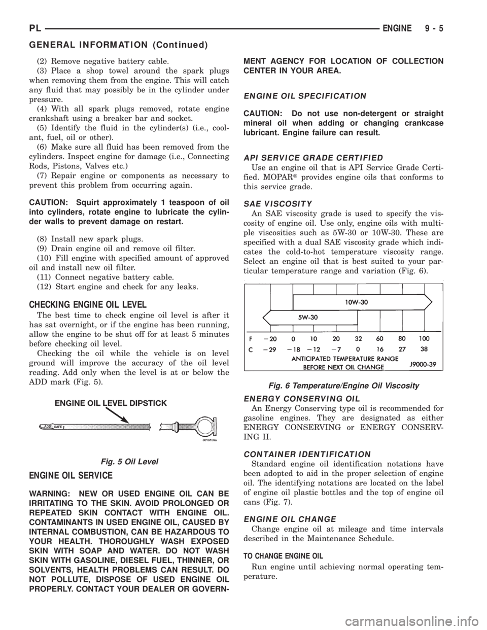
CHECKING ENGINE OIL LEVEL
The best time to check engine oil level is after it
has sat overnight, or if the engine has been running,
allow the engine to be shut off for at least 5 minutes
before checking oil level.
Checking the oil while the vehicle is on level
ground will improve the accuracy of the oil level
reading. Add only when the level is at or below the
ADD mark (Fig. 5).
ENGINE OIL SERVICE
WARNING: NEW OR USED ENGINE OIL CAN BE
IRRITATING TO THE SKIN. AVOID PROLONGED OR
REPEATED SKIN CONTACT WITH ENGINE OIL.
CONTAMINANTS IN USED ENGINE OIL, CAUSED BY
INTERNAL COMBUSTION, CAN BE HAZARDOUS TO
YOUR HEALTH. THOROUGHLY WASH EXPOSED
SKIN WITH SOAP AND WATER. DO NOT WASH
SKIN WITH GASOLINE, DIESEL FUEL, THINNER, OR
SOLVENTS, HEALTH PROBLEMS CAN RESULT. DO
NOT POLLUTE, DISPOSE OF USED ENGINE OIL
PROPERLY. CONTACT YOUR DEALER OR GOVERN-MENT AGENCY FOR LOCATION OF COLLECTION
CENTER IN YOUR AREA.
ENGINE OIL SPECIFICATION
CAUTION: Do not use non-detergent or straight
mineral oil when adding or changing crankcase
lubricant. Engine failure can result.
API SERVICE GRADE CERTIFIED
Use an engine oil that is API Service Grade Certi-
fied. MOPARtprovides engine oils that conforms to
this service grade.
SAE VISCOSITY
An SAE viscosity grade is used to specify the vis-
cosity of engine oil. Use only, engine oils with multi-
ple viscosities such as 5W-30 or 10W-30. These are
specified with a dual SAE viscosity grade which indi-
cates the cold-to-hot temperature viscosity range.
Select an engine oil that is best suited to your par-
ticular temperature range and variation (Fig. 6).
ENERGY CONSERVING OIL
An Energy Conserving type oil is recommended for
gasoline engines. They are designated as either
ENERGY CONSERVING or ENERGY CONSERV-
ING II.
CONTAINER IDENTIFICATION
Standard engine oil identification notations have
been adopted to aid in the proper selection of engine
oil. The identifying notations are located on the label
of engine oil plastic bottles and the top of engine oil
cans (Fig. 7).
ENGINE OIL CHANGE
Change engine oil at mileage and time intervals
described in the Maintenance Schedule.
TO CHANGE ENGINE OIL
Run engine until achieving normal operating tem-
perature.
Fig. 5 Oil Level
Fig. 6 Temperature/Engine Oil Viscosity
PLENGINE 9 - 5
GENERAL INFORMATION (Continued)
Page 842 of 1200

FUEL SYSTEM
CONTENTS
page page
FUEL DELIVERY SYSTEM................... 3
FUEL INJECTION SYSTEM................. 20GENERAL INFORMATION................... 1
GENERAL INFORMATION
INDEX
page page
GENERAL INFORMATION
FUEL REQUIREMENTS.................... 1
GASOLINE/OXYGENATE BLENDS............ 1INTRODUCTION......................... 1
PCM REPLACEMENT..................... 1
GENERAL INFORMATION
INTRODUCTION
Throughout this group, references may be made to
a particular vehicle by letter or number designation.
A chart showing the breakdown of these designations
is included in the Introduction Section at the front of
this service manual.
The Evaporation Control System, is also considered
part of the fuel system. The system reduces the emis-
sion of fuel vapor into the atmosphere.
The description and function of the Evaporation
Control System is found in Group 25 of this manual.
PCM REPLACEMENT
USE THE DRB SCAN TOOL TO REPROGRAM
THE NEW PCM WITH THE VEHICLES ORIGI-
NAL IDENTIFICATION NUMBER (VIN) AND
THE VEHICLES ORIGINAL MILEAGE. IF THIS
STEP IS NOT DONE A DIAGNOSTIC TROUBLE
CODE (DTC) MAY BE SET.
FUEL REQUIREMENTS
Your vehicle was designed to meet all emission reg-
ulations and provide excellent fuel economy when
using high quality unleaded gasoline.
Use unleaded gasolines having a minimum posted
octane of 87.
If your vehicle develops occasional light spark
knock (ping) at low engine speeds this is not harm-
ful. However; continued heavy knock at high speeds
can cause damage and should be reported to yourdealer immediately. Engine damage as a result of
heavy knock operation may not be covered by the
new vehicle warranty.
In addition to using unleaded gasoline with the
proper octane rating, those that contain detergents,
corrosion and stability additives are recommended.
Using gasolines that have these additives will help
improve fuel economy, reduce emissions, and main-
tain vehicle performance.
Poor quality gasoline can cause problems such as
hard starting, stalling, and stumble. If you experi-
ence these problems, try another brand of gasoline
before considering service for the vehicle.
GASOLINE/OXYGENATE BLENDS
Some fuel suppliers blend unleaded gasoline with
materials that contain oxygen such as alcohol, MTBE
(Methyl Tertiary Butyl Ether) and ETBE (Ethyl Ter-
tiary Butyl Ether). Oxygenates are required in some
areas of the country during winter months to reduce
carbon monoxide emissions. The type and amount of
oxygenate used in the blend is important.
The following are generally used in gasoline
blends:
Ethanol- (Ethyl or Grain Alcohol) properly
blended, is used as a mixture of 10 percent ethanol
and 90 percent gasoline. Gasoline blended with etha-
nol may be used in your vehicle.
MTBE/ETBE- Gasoline and MTBE (Methyl Ter-
tiary Butyl Ether) blends are a mixture of unleaded
gasoline and up to 15 percent MTBE. Gasoline and
ETBE (Ethyl Tertiary Butyl Ether) are blends of gas-
PLFUEL SYSTEM 14 - 1
Page 864 of 1200

below the minimum acceptable percentage, the PCM
stores a diagnostic trouble code in memory.
During certain idle conditions, the PCM may enter
a variable idle speed strategy. During variable idle
speed strategy the PCM adjusts engine speed based
on the following inputs.
²A/C sense
²Battery voltage
²Battery temperature
²Engine coolant temperature
²Engine run time
²Power steering pressure switch
²Vehicle mileage
ACCELERATION MODE
This is a CLOSED LOOP mode. The PCM recog-
nizes an abrupt increase in Throttle Position sensor
output voltage or MAP sensor output voltage as a
demand for increased engine output and vehicle
acceleration. The PCM increases injector pulse width
in response to increased fuel demand.
DECELERATION MODE
This is a CLOSED LOOP mode. During decelera-
tion the following inputs are received by the PCM:
²A/C pressure transducer
²A/C sense
²Battery voltage
²Intake air temperature
²Engine coolant temperature
²Crankshaft position (engine speed)
²Exhaust gas oxygen content (upstream heated
oxygen sensor)
²Knock sensor
²Manifold absolute pressure
²Power steering pressure switch
²Throttle position
²IAC motor control changes in respones to MAP
sensor feedback
The PCM may receive a closed throttle input from
the Throttle Position Sensor (TPS) when it senses an
abrupt decrease in manifold pressure. This indicates
a hard deceleration. In response, the PCM may
momentarily turn off the injectors. This helps
improve fuel economy, emissions and engine braking.
If decel fuel shutoff is detected, downstream oxy-
gen sensor diagnostics is performed.
WIDE-OPEN-THROTTLE MODE
This is an OPEN LOOP mode. During wide-open-
throttle operation, the following inputs are received
by the PCM:
²Intake air temperature
²Engine coolant temperature
²Engine speed
²Knock sensor
²Manifold absolute pressure²Throttle position
When the PCM senses a wide-open-throttle condi-
tion through the Throttle Position Sensor (TPS) it de-
energizes the A/C compressor clutch relay. This
disables the air conditioning system.
The PCM does not monitor the heated oxygen sen-
sor inputs during wide-open-throttle operation except
for downstream heated oxygen sensor and both
shorted diagnostics. The PCM adjusts injector pulse
width to supply a predetermined amount of addi-
tional fuel.
IGNITION SWITCH OFF MODE
When the operator turns the ignition switch to the
OFF position, the following occurs:
²All outputs are turned off, unless 02 Heater
Monitor test is being run. Refer to Group 25,
On-Board Diagnostics.
²No inputs are monitored except for the heated
oxygen sensors. The PCM monitors the heating ele-
ments in the oxygen sensors and then shuts down.
DESCRIPTION AND OPERATION
SYSTEM DIAGNOSIS
The PCM can test many of its own input and out-
put circuits. If the PCM senses a fault in a major
system, the PCM stores a Diagnostic Trouble Code
(DTC) in memory.
For DTC information, refer to Group 25, Emission
Control Systems. See On-Board Diagnostics.
POWER DISTRIBUTION CENTER
The power distribution center (PDC) is located next
to the battery (Fig. 1). The PDC contains the starter
relay, radiator fan relay, A/C compressor clutch relay,
auto shutdown relay, fuel pump relay and several
fuses.
Fig. 1 Power Distribution Center (PDC)
PLFUEL SYSTEM 14 - 23
GENERAL INFORMATION (Continued)
Page 1000 of 1200

to 3mm (1/8 in.) below the ADD mark on the dip-
stick.
(9) Recheck the fluid level after the transaxle is at
normal operating temperature. The level should be in
the HOT range. Drive the vehicle a minimum of 10
miles.
(10) Raise the vehicle on the hoist.
(11) Check for leaks around the transaxle oil pan
sealing surfaces.
(12) Recheck the fluid level. The level should be in
the HOT range.
SEVERE USAGE SERVICE
If the vehicle exhibits any of the following symp-
toms, it is recommended that the transaxle oil and
filter be replaced.
²Transaxle oil discolored
²Transaxle oil has high mileage
²Oil feels grimy when rubbed between fingertips
²Poor shift quality
²Delayed gear engagement
²Vehicle shudder between shifts
TRANSAXLE OIL AND FILTER REPLACEMENT
This procedure involves changing the transaxle
fluid and filter, driving the vehicle for 10 miles and
changing the transaxle fluid a second time.
(1) Bring the vehicle up to normal operating tem-
perature. Drive the vehicle a minimum of 10 miles.
(2) Raise the vehicle on the hoist.
(3) Loosen the transaxle oil pan and drain the
fluid into a suitable container.
(4) Remove the pan and clean all sealant from the
pan and transaxle mating surfaces. Clean the mag-
net and the inside of the pan.
(5) Separate the filter and O-ring from the valve
body. Inspect the O-ring for cuts or improper instal-
lation. This could lead to delayed garage shifts.
(6) Install a new filter. Replace the O-ring as nec-
essary.
(7) Apply a 1/8 inch bead of Mopar RTV Sealant to
the mounting flange of the transaxle oil pan. Apply
RTV Sealant to the underside of the attaching bolts.
Attach the oil pan to the transaxle. Tighten the bolts
to 19 N²m (165 in. lbs.).
(8) Lower the vehicle and add 4 Quarts of Mopar
ATF Plus 3 Type 7176 transaxle fluid.
(9) Start the engine and allow it to idle for a min-
imum of one minute. With the parking brake applied,
press your foot on the service brake and cycle the
transaxle from park to all gear positions ending in
neutral or park.
(10) Check the transaxle fluid level and add an
appropriate amount to bring the transaxle fluid level
to 3mm (1/8 in.) below the ADD mark on the dip-
stick.(11) Recheck the fluid level after the transaxle is
at normal operating temperature. The level should be
in the HOT range. Drive the vehicle a minimum of
10 miles.
(12) Raise the vehicle on the hoist.
(13) Remove the pan and clean all sealant from
the pan and transaxle mating surfaces. Clean the
magnet and the inside of the pan.
(14) Separate the filter from the valve body to
allow additional fluid to drain from the transaxle.
Inspect the filter O-ring for any damage and replace
as necessary.
(15) After the transaxle has stopped draining,
reinstall the filter and O-ring.
(16) Apply a 1/8 inch bead of Mopar RTV Sealant
to the mounting flange of the transaxle oil pan.
Apply RTV Sealant to the underside of the attaching
bolts. Attach the oil pan to the transaxle. Tighten the
bolts to 19 N²m (165 in. lbs.).
(17) Lower the vehicle and add 4 Quarts of Mopar
ATF Plus 3 Type 7176 transaxle fluid.
(18) Start the engine and allow it to idle for a min-
imum of one minute. With the parking brake applied,
press your foot on the service brake and cycle the
transaxle from park to all gear positions ending in
neutral or park.
(19) Check the transaxle fluid level and add an
appropriate amount to bring the transaxle fluid level
to 3mm (1/8 in.) below the ADD mark on the dip-
stick.
(20) Recheck the fluid level after the transaxle is
at normal operating temperature. The level should be
in the HOT range.
FLUID DRAIN AND REFILL
(1) Raise vehicle on a hoist (See Group 0, Lubrica-
tion). Place a drain container, with a large opening,
under transaxle oil pan.
(2) Loosen pan bolts and tap the pan at one corner
to break it loose allowing fluid to drain, then remove
the oil pan.
(3) Install a new filter and gasket on bottom of the
valve body and tighten retaining screws to 5 N´m (40
inch-pounds).
(4) Clean the oil pan and magnet. Reinstall pan
using new sealant. Tighten oil pan bolts to 19 N´m
(165 in. lbs.).
(5) Pour four quarts of Mopar ATF PLUS 3 (Auto-
matic Transmission Fluid) type 7176 into the tran-
saxle filler tube.
(6) Start engine and allow to idle for at least one
minute. Then, with parking and service brakes
applied, move selector lever momentarily to each
position, ending in the PARK or NEUTRAL position.
(7) Add sufficient fluid to bring level to 1/8 inch
below the ADD mark.
PLTRANSAXLE 21 - 57
SERVICE PROCEDURES (Continued)