1999 DODGE NEON fuel cap release
[x] Cancel search: fuel cap releasePage 207 of 1200

WATER PUMP DIAGNOSIS
A quick flow test to tell whether or not the pump is
working is to see if the heater warms properly. A
defective pump will not be able to circulate heated
coolant through the long heater hose.
Another flow test to help determine pump opera-
tion.
WARNING: DO NOT remove radiator cap if the cool-
ing system is hot or under pressure.
(1) Remove radiator cap.
(2) Remove a small amount of coolant from the
system, start the engine and warm up until thermo-
stat opens. With the thermostat open and coolant
level low you will see if the water pump is pumping
coolant through the system.
COOLING SYSTEM FLOW CHECK
To determine whether coolant is flowing through
the cooling system, use the following procedures:
(1) If engine is cold, idle engine until normal oper-
ating temperature is reached. Then feel the upper
radiator hose. If it is hot, coolant is circulating.
WARNING: DO NOT REMOVE THE COOLING SYS-
TEM PRESSURE CAP WITH THE SYSTEM HOT AND
UNDER PRESSURE BECAUSE SERIOUS BURNS
FROM COOLANT CAN OCCUR.
(2) Remove pressure cap when engine is cold,
remove small amount of coolant Idle engine until
thermostat opens, you should observe coolant flow
while looking down the filler neck. Once flow is
detected install the pressure cap.
RADIATOR FAN CONTROL
Fan control is accomplished two ways. The fan
always runs when the air conditioning compressor
clutch is engaged. In addition to this control, the fan
is turned on by the temperature of the coolant which
is sensed by the coolant temperature sensor which
sends the message to the Powertrain Control Module
(PCM). The (PCM) turns on the fan through the
Solid State Fan Relay. The Solid State Fan Relay is
located on the left front inner frame just behind the
radiator. See Wiring Diagrams Manual for circuity
and diagnostics provided.
Switching through the (PCM) provides fan control
for the following conditions.
²The fan will not run during cranking until the
engine starts no matter what the coolant tempera-
ture is.
²Fan will run when the air conditioning clutch is
engaged and low pressure cutout switch is closed.
²Fan will run at vehicle speeds above about 40
mph only if coolant temperature reaches 110ÉC(230ÉF). It will turn off when the temperature drops
to 104ÉC (220ÉF). At speeds below 40 mph the fan
switches on at 102ÉC (215ÉF) and off at 93ÉC (200ÉF).
Refer to Radiator Fan Control Module Group 14,
Fuel Injection for more information.
ELECTRIC FAN MOTOR TEST
Refer to Powertrain Diagnostic Manual for procedure.
TESTING COOLING SYSTEM FOR LEAKS
The system should be full. With the engine not
running, wipe the filler neck sealing seat clean.
Attach a radiator pressure tester to the filler neck,
as shown in (Fig. 9) and apply 104 kPa (15 psi) pres-
sure. If the pressure drops more than 2 psi in 2 min-
utes, inspect the system for external leaks.
Move all hoses at the radiator and heater while
system is pressurize at 15 psi, since some leaks occur
due to engine rock while driving.
If there are no external leaks after the gauge dial
shows a drop in pressure, detach the tester. Start the
engine, and run the engine to normal operating tem-
perature in order to open the thermostat and allow
the coolant to expand. Reattach the tester. If the nee-
dle on the dial fluctuates it indicates a combustion
leak, usually a head gasket leak.
WARNING: WITH THE PRESSURE TESTER IN
PLACE PRESSURE BUILDS UP QUICKLY. ANY
EXCESSIVE PRESSURE BUILD-UP DUE TO CON-
TINUOUS ENGINE OPERATION MUST BE
RELEASED TO A SAFE PRESSURE POINT. NEVER
PERMIT PRESSURE TO EXCEED 138 kPa (20 psi).
If the needle on the dial does not fluctuate, race
the engine a few times. If an abnormal amount of
coolant or steam is emitted from the tail pipe, it may
indicate a faulty head gasket, cracked engine block,
or cracked cylinder head.
Fig. 9 Pressure Testing Cooling SystemÐTypical
7 - 14 COOLINGPL
DIAGNOSIS AND TESTING (Continued)
Page 821 of 1200
NOTE: When replacement is required on any com-
ponent of the exhaust system, you must use origi-
nal equipment parts (or their equivalent).
INSTALLATION
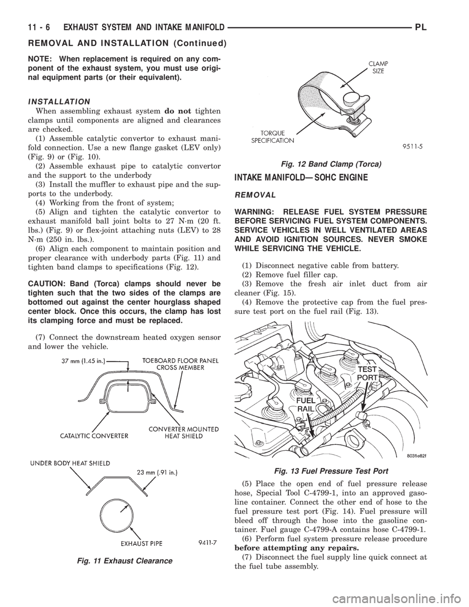
When assembling exhaust systemdo nottighten
clamps until components are aligned and clearances
are checked.
(1) Assemble catalytic convertor to exhaust mani-
fold connection. Use a new flange gasket (LEV only)
(Fig. 9) or (Fig. 10).
(2) Assemble exhaust pipe to catalytic convertor
and the support to the underbody
(3) Install the muffler to exhaust pipe and the sup-
ports to the underbody.
(4) Working from the front of system;
(5) Align and tighten the catalytic convertor to
exhaust manifold ball joint bolts to 27 N´m (20 ft.
lbs.) (Fig. 9) or flex-joint attaching nuts (LEV) to 28
N´m (250 in. lbs.).
(6) Align each component to maintain position and
proper clearance with underbody parts (Fig. 11) and
tighten band clamps to specifications (Fig. 12).
CAUTION: Band (Torca) clamps should never be
tighten such that the two sides of the clamps are
bottomed out against the center hourglass shaped
center block. Once this occurs, the clamp has lost
its clamping force and must be replaced.
(7) Connect the downstream heated oxygen sensor
and lower the vehicle.
INTAKE MANIFOLDÐSOHC ENGINE
REMOVAL
WARNING: RELEASE FUEL SYSTEM PRESSURE
BEFORE SERVICING FUEL SYSTEM COMPONENTS.
SERVICE VEHICLES IN WELL VENTILATED AREAS
AND AVOID IGNITION SOURCES. NEVER SMOKE
WHILE SERVICING THE VEHICLE.
(1) Disconnect negative cable from battery.
(2) Remove fuel filler cap.
(3) Remove the fresh air inlet duct from air
cleaner (Fig. 15).
(4) Remove the protective cap from the fuel pres-
sure test port on the fuel rail (Fig. 13).
(5) Place the open end of fuel pressure release
hose, Special Tool C-4799-1, into an approved gaso-
line container. Connect the other end of hose to the
fuel pressure test port (Fig. 14). Fuel pressure will
bleed off through the hose into the gasoline con-
tainer. Fuel gauge C-4799-A contains hose C-4799-1.
(6) Perform fuel system pressure release procedure
before attempting any repairs.
(7) Disconnect the fuel supply line quick connect at
the fuel tube assembly.
Fig. 11 Exhaust Clearance
Fig. 12 Band Clamp (Torca)
Fig. 13 Fuel Pressure Test Port
11 - 6 EXHAUST SYSTEM AND INTAKE MANIFOLDPL
REMOVAL AND INSTALLATION (Continued)
Page 824 of 1200

INTAKE MANIFOLDÐDOHC ENGINE
REMOVAL
WARNING: RELEASE FUEL SYSTEM PRESSURE
BEFORE SERVICING FUEL SYSTEM COMPONENTS.
SERVICE VEHICLES IN WELL VENTILATED AREAS
AND AVOID IGNITION SOURCES. NEVER SMOKE
WHILE SERVICING THE VEHICLE.
(1) Disconnect negative cable from battery.
(2) Remove fuel filler cap.
(3) Loosen wing nut on intake and remove fresh
air inlet duct (Fig. 23).
(4) Remove the protective cap from the fuel pres-
sure test port on the fuel rail (Fig. 21).
(5) Place the open end of fuel pressure release
hose, Special Tool C-4799-1, into an approved gaso-
line container. Connect the other end of hose to the
fuel pressure test port (Fig. 22). Fuel pressure will
bleed off through the hose into the gasoline con-
tainer. Fuel gauge C-4799-A contains hose C-4799-1.
(6) Disconnect the fuel supply line quick-connect at
the fuel tube assembly.
(7) Remove clean air inlet duct.WARNING: WRAP SHOP TOWELS AROUND HOSE
TO CATCH ANY GASOLINE SPILLAGE.
(8) Disconnect the coolant temperature sensor
(Fig. 24).
(9) Disconnect heater hose from intake manifold.
(10) Disconnect heater tube from bottom of intake
manifold.
(11) Disconnect upper radiator hose and coolant
recovery hose.
(12) Remove fuel rail assembly attaching screws
and remove fuel rail assembly from engine. Cover
injector holes with suitable covering.
CAUTION: Do not set fuel injectors on their tips,
damage may occur to the injectors
Fig. 21 Fuel Pressure Test PortÐTypical
Fig. 22 Releasing Fuel PressureÐTypical
Fig. 23 Fresh Air Inlet Duct
Fig. 24 Engine Coolant Temperature Sensor
PLEXHAUST SYSTEM AND INTAKE MANIFOLD 11 - 9
REMOVAL AND INSTALLATION (Continued)
Page 844 of 1200
FUEL DELIVERY SYSTEM
INDEX
page page
DESCRIPTION AND OPERATION
ELECTRIC FUEL PUMP.................... 4
FUEL DELIVERY SYSTEM.................. 3
FUEL FILTER/FUEL PRESSURE REGULATOR . . . 4
FUEL GAUGE SENDING UNIT............... 4
FUEL INJECTORS........................ 5
FUEL PUMP MODULE..................... 3
FUEL RAIL.............................. 4
FUEL TANK............................. 4
PRESSURE-VACUUM FILLER CAP........... 5
QUICK-CONNECT FITTINGS................ 5
ROLLOVER VALVES...................... 5
DIAGNOSIS AND TESTING
FUEL INJECTORS........................ 8
FUEL LEVEL SENSOR..................... 6
FUEL PUMP PRESSURE TEST.............. 6
SERVICE PROCEDURES
DRAINING FUEL TANK.................... 10
FUEL SYSTEM PRESSURE RELEASE
PROCEDURE......................... 10HOSES AND CLAMPS.................... 10
QUICK-CONNECT FITTINGS............... 11
REMOVAL AND INSTALLATION
ACCELERATOR PEDAL................... 17
AUTOMATIC SHUTDOWN RELAY........... 11
FUEL FILLER NECK...................... 16
FUEL FILLER TUBE ROLLOVER VALVE....... 16
FUEL FILTER / PRESSURE REGULATOR..... 12
FUEL INJECTORS....................... 14
FUEL LEVEL SENSOR.................... 13
FUEL PUMP INLET STRAINER............. 13
FUEL PUMP MODULE.................... 11
FUEL PUMP RELAY...................... 11
FUEL TANK............................ 15
THROTTLE CABLEÐAUTOMATIC
TRANSMISSION....................... 18
THROTTLE CABLEÐMANUAL TRANSMISSION . 17
SPECIFICATIONS
FUEL TANK CAPACITY................... 19
TORQUE.............................. 19
DESCRIPTION AND OPERATION
FUEL DELIVERY SYSTEM
The fuel delivery system consists of: the electric
fuel pump, fuel filter/fuel pressure regulator, fuel
tubes/lines/hoses, fuel rail, fuel injectors, fuel tank,
accelerator pedal and throttle cable.
A fuel return system is used on all models (all
engines). Fuel is returned through the fuel pump
module and back into the fuel tank through the fuel
filter/fuel pressure regulator. A separate fuel return
line from the engine to the tank is no longer used
with any engine.
The fuel tank assembly consists of: the fuel tank,
filler tube, fuel gauge sending unit/electric fuel pump
module, a pressure relief/rollover valve and a pres-
sure-vacuum filler cap.
Also to be considered part of the fuel system is the
evaporation control system. This is designed to
reduce the emission of fuel vapors into the atmo-
sphere. The description and function of the Evapora-
tive Control System is found in Group 25, Emission
Control Systems.
FUEL PUMP MODULE
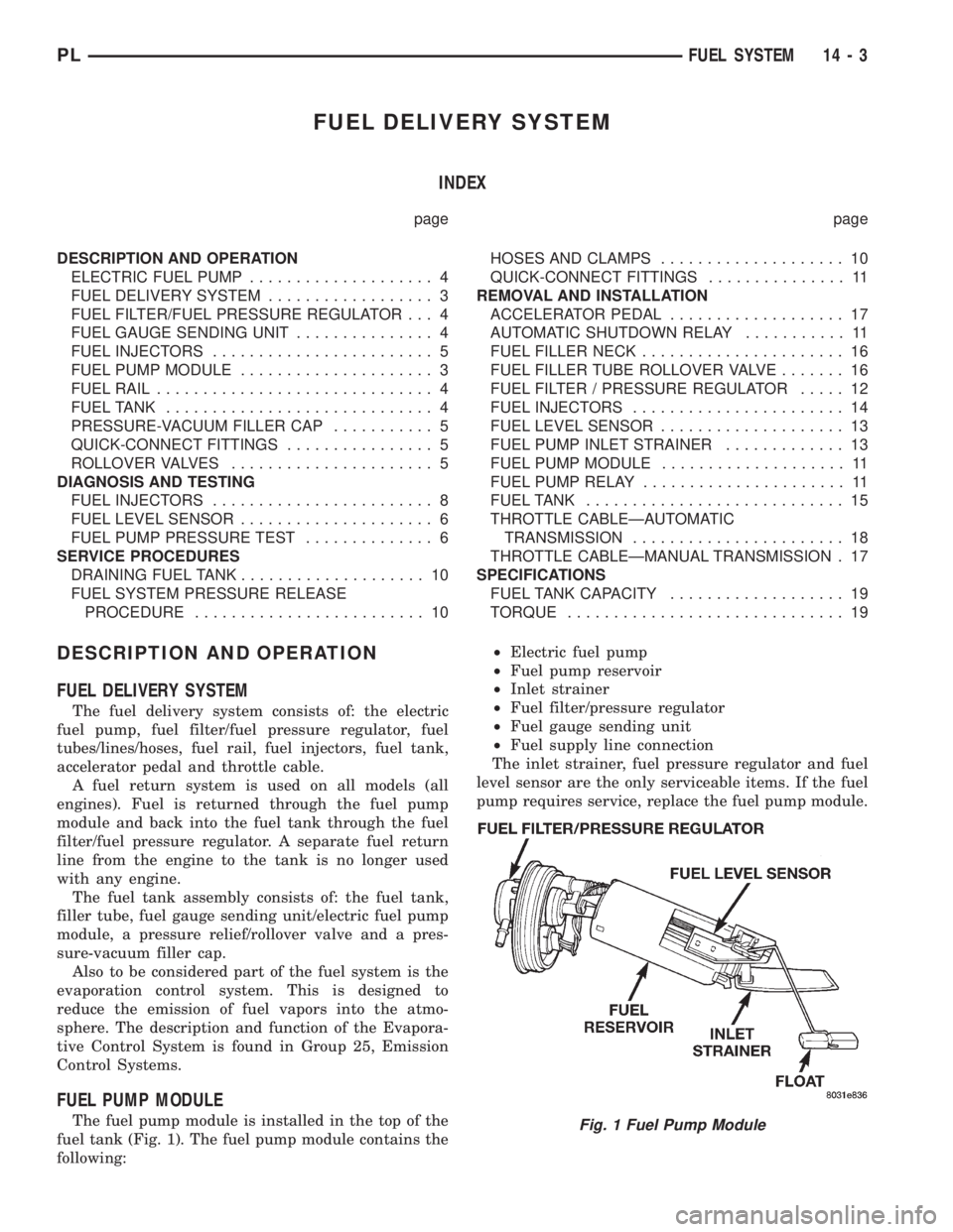
The fuel pump module is installed in the top of the
fuel tank (Fig. 1). The fuel pump module contains the
following:²Electric fuel pump
²Fuel pump reservoir
²Inlet strainer
²Fuel filter/pressure regulator
²Fuel gauge sending unit
²Fuel supply line connection
The inlet strainer, fuel pressure regulator and fuel
level sensor are the only serviceable items. If the fuel
pump requires service, replace the fuel pump module.Fig. 1 Fuel Pump Module
PLFUEL SYSTEM 14 - 3
Page 846 of 1200
FUEL INJECTORS
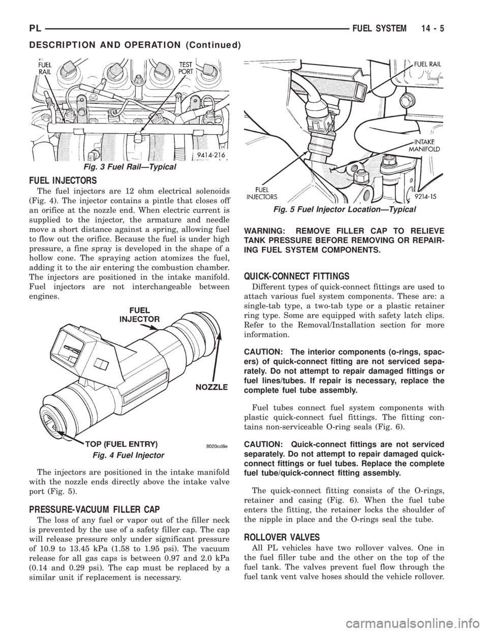
The fuel injectors are 12 ohm electrical solenoids
(Fig. 4). The injector contains a pintle that closes off
an orifice at the nozzle end. When electric current is
supplied to the injector, the armature and needle
move a short distance against a spring, allowing fuel
to flow out the orifice. Because the fuel is under high
pressure, a fine spray is developed in the shape of a
hollow cone. The spraying action atomizes the fuel,
adding it to the air entering the combustion chamber.
The injectors are positioned in the intake manifold.
Fuel injectors are not interchangeable between
engines.
The injectors are positioned in the intake manifold
with the nozzle ends directly above the intake valve
port (Fig. 5).
PRESSURE-VACUUM FILLER CAP
The loss of any fuel or vapor out of the filler neck
is prevented by the use of a safety filler cap. The cap
will release pressure only under significant pressure
of 10.9 to 13.45 kPa (1.58 to 1.95 psi). The vacuum
release for all gas caps is between 0.97 and 2.0 kPa
(0.14 and 0.29 psi). The cap must be replaced by a
similar unit if replacement is necessary.WARNING: REMOVE FILLER CAP TO RELIEVE
TANK PRESSURE BEFORE REMOVING OR REPAIR-
ING FUEL SYSTEM COMPONENTS.
QUICK-CONNECT FITTINGS
Different types of quick-connect fittings are used to
attach various fuel system components. These are: a
single-tab type, a two-tab type or a plastic retainer
ring type. Some are equipped with safety latch clips.
Refer to the Removal/Installation section for more
information.
CAUTION: The interior components (o-rings, spac-
ers) of quick-connect fitting are not serviced sepa-
rately. Do not attempt to repair damaged fittings or
fuel lines/tubes. If repair is necessary, replace the
complete fuel tube assembly.
Fuel tubes connect fuel system components with
plastic quick-connect fuel fittings. The fitting con-
tains non-serviceable O-ring seals (Fig. 6).
CAUTION: Quick-connect fittings are not serviced
separately. Do not attempt to repair damaged quick-
connect fittings or fuel tubes. Replace the complete
fuel tube/quick-connect fitting assembly.
The quick-connect fitting consists of the O-rings,
retainer and casing (Fig. 6). When the fuel tube
enters the fitting, the retainer locks the shoulder of
the nipple in place and the O-rings seal the tube.
ROLLOVER VALVES
All PL vehicles have two rollover valves. One in
the fuel filler tube and the other on the top of the
fuel tank. The valves prevent fuel flow through the
fuel tank vent valve hoses should the vehicle rollover.
Fig. 3 Fuel RailÐTypical
Fig. 4 Fuel Injector
Fig. 5 Fuel Injector LocationÐTypical
PLFUEL SYSTEM 14 - 5
DESCRIPTION AND OPERATION (Continued)
Page 851 of 1200
SERVICE PROCEDURES
FUEL SYSTEM PRESSURE RELEASE PROCEDURE
WARNING: RELEASE FUEL SYSTEM PRESSURE
BEFORE SERVICING FUEL SYSTEM COMPONENTS.
SERVICE VEHICLES IN WELL VENTILATED AREAS
AND AVOID IGNITION SOURCES. NEVER SMOKE
WHILE SERVICING THE VEHICLE.
(1) Disconnect negative cable from battery.
(2) Remove fuel filler cap.
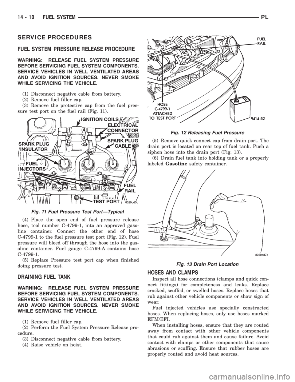
(3) Remove the protective cap from the fuel pres-
sure test port on the fuel rail (Fig. 11).
(4) Place the open end of fuel pressure release
hose, tool number C-4799-1, into an approved gaso-
line container. Connect the other end of hose
C-4799-1 to the fuel pressure test port (Fig. 12). Fuel
pressure will bleed off through the hose into the gas-
oline container. Fuel gauge C-4799-A contains hose
C-4799-1.
(5) Replace Pressure test port cap when finished
doing pressure test.
DRAINING FUEL TANK
WARNING: RELEASE FUEL SYSTEM PRESSURE
BEFORE SERVICING FUEL SYSTEM COMPONENTS.
SERVICE VEHICLES IN WELL VENTILATED AREAS
AND AVOID IGNITION SOURCES. NEVER SMOKE
WHILE SERVICING THE VEHICLE.
(1) Remove fuel filler cap.
(2) Perform the Fuel System Pressure Release pro-
cedure.
(3) Disconnect negative cable from battery.
(4) Raise vehicle on hoist.(5) Remove quick connect cap from drain port. The
drain port is located on rear top of fuel tank. Push a
siphon hose into the drain port (Fig. 13).
(6) Drain fuel tank into holding tank or a properly
labeledGasolinesafety container.
HOSES AND CLAMPS
Inspect all hose connections (clamps and quick con-
nect fittings) for completeness and leaks. Replace
cracked, scuffed, or swelled hoses. Replace hoses that
rub against other vehicle components or show sign of
wear.
Fuel injected vehicles use specially constructed
hoses. When replacing hoses, only use hoses marked
EFM/EFI.
When installing hoses, ensure that they are routed
away from contact with other vehicle components
that could rub against them and cause failure. Avoid
contact with clamps or other components that cause
abrasions or scuffing. Ensure that rubber hoses are
properly routed and avoid heat sources.
Fig. 11 Fuel Pressure Test PortÐTypical
Fig. 12 Releasing Fuel Pressure
Fig. 13 Drain Port Location
14 - 10 FUEL SYSTEMPL
Page 857 of 1200
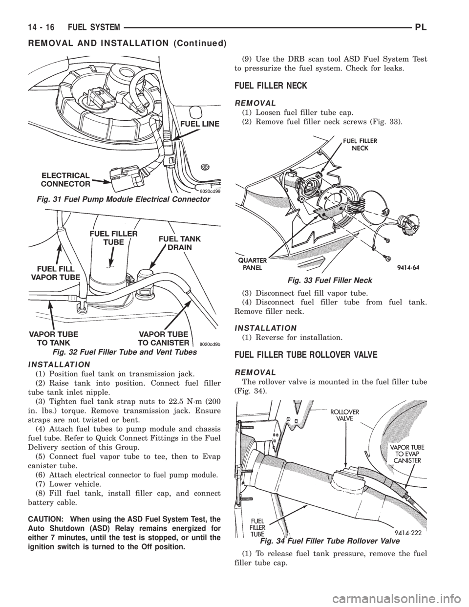
INSTALLATION
(1) Position fuel tank on transmission jack.
(2) Raise tank into position. Connect fuel filler
tube tank inlet nipple.
(3) Tighten fuel tank strap nuts to 22.5 N´m (200
in. lbs.) torque. Remove transmission jack. Ensure
straps are not twisted or bent.
(4) Attach fuel tubes to pump module and chassis
fuel tube. Refer to Quick Connect Fittings in the Fuel
Delivery section of this Group.
(5) Connect fuel vapor tube to tee, then to Evap
canister tube.
(6)
Attach electrical connector to fuel pump module.
(7) Lower vehicle.
(8) Fill fuel tank, install filler cap, and connect
battery cable.
CAUTION: When using the ASD Fuel System Test, the
Auto Shutdown (ASD) Relay remains energized for
either 7 minutes, until the test is stopped, or until the
ignition switch is turned to the Off position.
(9) Use the DRB scan tool ASD Fuel System Test
to pressurize the fuel system. Check for leaks.
FUEL FILLER NECK
REMOVAL
(1) Loosen fuel filler tube cap.
(2) Remove fuel filler neck screws (Fig. 33).
(3) Disconnect fuel fill vapor tube.
(4) Disconnect fuel filler tube from fuel tank.
Remove filler neck.
INSTALLATION
(1) Reverse for installation.
FUEL FILLER TUBE ROLLOVER VALVE
REMOVAL
The rollover valve is mounted in the fuel filler tube
(Fig. 34).
(1) To release fuel tank pressure, remove the fuel
filler tube cap.
Fig. 31 Fuel Pump Module Electrical Connector
Fig. 32 Fuel Filler Tube and Vent Tubes
Fig. 33 Fuel Filler Neck
Fig. 34 Fuel Filler Tube Rollover Valve
14 - 16 FUEL SYSTEMPL
REMOVAL AND INSTALLATION (Continued)