1999 DODGE NEON oil additives
[x] Cancel search: oil additivesPage 197 of 1200
DESCRIPTION AND OPERATION
ENGINE THERMOSTAT
The engine cooling thermostats are wax pellet
driven, reverse poppet choke type. They are designed
to provide the fastest warm up possible by prevent-
ing leakage through them and to guarantee a mini-
mum engine operating temperature of 88 to 93ÉC
(192 to 199ÉF). They also automatically reach wide
open so they do not restrict flow to the radiator as
temperature of the coolant rises in hot weather to
around 104ÉC (220ÉF). Above this temperature the
coolant temperature is controlled by the radiator, fan,
and ambient temperature, not the thermostat.
Its primary purpose is to maintain engine temper-
ature in a range that will provide satisfactory engine
performance and emission levels under all expected
driving conditions. It also provides hot water (cool-
ant) for heater performance. It does this by transfer-
ring heat from engine metal and automatic
transmission oil cooler (if equipped) to coolant, mov-
ing this heated coolant to the heater core and radia-
tor, and then transferring this heat to the ambient
air.
COOLANT PERFORMANCE
Performance is measurable. For heat transfer pure
water excels (Formula = 1 btu per minute for each
degree of temperature rise for each pound of water).
This formula is altered when necessary additives to
control boiling, freezing, and corrosion are added as
follows:
²Pure Water (1 btu) boils at 100ÉC (212ÉF) and
freezes at 0ÉC (32ÉF).
²100 Percent Glycol (.7 btu) can cause a hot
engine and detonation and will raise the freeze point
to 22ÉC (-8ÉF).
²50/50 Glycol and Water (.82 btu) is the recom-
mended combination that provides a freeze point of
-37ÉC(-35ÉF). The radiator, water pump, engine water
jacket, radiator pressure cap, thermostat, tempera-
ture gauge, sending unit and heater are all designed
for 50/50 glycol.
Where required, a 56 percent glycol and 44 percent
water mixture will provide a freeze point of -59ÉC
(-50ÉF).
CAUTION: Richer mixtures cannot be measured
with field equipment which can lead to problems
associated with 100 percent glycol.
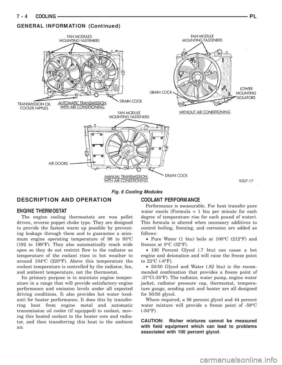
Fig. 6 Cooling Modules
7 - 4 COOLINGPL
GENERAL INFORMATION (Continued)
Page 198 of 1200
SELECTION AND ADDITIVES
The use of aluminum cylinder heads, intake mani-
folds DOHC, and water pumps requires special corro-
sion protection. MopartAntifreeze or the equivalent
is recommended for best engine cooling without cor-
rosion. When mixed only to a freeze point of -37ÉC
(-35ÉF) to -59ÉC (-50ÉF). If it looses color or becomes
contaminated, drain, flush, and replace with fresh
properly mixed solution.
COOLING SYSTEM PRESSURE CAP
The cooling system is equipped with a pressure cap
that releases built up pressure, maintaining a range
of 97-124 kPa (14-18 psi).
The cooling system will operate at higher than
atmospheric pressure. The higher pressure raises the
coolant boiling point thus, allowing increased radia-
tor cooling capacity.
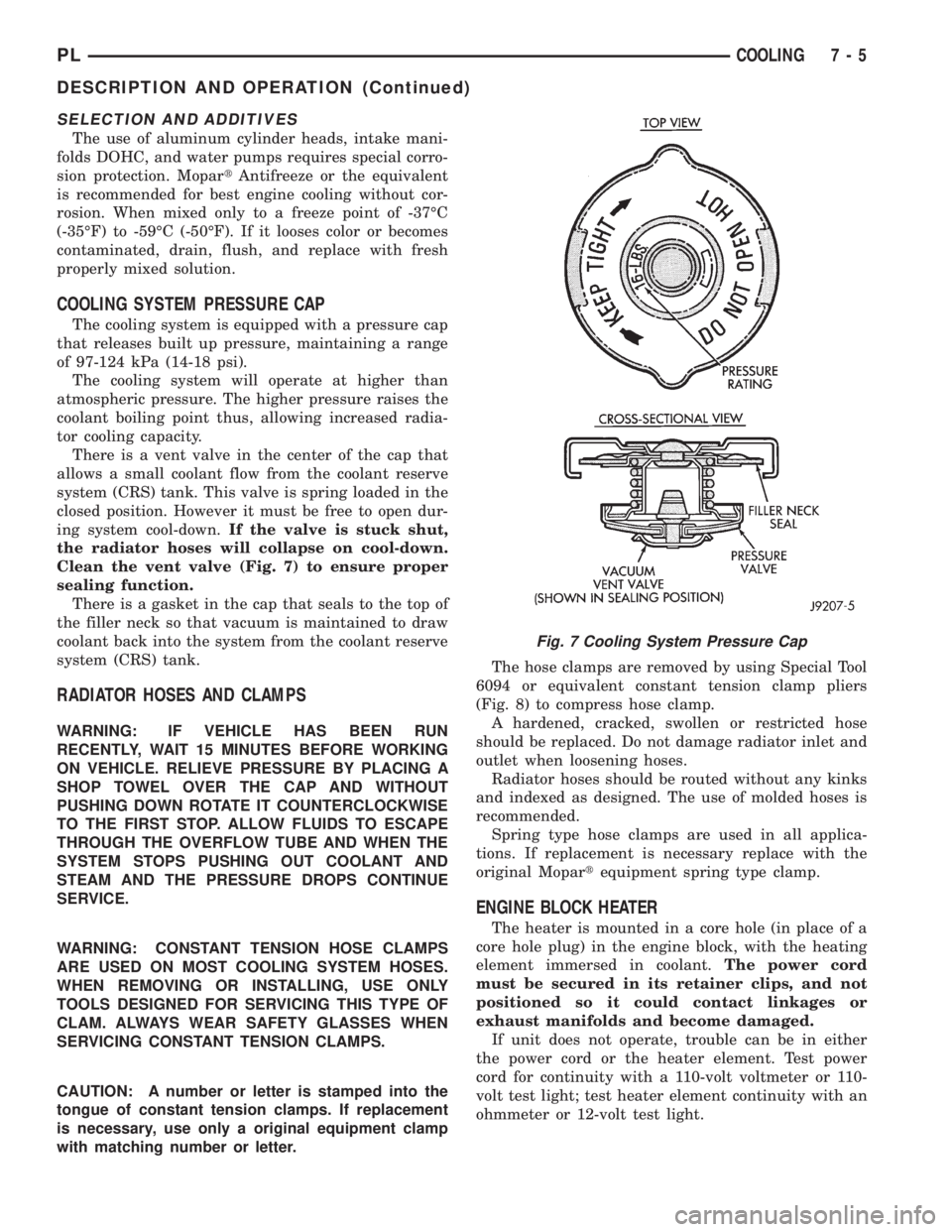
There is a vent valve in the center of the cap that
allows a small coolant flow from the coolant reserve
system (CRS) tank. This valve is spring loaded in the
closed position. However it must be free to open dur-
ing system cool-down.If the valve is stuck shut,
the radiator hoses will collapse on cool-down.
Clean the vent valve (Fig. 7) to ensure proper
sealing function.
There is a gasket in the cap that seals to the top of
the filler neck so that vacuum is maintained to draw
coolant back into the system from the coolant reserve
system (CRS) tank.
RADIATOR HOSES AND CLAMPS
WARNING: IF VEHICLE HAS BEEN RUN
RECENTLY, WAIT 15 MINUTES BEFORE WORKING
ON VEHICLE. RELIEVE PRESSURE BY PLACING A
SHOP TOWEL OVER THE CAP AND WITHOUT
PUSHING DOWN ROTATE IT COUNTERCLOCKWISE
TO THE FIRST STOP. ALLOW FLUIDS TO ESCAPE
THROUGH THE OVERFLOW TUBE AND WHEN THE
SYSTEM STOPS PUSHING OUT COOLANT AND
STEAM AND THE PRESSURE DROPS CONTINUE
SERVICE.
WARNING: CONSTANT TENSION HOSE CLAMPS
ARE USED ON MOST COOLING SYSTEM HOSES.
WHEN REMOVING OR INSTALLING, USE ONLY
TOOLS DESIGNED FOR SERVICING THIS TYPE OF
CLAM. ALWAYS WEAR SAFETY GLASSES WHEN
SERVICING CONSTANT TENSION CLAMPS.
CAUTION: A number or letter is stamped into the
tongue of constant tension clamps. If replacement
is necessary, use only a original equipment clamp
with matching number or letter.The hose clamps are removed by using Special Tool
6094 or equivalent constant tension clamp pliers
(Fig. 8) to compress hose clamp.
A hardened, cracked, swollen or restricted hose
should be replaced. Do not damage radiator inlet and
outlet when loosening hoses.
Radiator hoses should be routed without any kinks
and indexed as designed. The use of molded hoses is
recommended.
Spring type hose clamps are used in all applica-
tions. If replacement is necessary replace with the
original Mopartequipment spring type clamp.
ENGINE BLOCK HEATER
The heater is mounted in a core hole (in place of a
core hole plug) in the engine block, with the heating
element immersed in coolant.The power cord
must be secured in its retainer clips, and not
positioned so it could contact linkages or
exhaust manifolds and become damaged.
If unit does not operate, trouble can be in either
the power cord or the heater element. Test power
cord for continuity with a 110-volt voltmeter or 110-
volt test light; test heater element continuity with an
ohmmeter or 12-volt test light.
Fig. 7 Cooling System Pressure Cap
PLCOOLING 7 - 5
DESCRIPTION AND OPERATION (Continued)
Page 259 of 1200

Connect the DVM between the center and sensor
ground terminal. Refer to Group 8W - Wiring Dia-
grams for correct pinout.
With the ignition switch in the ON position, check
the output voltage at the center terminal wire of the
connector. Check the output voltage at idle and at
Wide-Open-Throttle (WOT). At idle, TPS output volt-
age should be approximately 0.38 volts to 1.2 volts.
At wide open throttle, TPS output voltage should be
approximately 3.1 volts to 4.4 volts. The output volt-
age should gradually increase as the throttle plate
moves slowly from idle to WOT.
Check for spread terminals at the sensor and PCM
connections before replacing the TPS.
SPARK PLUG CONDITION
NORMAL OPERATING CONDITIONS
The few deposits present will be probably light tan
or slightly gray in color with most grades of commer-
cial gasoline (Fig. 21). There will not be evidence of
electrode burning. Gap growth will not average more
than approximately 0.025 mm (.001 in) per 1600 km
(1000 miles) of operation for non platinum spark
plugs. Non-platnium spark plugs that have normal
wear can usually be cleaned, have the electrodes filed
and regapped, and then reinstalled.
CAUTION: Never attempt to file the electrodes or
use a wire brush for cleaning platinum spark plugs.
This would damage the platinum pads which would
shorten spark plug life.Some fuel refiners in several areas of the United
States have introduced a manganese additive (MMT)
for unleaded fuel. During combustion, fuel with MMT
may coat the entire tip of the spark plug with a rust
colored deposit. The rust color deposits can be misdi-
agnosed as being caused by coolant in the combustion
chamber. Spark plug performance is not affected by
MMT deposits.
COLD FOULING (CARBON FOULING)
Cold fouling is sometimes referred to as carbon
fouling because the deposits that cause cold fouling
are basically carbon (Fig. 21). A dry, black deposit on
one or two plugs in a set may be caused by sticking
valves or misfire conditions. Cold (carbon) fouling of
the entire set may be caused by a clogged air cleaner.
Cold fouling is normal after short operating peri-
ods. The spark plugs do not reach a high enough
operating temperature during short operating peri-
ods.Replace carbon fouled plugs with new
spark plugs.
FUEL FOULING
A spark plug that is coated with excessive wet fuel
is called fuel fouled. This condition is normally
observed during hard start periods.Clean fuel
fouled spark plugs with compressed air and
reinstall them in the engine.
OIL FOULING
A spark plug that is coated with excessive wet oil
is oil fouled. In older engines, wet fouling can be
caused by worn rings or excessive cylinder wear.
Break-in fouling of new engines may occur before
normal oil control is achieved.Replace oil fouled
spark plugs with new ones.
OIL OR ASH ENCRUSTED
If one or more plugs are oil or ash encrusted, eval-
uate the engine for the cause of oil entering the com-
bustion chambers (Fig. 22). Sometimes fuel additives
can cause ash encrustation on an entire set of spark
plugs.Ash encrusted spark plugs can be cleaned
and reused.
HIGH SPEED MISS
When replacing spark plugs because of a high
speed miss condition;wide open throttle opera-
tion should be avoided for approximately 80 km
(50 miles) after installation of new plugs.This
will allow deposit shifting in the combustion chamber
to take place gradually and avoid plug destroying
splash fouling shortly after the plug change.
Fig. 21 Normal Operation and Cold (Carbon) Fouling
8D - 10 IGNITION SYSTEMPL
DIAGNOSIS AND TESTING (Continued)
Page 260 of 1200

ELECTRODE GAP BRIDGING
Loose deposits in the combustion chamber can
cause electrode gap bridging. The deposits accumu-
late on the spark plugs during continuous stop-
and-go driving. When the engine is suddenly
subjected to a high torque load, the deposits partially
liquefy and bridge the gap between the electrodes
(Fig. 23). This short circuits the electrodes.Spark
plugs with electrode gap bridging can be
cleaned and reused.
SCAVENGER DEPOSITS
Fuel scavenger deposits may be either white or yel-
low (Fig. 24). They may appear to be harmful, but
are a normal condition caused by chemical additives
in certain fuels. These additives are designed tochange the chemical nature of deposits and decrease
spark plug misfire tendencies. Notice that accumula-
tion on the ground electrode and shell area may be
heavy but the deposits are easily removed.Spark
plugs with scavenger deposits can be consid-
ered normal in condition, cleaned and reused.
CHIPPED ELECTRODE INSULATOR
A chipped electrode insulator usually results from
bending the center electrode while adjusting the
spark plug electrode gap. Under certain conditions,
severe detonation also can separate the insulator
from the center electrode (Fig. 25).Spark plugs
with chipped electrode insulators must be
replaced.
PREIGNITION DAMAGE
Excessive combustion chamber temperature can
cause preignition damage. First, the center electrode
dissolves and the ground electrode dissolves some-
what later (Fig. 26). Insulators appear relatively
deposit free. Determine if the spark plugs are the
correct type, as specified on the VECI label, or if
Fig. 22 Oil or Ash Encrusted
Fig. 23 Electrode Gap Bridging
Fig. 24 Scavenger Deposits
Fig. 25 Chipped Electrode Insulator
PLIGNITION SYSTEM 8D - 11
DIAGNOSIS AND TESTING (Continued)
Page 945 of 1200
CAUTION: The transaxle output shaft is serviced as
a unit. No disassembly and reassembly is possible.
Damage to the transaxle may result.
TRANSAXLE IDENTIFICATION INFORMATION
The transaxle model, assembly number, and build
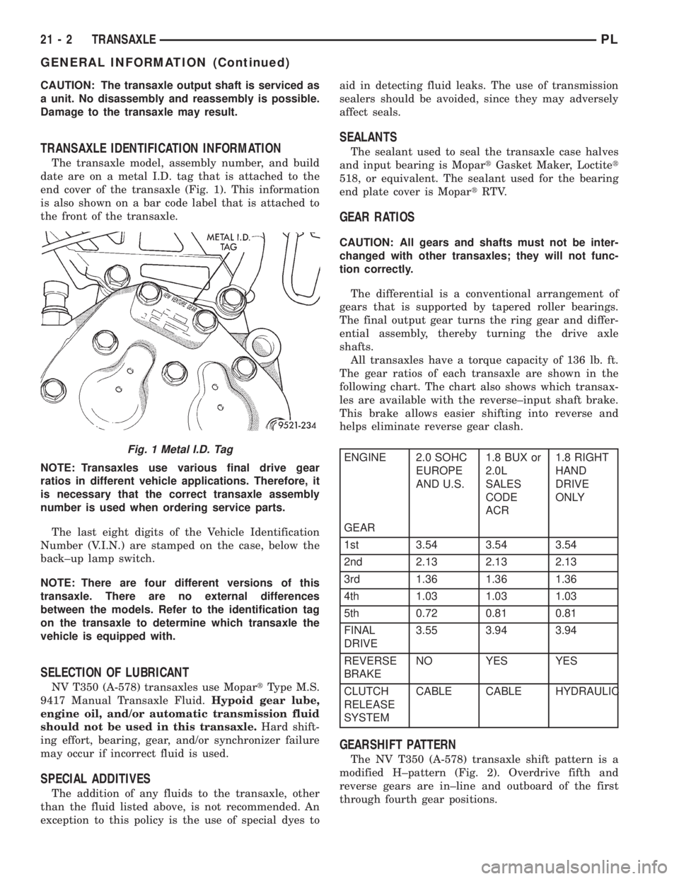
date are on a metal I.D. tag that is attached to the
end cover of the transaxle (Fig. 1). This information
is also shown on a bar code label that is attached to
the front of the transaxle.
NOTE: Transaxles use various final drive gear
ratios in different vehicle applications. Therefore, it
is necessary that the correct transaxle assembly
number is used when ordering service parts.
The last eight digits of the Vehicle Identification
Number (V.I.N.) are stamped on the case, below the
back±up lamp switch.
NOTE: There are four different versions of this
transaxle. There are no external differences
between the models. Refer to the identification tag
on the transaxle to determine which transaxle the
vehicle is equipped with.
SELECTION OF LUBRICANT
NV T350 (A-578) transaxles use MopartType M.S.
9417 Manual Transaxle Fluid.Hypoid gear lube,
engine oil, and/or automatic transmission fluid
should not be used in this transaxle.Hard shift-
ing effort, bearing, gear, and/or synchronizer failure
may occur if incorrect fluid is used.
SPECIAL ADDITIVES
The addition of any fluids to the transaxle, other
than the fluid listed above, is not recommended. An
exception to this policy is the use of special dyes toaid in detecting fluid leaks. The use of transmission
sealers should be avoided, since they may adversely
affect seals.
SEALANTS
The sealant used to seal the transaxle case halves
and input bearing is MopartGasket Maker, Loctitet
518, or equivalent. The sealant used for the bearing
end plate cover is MopartRTV.
GEAR RATIOS
CAUTION: All gears and shafts must not be inter-
changed with other transaxles; they will not func-
tion correctly.
The differential is a conventional arrangement of
gears that is supported by tapered roller bearings.
The final output gear turns the ring gear and differ-
ential assembly, thereby turning the drive axle
shafts.
All transaxles have a torque capacity of 136 lb. ft.
The gear ratios of each transaxle are shown in the
following chart. The chart also shows which transax-
les are available with the reverse±input shaft brake.
This brake allows easier shifting into reverse and
helps eliminate reverse gear clash.
ENGINE 2.0 SOHC
EUROPE
AND U.S.1.8 BUX or
2.0L
SALES
CODE
ACR1.8 RIGHT
HAND
DRIVE
ONLY
GEAR
1st 3.54 3.54 3.54
2nd 2.13 2.13 2.13
3rd 1.36 1.36 1.36
4th 1.03 1.03 1.03
5th 0.72 0.81 0.81
FINAL
DRIVE3.55 3.94 3.94
REVERSE
BRAKENO YES YES
CLUTCH
RELEASE
SYSTEMCABLE CABLE HYDRAULIC
GEARSHIFT PATTERN
The NV T350 (A-578) transaxle shift pattern is a
modified H±pattern (Fig. 2). Overdrive fifth and
reverse gears are in±line and outboard of the first
through fourth gear positions.
Fig. 1 Metal I.D. Tag
21 - 2 TRANSAXLEPL
GENERAL INFORMATION (Continued)
Page 983 of 1200
31TH AUTOMATIC TRANSAXLE
INDEX
page page
GENERAL INFORMATION
FLUID LEVEL AND CONDITION............. 41
GENERAL INFORMATION................. 40
SELECTION OF LUBRICANT............... 41
SPECIAL ADDITIVES..................... 41
DESCRIPTION AND OPERATION
AUTOMATIC TRANSMISSION SHIFTER/
IGNITION INTERLOCK.................. 42
CLUTCHES, BAND SERVOS, AND
ACCUMULATOR....................... 42
FLOW CONTROL VALVES................. 42
GEARSHIFT AND PARKING LOCK CONTROLS . 42
GOVERNOR............................ 43
HYDRAULIC CONTROL SYSTEM............ 42
PRESSURE REGULATING VALVES.......... 42
PRESSURE SUPPLY SYSTEM.............. 42
TORQUE CONVERTER CLUTCH SOLENOID
WIRING CONNECTOR.................. 43
TORQUE CONVERTER CLUTCH............ 42
DIAGNOSIS AND TESTING
CLUTCH AND SERVO AIR PRESSURE TESTS . 54
FLUID LEAKAGE-TRANSAXLE TORQUE
CONVERTER HOUSING AREA............ 55
HYDRAULIC PRESSURE TESTS............ 52
INTERLOCK SYSTEM OPERATION CHECK.... 55
ROAD TEST............................ 52
THREE SPEED TRANSAXLE DIAGNOSIS AND
TESTS.............................. 43
SERVICE PROCEDURES
ALUMINUM THREAD REPAIR.............. 58
FLUID AND FILTER CHANGE............... 56
FLUID DRAIN AND REFILL................. 57
FLUSHING COOLERS AND TUBES.......... 58
OIL PUMP VOLUME CHECK............... 58
REMOVAL AND INSTALLATION
GEARSHIFT CABLE...................... 59
GEARSHIFT MECHANISM................. 60
INTERLOCK MECHANISM................. 63
PARK/NEUTRAL STARTING AND BACK-UP
LAMP SWITCH........................ 64
PUMP OIL SEAL......................... 67
SHIFTER IGNITION INTERLOCK CABLE...... 61THROTTLE PRESSURE CABLE............. 60
TRANSAXLE........................... 64
VEHICLE SPEED SENSOR PINION GEAR..... 64
DISASSEMBLY AND ASSEMBLY
ACCUMULATOR-RECONDITION............ 83
DIFFERENTIAL REPAIR................... 95
FRONT CLUTCH-RECONDITION............ 78
FRONT PLANETARY AND ANNULUS GEAR-
RECONDITION........................ 81
KICKDOWN SERVO (CONTROLLED LOAD)-
RECONDITION........................ 83
LOW/REVERSE (REAR)
SERVO-RECONDITION.................. 82
OIL PUMP-RECONDITION................. 78
OUTPUT SHAFT REPAIR.................. 89
PARKING PAWL......................... 89
REAR CLUTCH-RECONDITION............. 79
TRANSAXLE........................... 67
TRANSFER SHAFT REPAIR................ 83
VALVE BODY RECONDITION............... 74
CLEANING AND INSPECTION
VALVE BODY........................... 99
ADJUSTMENTS
BAND ADJUSTMENT.................... 101
BEARING ADJUSTMENT PROCEDURES..... 101
DIFFERENTIAL BEARING................. 102
GEARSHIFT CABLE...................... 99
HYDRAULIC CONTROL PRESSURE
ADJUSTMENTS....................... 101
OUTPUT SHAFT BEARING................ 102
SHIFTER/IGNITION INTERLOCK SYSTEM.... 100
THROTTLE PRESSURE CABLE ADJUSTMENT
PROCEDURE........................ 100
TRANSFER SHAFT BEARING............. 103
SCHEMATICS AND DIAGRAMS
31TH TRANSAXLE HYDRAULIC SCHEMATIC . 105
SPECIFICATIONS
31TH AUTOMATIC TRANSAXLE............ 113
31TH TRANSAXLE TORQUE
SPECIFICATIONS..................... 113
SPECIAL TOOLS
31TH AUTOMATIC TRANSAXLE............ 114
GENERAL INFORMATION
GENERAL INFORMATION
NOTE: Safety goggles should be worn at all times
when working on these transaxles.This transaxle combines torque converter, three
speed transmission, final drive gearing, and differen-
tial into a front wheel drive system. The identifica-
tion markings and usage of the transaxle are charted
in Diagnosis and Tests.
21 - 40 TRANSAXLEPL
Page 984 of 1200
NOTE: Transaxle operation requirements are differ-
ent for each vehicle and engine combination. Some
internal parts will be different to provide for this.
Therefore, when replacing parts, refer to the seven
digit part number stamped on rear of the transaxle
oil pan flange.
Within this transaxle, there are three primary
areas:
(1) Main center line plus valve body.
(2) Transfer shaft center line (includes governor
and parking sprag).
(3) Differential center line.
Center distances between the main rotating parts
in these three areas are held precise to maintain a
low noise level.
The torque converter, transaxle area, and differen-
tial are housed in an integral aluminum die casting.
The differential oil sump is common with the
transaxle sump. Separate filling of the differen-
tial is NOT necessary.
The torque converter is attached to the crankshaft
through a flexible driving plate. Cooling of the con-
verter is accomplished by circulating the transaxle
fluid through a remote cooler. There are two types of
coolers used. An oil-to-water type cooler located in
the radiator side tank and/or an oil-to-air heat
exchanger. The torque converter assembly is a sealed
unit that cannot be disassembled.
The transaxle fluid is filtered by an internal filter
attached to the lower side of the valve body assembly.
Engine torque is transmitted to the torque con-
verter and then through the input shaft to multiple-
disc clutches in the transaxle. The power flow
depends on the application of the clutches and bands.
Refer to Elements in Use Chart in Diagnosis and
Tests section.
The transaxle consists of:
²Two multiple-disc clutches
²An overrunning clutch
²Two servos
²A hydraulic accumulator
²Two bands
²Two planetary gear sets
This provides three forward ratios and a reverse
ratio. The common sun gear of the planetary gear
sets is connected to the front clutch by a driving
shell. The driving shell is splined to the sun gear and
front clutch retainer. The hydraulic system consists
of an oil pump and a single valve body which con-
tains all of the valves except the governor valves.
The transaxle sump and differential sump are both
vented through the dipstick. Output torque from the
main center line is delivered through helical gears to
the transfer shaft. This gear set is a factor in the
transaxle final drive (axle) ratio. The shaft also car-
ries the governor and parking sprag. An integral heli-cal gear on the transfer shaft drives the differential
ring gear. The final drive gearing is completed with
one of two gear ratios; 2.98 or 3.19 depending on
model and application.
FLUID LEVEL AND CONDITION
NOTE: The transmission and differential sump have
a common oil sump with a communicating opening
between the two.
The torque converter fills in both the P (Park) and
N (Neutral) positions. Place the selector lever in P
(Park) to be sure that the fluid level check is accu-
rate.The engine should be running at idle
speed for at least one minute, with the vehicle
on level ground. This will ensure complete oil
level stabilization between differential and
transmission.The fluid should be at normal operat-
ing temperature (approximately 82É C. or 180É F.).
The fluid level is correct if it is in the HOT region
(cross-hatched area) on the dipstick.
Low fluid level can cause a variety of conditions,
because it allows the pump to take in air along with
the fluid. As in any hydraulic system, air bubbles
make the fluid spongy therefore, pressures will be
low and will build up slowly.
Improper filling also can raise the fluid level too
high. When the transaxle has too much fluid, the
gears churn up foam and cause the same conditions
that occur with a low fluid level.
In either case, the air bubbles can cause overheat-
ing, fluid oxidation, and varnishing. This can inter-
fere with normal valve, clutch, and servo operation.
Foaming also can result in fluid escaping from the
transaxle dipstick, where it may be mistaken for a
leak.
Along with fluid level, it is important to check the
condition of the fluid. When the fluid smells burned,
or is contaminated with metal or friction material
particles, a complete transaxle overhaul is needed.
Be sure to examine the fluid on the dipstick closely.
If there is any doubt about its condition, drain out a
sample for a double check.
SELECTION OF LUBRICANT
It is important that the proper lubricant be used in
these transmissions. Mopar ATF PLUS 3 (Automatic
Transmission Fluid- type 7176) should be used to aid
in ensuring optimum transmission performance. It is
important that the transmission fluid be maintained
at the prescribed level using the recommended fluids.
SPECIAL ADDITIVES
Chrysler Corporation does not recommend the
addition of any fluids to the transmission, other than
that fluid listed above. An exception to this policy is
PLTRANSAXLE 21 - 41
GENERAL INFORMATION (Continued)
Page 999 of 1200
position should not be possible when the ignition
switch is in the LOCK or the ACCESSORY position.
(3) If the interlock system, operates in any way
other than as described above, repair of the interlock
system is required. See Adjustment and Repair pro-
cedures in this section for the required procedures.
SERVICE PROCEDURES
FLUID AND FILTER CHANGE
When the factory fill fluid is changed, only fluids
labeled MOPARtATF PLUS 3 (Automatic Transmis-
sion fluid) Type 7176 should be used.
If the transaxle is disassembled for any reason, the
fluid and filter should be changed.
30,000 MILE TRANSAXLE OIL CHANGE
When a vehicle attains 30,000 miles on its odome-
ter it is recommended that the transaxle oil be
changed. To change the oil, use the procedure that
follows:
It is recommended that a transaxle fluid exchanger
(ATF 2000+ or equivalent) be used to replace the
used fluid in the transaxle. If a fluid exchanger is not
available use a fluid suction pump (Vaculayor equiv-
alent) to draw the fluid out of the dipstick tube. If a
fluid suction pump is not available remove the oil
pan and drain the fluid.
CAUTION: Chrysler Corporation does not recom-
mend using any fluid exchanger that introduces
additives into the transaxle.
TRANSAXLE FLUID EXCHANGER METHOD
(1) To perform the transaxle fluid exchange, the
transaxle must be at operating temperature. Drive
the vehicle till it reaches full operating temperature.
(2) Verify that the fill tank on the transaxle fluid
exchanger (ATF 2000+ or equivalent) is clean and
dry.
(3) Fill the tank to the recommended fill capacity
with Mopar ATF Plus 3 Type 7176.
(4) Hookup the vehicle to the machine following
the manufacturers instructions. Perform the
exchange procedure following the instructions pro-
vided with the machine.
(5) Once machine has completed the fluid
exchange. Check the fluid level and condition and fill
to proper level with Mopar ATF Plus 3 Type 7176.
NOTE: Verify that the transaxle cooler lines are
tightened to proper specifications. Cooler line
torque specification is 2 N²m (18 in. lbs.).DIPSTICK TUBE FLUID SUCTION METHOD
(1) When performing the fluid suction method,
make sure the transaxle is at full operating temper-
ature.
(2) To perform the dipstick tube fluid suction
method, use a suitable fluid suction device (Vaculay
or equivalent).
(3) Insert the fluid suction line into the dipstick
tube.
NOTE: Verify that the suction line is inserted to the
lowest point of the transaxle oil pan. This will
ensure complete evacuation of the fluid in the pan.
(4) Follow the manufacturers recommended proce-
dure and evacuate the fluid from the transaxle.
(5) Remove the suction line from the dipstick tube.
(6) Add 4 Quarts of Mopar ATF Plus 3 Type 7176
transaxle fluid.
(7) Start the engine and allow it to idle for a min-
imum of one minute. With the parking brake applied,
press your foot on the service brake and cycle the
transaxle from park to all gear positions ending in
neutral or park.
(8) Check the transaxle fluid level and add an
appropriate amount to bring the transaxle fluid level
to 3mm (1/8 in.) below the ADD mark on the dip-
stick.
(9) Recheck the fluid level after the transaxle is at
normal operating temperature. The level should be in
the HOT range.
TRANSAXLE OIL PAN DROP METHOD
This procedure involves removing the transaxle oil
pan to drain the transaxle fluid.
(1) Bring the vehicle up to normal operating tem-
perature. Drive the vehicle a minimum of 10 miles.
(2) Raise the vehicle on the hoist.
(3) Loosen the transaxle oil pan and drain the
fluid into a suitable container.
(4) Remove the pan and clean all sealant from the
pan and transaxle mating surfaces. Clean the mag-
net and the inside of the pan.
(5) Apply a 1/8 inch bead of Mopar RTV Sealant to
the mounting flange of the transaxle oil pan. Apply
RTV Sealant to the underside of the attaching bolts.
Attach the oil pan to the transaxle. Tighten the bolts
to 19 N²m (165 in. lbs.).
(6) Lower the vehicle and add 4 Quarts of Mopar
ATF Plus 3 Type 7176 transaxle fluid.
(7) Start the engine and allow it to idle for a min-
imum of one minute. With the parking brake applied,
press your foot on the service brake and cycle the
transaxle from park to all gear positions ending in
neutral or park.
(8) Check the transaxle fluid level and add an
appropriate amount to bring the transaxle fluid level
21 - 56 TRANSAXLEPL
DIAGNOSIS AND TESTING (Continued)