1999 DODGE NEON fuse diagram
[x] Cancel search: fuse diagramPage 150 of 1200
ANTILOCK BRAKE SYSTEM±TEVES MARK 20
INDEX
page page
DESCRIPTION AND OPERATION
ABS BRAKE SYSTEM COMPONENTS........ 71
ABS BRAKES OPERATION AND VEHICLE
PERFORMANCE....................... 69
ABS COMPONENT ABBREVIATION LIST...... 69
ABS FLUID ACCUMULATORS.............. 72
ABS FUSES............................ 73
ABS MASTER CYLINDER AND POWER BRAKE
BOOSTER............................ 71
ABS RELAYS........................... 73
ABS WARNING LAMP (YELLOW)............ 75
ANTILOCK BRAKES OPERATION
DESCRIPTION........................ 69
CONTROLLER ANTILOCK BRAKES (CAB)..... 74
HCU PUMP/MOTOR..................... 72
HYDRAULIC CIRCUITS AND VALVE
OPERATION.......................... 75
INLET VALVES AND SOLENOIDS............ 72
INTEGRATED CONTROL UNIT (ICU)......... 71
OUTLET VALVES AND SOLENOIDS.......... 72
PROPORTIONING VALVE................. 73
WHEEL SPEED SENSORS................. 73
DIAGNOSIS AND TESTING
ABS DIAGNOSTIC TROUBLE CODES........ 78
ABS DIAGNOSTICS MANUAL.............. 76
ABS GENERAL DIAGNOSTICS INFORMATION . 75
ABS SERVICE PRECAUTIONS.............. 76
ABS SYSTEM SELF DIAGNOSTICS.......... 77ABS WIRING DIAGRAM INFORMATION....... 76
BRAKE FLUID CONTAMINATION............ 80
DRB DIAGNOSTIC CONNECTOR............ 77
DRB DIAGNOSTIC SCAN TOOL USAGE...... 77
INTERMITTENT DIAGNOSTIC TROUBLE
CODES.............................. 78
PROPORTIONING VALVE................. 79
TEST DRIVING ABS COMPLAINT VEHICLE.... 80
TONEWHEEL INSPECTION................ 79
SERVICE PROCEDURES
BLEEDING TEVES MARK 20 HYDRAULIC
SYSTEM............................. 81
BRAKE FLUID LEVEL INSPECTION.......... 80
REMOVAL AND INSTALLATION
ABS GENERAL SERVICE PRECAUTIONS..... 81
ABS HYDRAULIC CONTROL UNIT........... 82
CONTROLLER ANTILOCK BRAKES (CAB)..... 86
FRONT WHEEL SPEED SENSOR........... 87
MASTER CYLINDER AND POWER BRAKE
BOOSTER............................ 86
PROPORTIONING VALVES................ 86
REAR WHEEL SPEED SENSOR............ 88
SPECIFICATIONS
BRAKE FASTENER TORQUE SPECIFICATIONS . 89
SPEED SENSOR TONE WHEEL RUNOUT..... 89
WHEEL SPEED SENSOR TO TONE WHEEL
CLEARANCE.......................... 89
DESCRIPTION AND OPERATION
ANTILOCK BRAKES OPERATION DESCRIPTION
The purpose of an Antilock Brake System (ABS) is
to prevent wheel lock-up under braking conditions on
virtually any type of road surface. Antilock Braking
is desirable because a vehicle which is stopped with-
out locking the wheels will retain directional stability
and some steering capability. This allows the driver
to retain greater control of the vehicle during brak-
ing.
This section of the service manual covers the
description and on car service for the ITT Teves
Mark 20 ABS Brake System. If other service is
required on the non ABS related components of the
brake system, refer to the appropriate section in this
group of the service manual for the specific service
procedure required.
ABS COMPONENT ABBREVIATION LIST
In this section of the service manual, several
abbreviations are used for the components of the
Teves Mark 20 ABS Brake System. They are listed
below for your reference.
²CAB±Controller Antilock Brake
²ICU±Integrated Control Unit
²HCU±Hydraulic Control Unit
²ABS±Antilock Brake System
²PSI±Pounds Per Square Inch (pressure)
²WSS±Wheel Speed Sensor
²FWD±Front Wheel Drive
²DTC±Diagnostic Trouble Code
ABS BRAKES OPERATION AND VEHICLE
PERFORMANCE
This ABS System represents the current state-of-
the-art in vehicle braking systems and offers the
driver increased safety and control during braking.
PLBRAKES 5 - 69
Page 157 of 1200
and performance characteristics of the ABS. See the
ABS System Operation Section in this group of the
service manual to familiarize yourself with the oper-
ating principles of the ITT Teves Mark 20 ABS sys-
tem.
ABS SERVICE PRECAUTIONS
The ABS uses an electronic control module, the
CAB. This module is designed to withstand normal
current draws associated with vehicle operation.
Care must be taken to avoid overloading the CAB
circuits.In testing for open or short circuits, do
not ground or apply voltage to any of the cir-
cuits unless instructed to do so for a diagnostic
procedure.These circuits should only be tested
using a high impedance multi-meter or the DRB
tester as described in this section. Power should
never be removed or applied to any control module
with the ignition in the ON position. Before removing
or connecting battery cables, fuses, or connectors,
always turn the ignition to the OFF position.
CAUTION: Use only factory wiring harnesses. Do
not cut or splice wiring to the brake circuits. The
addition of after-market electrical equipment (car
phone, radar detector, citizen band radio, trailer
lighting, trailer brakes, ect.) on a vehicle equippedwith antilock brakes may affect the function of the
antilock brake system.
ABS WIRING DIAGRAM INFORMATION
During the diagnosis of the antilock brake system
it may become necessary to reference the wiring dia-
grams covering the antilock brake system and its
components. For wiring diagrams refer to Antilock
Brakes in Group 8W of this service manual. This
group will provide you with the wiring diagrams and
the circuit description and operation information cov-
ering the antilock brake system.
ABS DIAGNOSTICS MANUAL
Detailed procedures for diagnosing specific ABS
conditions are covered in the diagnostics manual cov-
ering the ITT Teves Mark 20 ABS system. The fol-
lowing information is presented to give the
technician a general background on the diagnostic
capabilities of the ITT Teves Mark 20 ABS system.
Please refer to the above mentioned manual for any
further electronic diagnostics and service procedures
that are required.
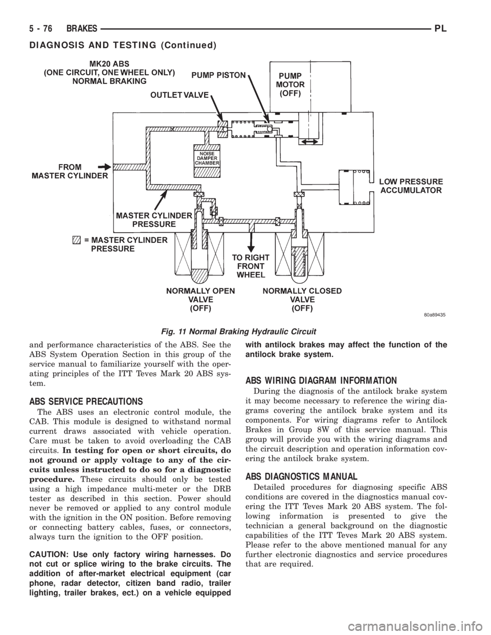
Fig. 11 Normal Braking Hydraulic Circuit
5 - 76 BRAKESPL
DIAGNOSIS AND TESTING (Continued)
Page 160 of 1200
A visual inspection for loose, disconnected, or mis-
routed wires should be done before attempting to
diagnose or service the ITT Teves Mark 20 antilock
brake system. A visual inspection will eliminate
unnecessary testing and diagnostics time. A thorough
visual inspection will include the following compo-
nents and areas of the vehicle.
(1) Inspect fuses in the power distribution center
(PDC) and the wiring junction block. Verify that all
fuses are fully inserted into the PDC and wring junc-
tion block. A label on the underside of the PDC cover
identifies the locations of the ABS fuses in the PDC.
(2) Inspect the 25-way electrical connector at the
CAB for damage, spread or backed-out wiring termi-
nals. Verify that the 25-way connector is fully
inserted in the socket on the CAB. Be sure that wires
are not stretched tight or pulled out of the connector.
(3) Verify that all the wheel speed sensor connec-
tions are secure.
(4) Poor mating of connector halves or terminals
not fully seated in the connector body.
(5) Improperly formed or damaged terminals. All
connector terminals in a suspect circuit should be
carefully reformed to increase contact tension.
(6) Poor terminal to wire connection. This requires
removing the terminal from the connector body to
inspect.
(7) Pin presence in the connector assembly
(8) Proper ground connections. Check all ground
connections for signs of corrosion, tight fasteners, or
other potential defects. Refer to wiring diagram man-
ual for ground locations.
(9) Problems with main power sources of the vehi-
cle. Inspect battery, generator, ignition circuits and
other related relays and fuses.
(10) If a visual check does not find the cause of the
problem, operate the car in an attempt to duplicate
the condition and record the trouble code.
(11) Most failures of the ABS system will disable
ABS function for the entire ignition cycle even if the
fault clears before key-off. There are some failure
conditions, however, which will allow ABS operation
to resume during the ignition cycle in which a failure
occurred if the failure conditions are no longer
present. The following conditions may result in inter-
mittent illumination of the ABS Warning Lamp. All
other failures will cause the lamp to remain on until
the ignition switch is turned off. Circuits involving
these inputs to the CAB should be investigated if a
complaint of intermittent warning system operation
is encountered.
(12) Low system voltage. If Low System Voltage is
detected by the CAB, the CAB will turn on the ABS
Warning Lamp until normal system voltage is
achieved. Once normal voltage is seen at the CAB,
normal operation resumes.(13) High system voltage. If high system voltage is
detected by the CAB, the CAB will turn on the
Amber ABS Warning Lamp until normal system volt-
age is achieved. Once normal voltage is again
detected by the CAB, normal ABS operation resumes.
(14) Additionally, any condition which results in
interruption of electrical current to the CAB or mod-
ulator assembly may cause the ABS Warning Lamp
to turn on intermittently.
(15) The body controller can turn on the (yellow)
ABS warning lamp if CCD communication between
the body controller and the CAB is interupted.
TONEWHEEL INSPECTION
CAUTION: The tone wheels used on this vehicle
equipped with the Teves Mark 20 Antilock Brake
System are different then those used on past mod-
els of this vehicle equipped with antilock brakes.
Reduced braking performance will result if this part
is used on earlier model vehicles and an accident
could result. Do not use on pre-1998 model year
vehicles.
Carefully inspect tonewheel at the suspected faulty
wheel speed sensor for missing, chipped or broken
teeth, this can cause erratic speed sensor signals.
Tonewheels should show no evidence of contact
with the wheel speed sensors. If contact was made,
determine cause and correct before replacing the
wheel speed sensor.
Excessive runout of the tonewheel can cause
erratic wheel speed sensor signals. Refer to Tone-
wheel Runout in the Specification Section in this sec-
tion of the service manual for the tonewheel runout
specification. Replace drive shaft assembly or rear
hub/bearing assembly if tonewheel runout exceeds
the specification.
Inspect tonewheels for looseness on their mounting
surfaces. Tonewheels are pressed onto their mounting
surfaces and should not rotate independently from
the mounting surface.
Check the wheel speed sensor head alignment to
the tone wheel. Also check the gap between the speed
sensor head and the tone wheel to ensure it is at
specification. Refer to Wheel Speed Sensor Clearance
in the Specification Section in this section of the ser-
vice manual.
PROPORTIONING VALVE
CAUTION: Proportioning valves should never be
disassembled.
If premature rear wheel skid occurs on a hard
brake application, it could be an indication that a
PLBRAKES 5 - 79
DIAGNOSIS AND TESTING (Continued)
Page 220 of 1200
NOTE: BLACK OR DARK=0to75%state-of-charge
The battery is INADEQUATELY charged and must
be charged until green dot is visible, (12.4 volts or
greater) before the battery is tested or returned to
use. Refer to Causes of Battery Discharging in this
Group for more information.
NOTE: CLEAR COLOR = Replace Battery
WARNING: DO NOT CHARGE, ASSIST BOOST,
LOAD TEST, OR ADD WATER TO THE BATTERY
WHEN CLEAR COLOR DOT IS VISIBLE. PERSONAL
INJURY MAY OCCUR.
A clear color dot shows electrolyte level in battery
is below the test indicator (Fig. 1). Water cannot be
added to a maintenance free battery. The battery
must be replaced. A low electrolyte level may be
caused by an over charging condition. Refer to Gen-
erator Test Procedures on Vehicle.
CAUSES OF BATTERY DISCHARGING
It is normal to have a small 5 to 25 milliamperes
continuous electrical draw from the battery. This
draw will take place with the ignition in the OFF
position, and the courtesy, dome, storage compart-
ments, and engine compartment lights OFF. The con-
tinuous draw is due to various electronic features or
accessories that require electrical current with the
ignition OFF to function properly. When a vehicle is
not used over an extended period of approximately 20
days the IOD fuse should be pulled. The fuse is
located in the power distribution center. removal of
this fuse will reduce the level of battery discharge.
Refer to the Battery Diagnosis and Testing Table for
proper diagnosis.
ABNORMAL BATTERY DISCHARGING
²Corroded battery posts, cables or terminals.
²Loose or worn generator drive belt.
²Electrical loads that exceed the output of the
charging system due to equipment or accessories
installed after delivery.
²Slow driving speeds in heavy traffic conditions
or prolonged idling with high-amperage electrical
systems in use.
²Defective electrical circuit or component causing
excess Ignition Off Draw (IOD). Refer to Battery
Ignition Off Draw (IOD).
²Defective charging system.
²Defective battery.
BATTERY IGNITION OFF DRAW (IOD)
High current draw on the battery with the ignition
OFF will discharge a battery. After a dead battery is
recharged, the vehicle ignition off draw (IOD) shouldbe checked. To determine if a high current draw con-
dition exists first check the vehicle with a test lamp.
(1) Verify that all electrical accessories are OFF.
²Remove key from ignition switch
²Turn off all lights
²Trunk lid is closed
²Engine compartment hood lamp is disconnected
or lamp removed
²Glove box door is closed
²Sun visor vanity lights are OFF
²All doors are closed
²Allow the ignition key lamp system to time out
in approximately 30 seconds, if equipped.
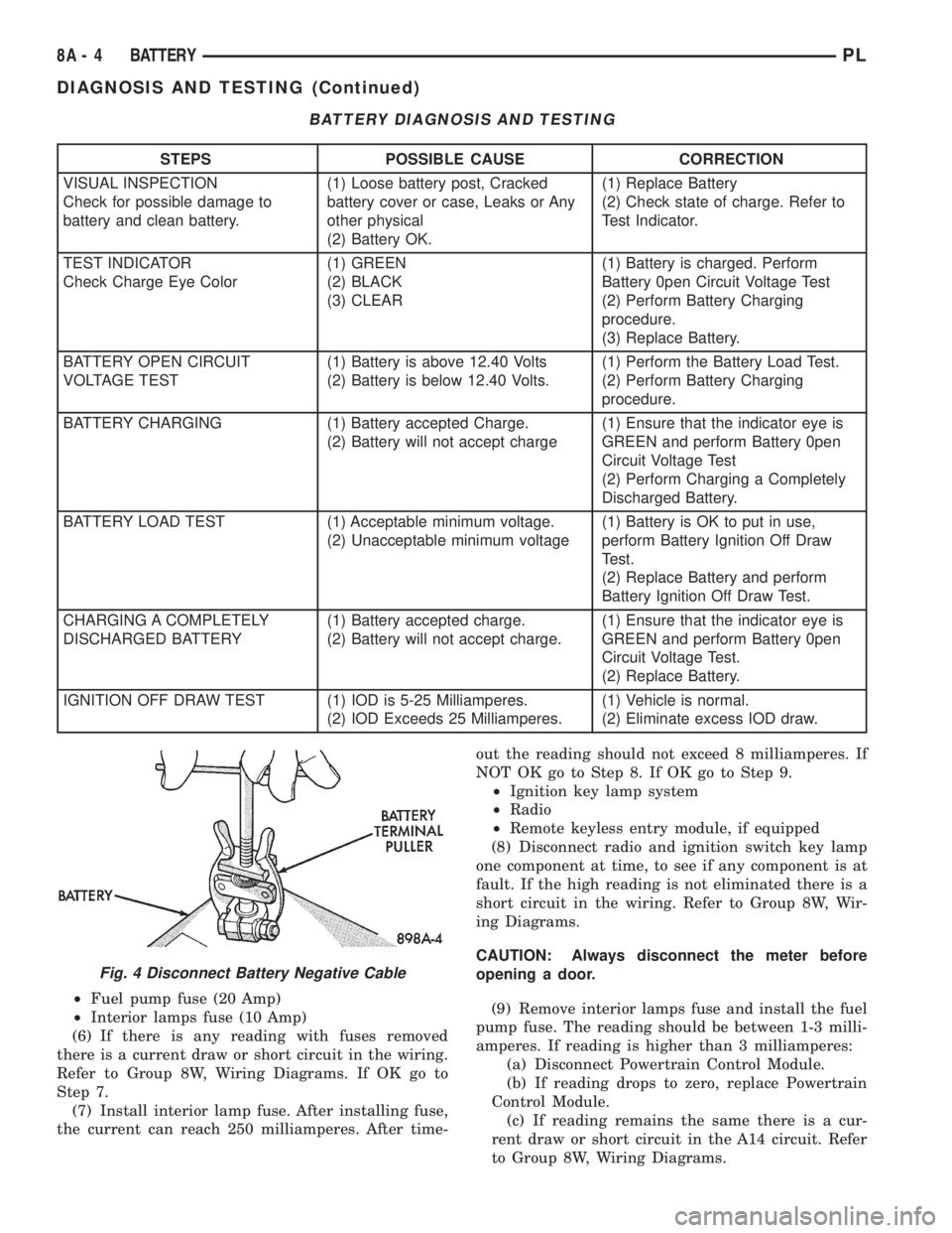
(2) Disconnect battery negative cable (Fig. 4).
(3) Connect a 12 Volt test lamp, with a cold resis-
tance of 5-7 ohms, between the battery negative cable
clamp and the negative post (Fig. 5). If test lamp
goes out system is OK. If test lamp lights and stays
ON, go to Test Lamp Stays ON procedure.
TEST LAMP STAYS ON
There is either a short circuit or a fault in an elec-
tronic module. Two fuses in the Power Distribution
Center (PDC) feed the modules with ignition off
draw.
²Interior lamps fuse (10 Amp) (IOD) PDC.
²Fuel pump fuse (20 Amp) in PDC
(1) Remove interior lamp and fuel pump fuses. By
removing these fuses all ignition off draw from the
vehicle electronics will be disconnected. The test
lamp should go out. If test lamp goes out go to Step
2. If test lamp does not go out there is a current
draw or short circuit. Refer to Group 8W, Wiring Dia-
grams.
(2) Install the fuel pump fuse. If test lamp lights,
there is a current draw or short circuit in the A14
wiring circuit feed.
(a) Disconnect Powertrain Control Module.
(b) If test lamp goes out, replace Powertrain
Control Module.
(c) If test lamp does not go out, there is a cur-
rent draw or short circuit in the A14 circuit feed.
Refer to Group 8W, Wiring Diagrams.
(3) Install the interior lamp fuse. If test lamp
lights, there is a current draw or short circuit in the
M01 circuit. Refer to Group 8W, Wiring Diagrams. If
test lamp stays out, go to Step 4
(4) Use a multi-meter that has at least a range of
200 milliamperes. Install meter between the battery
negative cable and battery negative post (Fig. 6).
Carefully remove the test lamp without disconnecting
the meter. After all modules time-out the total vehi-
cle IOD should be less than 10 milliamperes. If igni-
tion off draw is more than 10 milliamperes go to Step
5.
(5) Remove both fuses from the Power Distribution
Center:
PLBATTERY 8A - 3
DIAGNOSIS AND TESTING (Continued)
Page 221 of 1200
²Fuel pump fuse (20 Amp)
²Interior lamps fuse (10 Amp)
(6) If there is any reading with fuses removed
there is a current draw or short circuit in the wiring.
Refer to Group 8W, Wiring Diagrams. If OK go to
Step 7.
(7) Install interior lamp fuse. After installing fuse,
the current can reach 250 milliamperes. After time-out the reading should not exceed 8 milliamperes. If
NOT OK go to Step 8. If OK go to Step 9.
²Ignition key lamp system
²Radio
²Remote keyless entry module, if equipped
(8) Disconnect radio and ignition switch key lamp
one component at time, to see if any component is at
fault. If the high reading is not eliminated there is a
short circuit in the wiring. Refer to Group 8W, Wir-
ing Diagrams.
CAUTION: Always disconnect the meter before
opening a door.
(9) Remove interior lamps fuse and install the fuel
pump fuse. The reading should be between 1-3 milli-
amperes. If reading is higher than 3 milliamperes:
(a) Disconnect Powertrain Control Module.
(b) If reading drops to zero, replace Powertrain
Control Module.
(c) If reading remains the same there is a cur-
rent draw or short circuit in the A14 circuit. Refer
to Group 8W, Wiring Diagrams.
BATTERY DIAGNOSIS AND TESTING
STEPS POSSIBLE CAUSE CORRECTION
VISUAL INSPECTION
Check for possible damage to
battery and clean battery.(1) Loose battery post, Cracked
battery cover or case, Leaks or Any
other physical
(2) Battery OK.(1) Replace Battery
(2) Check state of charge. Refer to
Test Indicator.
TEST INDICATOR
Check Charge Eye Color(1) GREEN
(2) BLACK
(3) CLEAR(1) Battery is charged. Perform
Battery 0pen Circuit Voltage Test
(2) Perform Battery Charging
procedure.
(3) Replace Battery.
BATTERY OPEN CIRCUIT
VOLTAGE TEST(1) Battery is above 12.40 Volts
(2) Battery is below 12.40 Volts.(1) Perform the Battery Load Test.
(2) Perform Battery Charging
procedure.
BATTERY CHARGING (1) Battery accepted Charge.
(2) Battery will not accept charge(1) Ensure that the indicator eye is
GREEN and perform Battery 0pen
Circuit Voltage Test
(2) Perform Charging a Completely
Discharged Battery.
BATTERY LOAD TEST (1) Acceptable minimum voltage.
(2) Unacceptable minimum voltage(1) Battery is OK to put in use,
perform Battery Ignition Off Draw
Test.
(2) Replace Battery and perform
Battery Ignition Off Draw Test.
CHARGING A COMPLETELY
DISCHARGED BATTERY(1) Battery accepted charge.
(2) Battery will not accept charge.(1) Ensure that the indicator eye is
GREEN and perform Battery 0pen
Circuit Voltage Test.
(2) Replace Battery.
IGNITION OFF DRAW TEST (1) IOD is 5-25 Milliamperes.
(2) IOD Exceeds 25 Milliamperes.(1) Vehicle is normal.
(2) Eliminate excess IOD draw.
Fig. 4 Disconnect Battery Negative Cable
8A - 4 BATTERYPL
DIAGNOSIS AND TESTING (Continued)
Page 252 of 1200

Plastic clips in various locations protect the cables
from damage. When the cables are replaced the clips
must be used to prevent damage to the cables. The
#1 cable must be routed under the PCV hose and
clipped to the #2 cable.
ELECTRONIC IGNITION COILS
WARNING: THE DIRECT IGNITION SYSTEM GEN-
ERATES APPROXIMATELY 40,000 VOLTS. PER-
SONAL INJURY COULD RESULT FROM CONTACT
WITH THIS SYSTEM.
The coil pack consists of 2 coils molded together.
The coil pack is mounted on the valve cover (Fig. 3)
or (Fig. 4). High tension leads route to each cylinder
from the coil. The coil fires two spark plugs every
power stroke. One plug is the cylinder under com-
pression, the other cylinder fires on the exhaust
stroke. Coil number one fires cylinders 1 and 4. Coil
number two fires cylinders 2 and 3. The PCM deter-
mines which of the coils to charge and fire at the cor-
rect time.
The Auto Shutdown (ASD) relay provides battery
voltage to the ignition coil. The PCM provides a
ground contact (circuit) for energizing the coil. When
the PCM breaks the contact, the energy in the coil
primary transfers to the secondary causing the
spark. The PCM will de-energize the ASD relay if it
does not receive the crankshaft position sensor and
camshaft position sensor inputs. Refer to Auto Shut-
down (ASD) RelayÐPCM Output, in this section for
relay operation.
AUTOMATIC SHUTDOWN RELAY
The Automatic Shutdown (ASD) relay supplies bat-
tery voltage to the fuel injectors, electronic ignition
coil and the heating elements in the oxygen sensors.
A buss bar in the Power Distribution Center (PDC)
supplies voltage to the solenoid side and contact sideof the relay. The ASD relay power circuit contains a
20 amp fuse between the buss bar in the PDC and
the relay. The fuse also protects the power circuit for
the fuel pump relay and pump. The fuse is located in
the PDC. Refer to Group 8W, Wiring Diagrams for
circuit information.
The PCM controls the ASD relay by switching the
ground path for the solenoid side of the relay on and
off. The PCM turns the ground path off when the
ignition switch is in the Off position. When the igni-
tion switch is in On or Start, the PCM monitors the
crankshaft and camshaft position sensor signals to
determine engine speed and ignition timing (coil
dwell). If the PCM does not receive crankshaft and
camshaft position sensor signals when the ignition
switch is in the Run position, it will de-energize the
ASD relay.
The ASD relay is located in the PDC (Fig. 5). The
inside top of the PDC cover has label showing relay
and fuse identification.
Fig. 3 Ignition Coil PackÐSOHC
Fig. 4 Ignition Coil PackÐDOHC
Fig. 5 Power Distribution Center (PDC)
PLIGNITION SYSTEM 8D - 3
DESCRIPTION AND OPERATION (Continued)
Page 288 of 1200
AUDIO SYSTEM
CONTENTS
page page
GENERAL INFORMATION
INTRODUCTION......................... 1
DESCRIPTION AND OPERATION
INTERFERENCE ELIMINATION.............. 1
DIAGNOSIS AND TESTING
ANTENNA.............................. 3
AUDIO DIAGNOSTIC TEST PROCEDURES..... 1BENCH TEST FOR ANTENNA MALFUNCTION . . 3
REMOVAL AND INSTALLATION
ANTENNA.............................. 3
FRONT DOOR SPEAKER................... 4
INSTRUMENT PANEL SPEAKER............. 4
RADIO................................. 4
REAR SHELF SPEAKER(S)................. 5
GENERAL INFORMATION
INTRODUCTION
Operating instructions for the factory installed
audio systems can be found in the Owner's Manual
provided with the vehicle.
The vehicles are equipped with an Interior (Igni-
tion Off Draw) fuse in the Power Distribution Center
located in the engine compartment. After the Interior
(IOD) fuse or battery has been disconnected the clock
will require resetting.
DESCRIPTION AND OPERATION
INTERFERENCE ELIMINATION
The radio utilizes a ground wire plugged on to a
blade terminal and is bolted to the radio chassis.
Both connector and terminal should be securely
attached. The engine has three separate ground
straps to suppress ignition noise which may interfere
with radio reception.
²Left engine mount clip on strap
²Engine to shock tower reinforcement
²Rear strut to body, clip-on strap
Inductive type spark plug cables in the high ten-
sion circuit of the ignition system complete the inter-
ference suppression. Faulty or deteriorated spark
plug wires should be replaced.
In addition, there is a capacitor mounted on the
cylinder head which also helps suppress ignition
noise.
DIAGNOSIS AND TESTING
AUDIO DIAGNOSTIC TEST PROCEDURES
CAUTION: The CD player will only operate between
approximate temperatures of -23ÉC and +65ÉC (-10ÉF
and +145ÉF).
Whenever a radio malfunction occurs;
(1) First check FUSES:
(a) Power Distribution Center (PDC), Interior
lamp fuse, M1 - Radio Memory Feed
(b) Fuse Block:
(I) Fuse 12, Illumination in the fuse block
(II) Fuse 16, Ignition feed in the fuse block
NOTE: The vehicles are shipped with the INTERIOR
LAMP fuse disconnected.
(2) Verify, the radio wire harness are properly con-
nected before starting normal diagnosis and repair
procedures. Refer to Audio Diagnosis table and/or
Group 8W, Wiring Diagrams, Radio Section.
PLAUDIO SYSTEM 8F - 1
Page 294 of 1200
HORNS
CONTENTS
page page
DESCRIPTION AND OPERATION
INTRODUCTION......................... 1
DIAGNOSIS AND TESTING
HORN RELAY........................... 2
HORN SWITCH.......................... 2
HORN................................. 1SYSTEM TEST.......................... 2
REMOVAL AND INSTALLATION
HORN RELAY........................... 4
HORN SWITCHES........................ 4
HORN................................. 4
DESCRIPTION AND OPERATION
INTRODUCTION
WARNING: ON VEHICLES EQUIPPED WITH AIR-
BAG, SEE GROUP 8M, RESTRAINT SYSTEMS FOR
STEERING WHEEL OR COLUMN REMOVAL PROCE-
DURES.
The horn circuit consists of a horn switch, horn
relay, and horn. The horn circuit feed is from the fuse
to the horn relay in the Power Distribution Center
(PDC). The PDC is mounted on the battery tray.
When the horn switch is depressed, it completes the
ground circuit. The horn relay coil closes contacts
and allows current to flow to the horn. The horn is
grounded to the headlamp ground connection (Fig. 1)
.
HORN SWITCH
The horn switch is mounted between the outer and
inner cover of the Driver Airbag Module (Fig. 2).
When the Driver Airbag is pressed the horn switch
makes contact to ground. The ground signal is car-
ried to the horn relay and the horn sounds.
(1) The horn switch grounds to the airbag housing.(2) If horn does not sound check for corrosion:
²Horn wire
²Horn switch ground connected to airbag metal
housing
²Airbag to steering wheel
²Ensure horn wire is properly connected and
insulator is in place on wire
(3) Refer to Group 8W, Wiring Diagrams if wire
circuit needs to be repaired.
DIAGNOSIS AND TESTING
HORN
(1) Disconnect wire connector at horn.
(2) Using a voltmeter, connect one lead to ground
terminal and the other lead to the positive wire ter-
minal (Fig. 3).
(3) Depress the horn switch, battery voltage
should be present.
(4) If no voltage, refer to Horn System Test. If volt-
age is OK, go to Step 5.
Fig. 1 Horn System
Fig. 2 Horn Switch
PLHORNS 8G - 1