1999 DODGE NEON fuse diagram
[x] Cancel search: fuse diagramPage 368 of 1200
ELECTRICALLY HEATED SYSTEMS
CONTENTS
page page
DIAGNOSIS AND TESTING
REAR WINDOW DEFOGGER SWITCH....... 1REMOVAL AND INSTALLATION
REAR WINDOW DEFOGGER AND/OR REAR
FOG LAMP SWITCH................... 2
DIAGNOSIS AND TESTING
REAR WINDOW DEFOGGER SWITCH
The rear window defogger switch may be tested in-
vehicle or bench tested. In vehicle testing is accom-
plished in the following manner:
(1) Remove the switch from the instrument panel
but leave the switch connected, refer to Group 8E,
Instrument Panel and Systems for removal proce-
dures.
(2) Turn the ignition switch ON.
(3) Using a voltmeter, check for battery voltage at
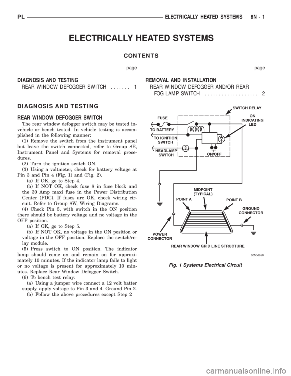
Pin 3 and Pin 4 (Fig. 1) and (Fig. 2).
(a) If OK, go to Step 4.
(b) If NOT OK, check fuse 8 in fuse block and
the 30 Amp maxi fuse in the Power Distribution
Center (PDC). If fuses are OK, check wiring cir-
cuit. Refer to Group 8W, Wiring Diagrams.
(4) Check Pin 5, with switch in the ON position
there should be battery voltage and no voltage in the
OFF position.
(a) If OK, go to Step 5.
(b) If NOT OK, no voltage in the ON position or
voltage in the OFF position. Replace the switch/re-
lay module.
(5) Press switch to ON position. The indicator
lamp should come on and remain on for approxi-
mately 10 minutes. If the indicator lamp fails to light
or no voltage is present for approximately 10 min-
utes. Replace Rear Window Defogger Switch.
(6) To bench test relay:
(a) Using a jumper wire connect a 12 volt batter
supply, apply voltage to Pin 3 and 4. Ground Pin 2.
(b) Follow the above procedures except Step 2
Fig. 1 Systems Electrical Circuit
PLELECTRICALLY HEATED SYSTEMS 8N - 1
Page 378 of 1200
SERVICE PROCEDURES
VEHICLE IMMOBILIZER SYSTEM
WARNING: ON VEHICLES EQUIPPED WITH AIR-
BAGS, REFER TO GROUP 8M - PASSIVE
RESTRAINT SYSTEMS BEFORE ATTEMPTING ANY
STEERING WHEEL, STEERING COLUMN, OR
INSTRUMENT PANEL COMPONENT DIAGNOSIS OR
SERVICE. FAILURE TO TAKE THE PROPER PRE-
CAUTIONS COULD RESULT IN ACCIDENTAL AIR-
BAG DEPLOYMENT AND POSSIBLE PERSONAL
INJURY.
NOTE: The following tests may not prove conclu-
sive in the diagnosis of this system. The most reli-
able, efficient, and accurate means to diagnose the
Vehicle Immobilizer System involves the use of a
DRB scan tool. Refer to the Vehicle Theft Security
System menu item on the DRB scan tool for the
procedures.
The vehicle immobilizer system and the Chrysler
Collision Detection (CCD) data bus network should
be diagnosed using the DRB scan tool. The DRB will
allow confirmation that the CCD data bus is func-
tional, that the immobilizer receiver is placing the
proper messages on the CCD data bus, and that the
Powertrain Control Module (PCM) is receiving the
CCD data bus messages. Refer to the Vehicle Theft
Security System menu item on the DRB scan tool for
the procedures. Refer to 8W-39 - Vehicle Theft Secu-
rity System in Group 8W - Wiring Diagrams for com-
plete circuit descriptions and diagrams.
(1) With the ignition switch in the Off position,
depress the Lock or Unlock button of the immobilizer
transmitter. Listen for the immobilizer receiver to
issue an audible chirp (Unlock) or chirps (Lock). If
OK, go to Step 2. If not OK, replace the transmitter
batteries with known good units and repeat Step 1. If
still not OK, go to Step 2.
(2) Check the fuse in the Power Distribution Cen-
ter (PDC). If OK, go to Step 3. If not OK, repair the
shorted circuit or component as required and replace
the faulty fuse.
(3) Disconnect and isolate the battery negative
cable. Unplug the wire harness connector at the
immobilizer receiver. Check for continuity between
the ground circuit cavity of the immobilizer receiver
wire harness connector and a good ground. There
should be continuity. If OK, go to Step 4. If not OK,
repair the open circuit to ground as required.
(4) Connect the battery negative cable. Check for
battery voltage at the fused B(+) circuit cavity of the
immobilizer receiver wire harness connector. If OK,
refer to the Vehicle Theft Security System menu itemon the DRB scan tool for further diagnosis. If not
OK, repair the open circuit to the PDC fuse as
required.REMOVAL AND INSTALLATION
IMMOBILIZER RECEIVER
WARNING: ON VEHICLES EQUIPPED WITH AIR-
BAGS, REFER TO GROUP 8M - PASSIVE
RESTRAINT SYSTEMS BEFORE ATTEMPTING ANY
STEERING WHEEL, STEERING COLUMN, OR
INSTRUMENT PANEL COMPONENT DIAGNOSIS OR
SERVICE. FAILURE TO TAKE THE PROPER PRE-
CAUTIONS COULD RESULT IN ACCIDENTAL AIR-
BAG DEPLOYMENT AND POSSIBLE PERSONAL
INJURY.
(1) Disconnect and isolate the battery negative
cable.
(2) Remove the Instrument Panel Top Cover and
Cluster Bezel and Right Trim panel. Remove the
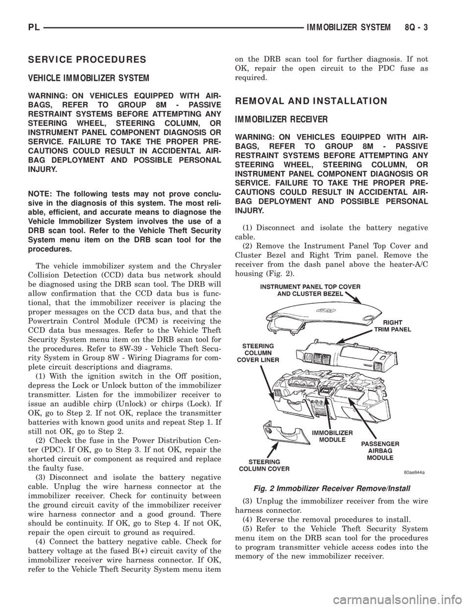
receiver from the dash panel above the heater-A/C
housing (Fig. 2).
(3) Unplug the immobilizer receiver from the wire
harness connector.
(4) Reverse the removal procedures to install.
(5) Refer to the Vehicle Theft Security System
menu item on the DRB scan tool for the procedures
to program transmitter vehicle access codes into the
memory of the new immobilizer receiver.
Fig. 2 Immobilizer Receiver Remove/Install
PLIMMOBILIZER SYSTEM 8Q - 3
Page 380 of 1200
POWER WINDOWS
CONTENTS
page page
GENERAL INFORMATION
INTRODUCTION......................... 1
DIAGNOSIS AND TESTING
WINDOW MOTOR TEST................... 1
WINDOW SWITCH TEST.................. 1WIRING TEST........................... 1
REMOVAL AND INSTALLATION
2 DOOR WINDOW MOTOR................ 2
4 DOOR WINDOW MOTOR................ 3
WINDOW SWITCH....................... 2
GENERAL INFORMATION
INTRODUCTION
The window lift motors are of the permanent mag-
net type. A battery positive and negative connection
to either of the two motor terminals will cause the
motor to rotate in one direction. Reversing current
through these same two connections will cause the
motor to rotate in the opposite direction.
Each individual motor is grounded through the
master switch.
DIAGNOSIS AND TESTING
WIRING TEST
The following wiring test determines whether or
not voltage is continuous through the body harness
to switch.
Remove switch for testing. Connect a voltmeter
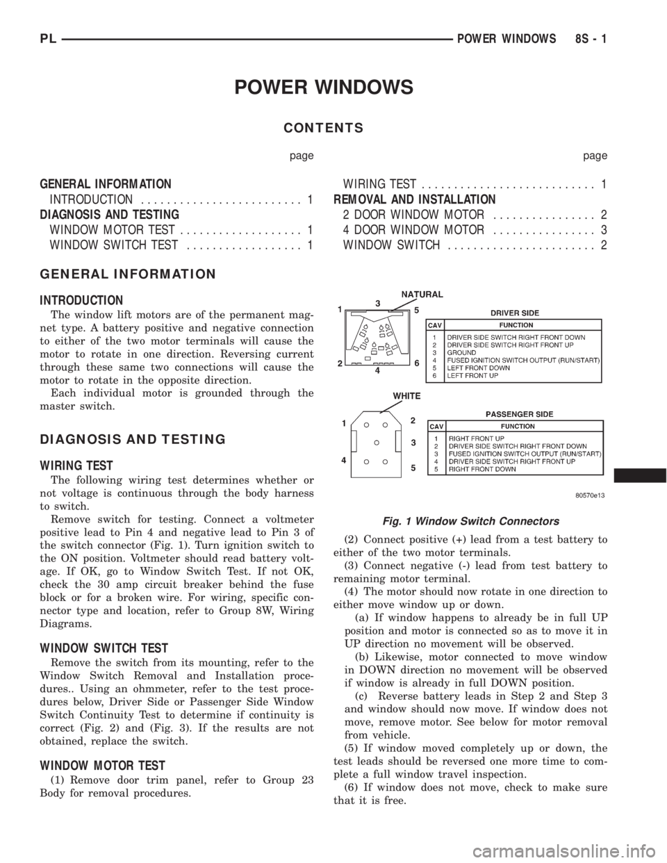
positive lead to Pin 4 and negative lead to Pin 3 of
the switch connector (Fig. 1). Turn ignition switch to
the ON position. Voltmeter should read battery volt-
age. If OK, go to Window Switch Test. If not OK,
check the 30 amp circuit breaker behind the fuse
block or for a broken wire. For wiring, specific con-
nector type and location, refer to Group 8W, Wiring
Diagrams.
WINDOW SWITCH TEST
Remove the switch from its mounting, refer to the
Window Switch Removal and Installation proce-
dures.. Using an ohmmeter, refer to the test proce-
dures below, Driver Side or Passenger Side Window
Switch Continuity Test to determine if continuity is
correct (Fig. 2) and (Fig. 3). If the results are not
obtained, replace the switch.
WINDOW MOTOR TEST
(1) Remove door trim panel, refer to Group 23
Body for removal procedures.(2) Connect positive (+) lead from a test battery to
either of the two motor terminals.
(3) Connect negative (-) lead from test battery to
remaining motor terminal.
(4) The motor should now rotate in one direction to
either move window up or down.
(a) If window happens to already be in full UP
position and motor is connected so as to move it in
UP direction no movement will be observed.
(b) Likewise, motor connected to move window
in DOWN direction no movement will be observed
if window is already in full DOWN position.
(c) Reverse battery leads in Step 2 and Step 3
and window should now move. If window does not
move, remove motor. See below for motor removal
from vehicle.
(5) If window moved completely up or down, the
test leads should be reversed one more time to com-
plete a full window travel inspection.
(6) If window does not move, check to make sure
that it is free.
Fig. 1 Window Switch Connectors
PLPOWER WINDOWS 8S - 1
Page 392 of 1200
WIRING DIAGRAMS
CONTENTS
page page
AIR CONDITIONING-HEATER.......... 8W-42-1
AIRBAG SYSTEM................... 8W-43-1
ANTI-LOCK BRAKES................. 8W-35-1
AUDIO SYSTEMS................... 8W-47-1
CHARGING SYSTEM................. 8W-20-1
COMPONENT INDEX................. 8W-02-1
CONNECTOR/GROUND LOCATIONS..... 8W-90-1
CONNECTOR PIN-OUTS.............. 8W-80-1
FRONT LIGHTING................... 8W-50-1
FUEL/IGNITION SYSTEMS............ 8W-30-1
FUSE BLOCK....................... 8W-11-1
GENERAL INFORMATION............. 8W-01-1
GROUND DISTRIBUTION............. 8W-15-1
HORN/CIGAR LIGHTER............... 8W-41-1INSTRUMENT CLUSTER.............. 8W-40-1
INTERIOR LIGHTING................. 8W-44-1
POWER DISTRIBUTION.............. 8W-10-1
POWER DOOR LOCKS............... 8W-61-1
POWER MIRRORS.................. 8W-62-1
POWER SUNROOF.................. 8W-64-1
POWER WINDOWS.................. 8W-60-1
REAR LIGHTING.................... 8W-51-1
REAR WINDOW DEFOGGER........... 8W-48-1
SPLICE INFORMATION............... 8W-70-1
SPLICE LOCATIONS................. 8W-95-1
STARTING SYSTEM................. 8W-21-1
TURN SIGNALS..................... 8W-52-1
WIPERS........................... 8W-53-1
PLWIRING DIAGRAMS 8W - 1
Page 397 of 1200
CIRCUIT INFORMATION
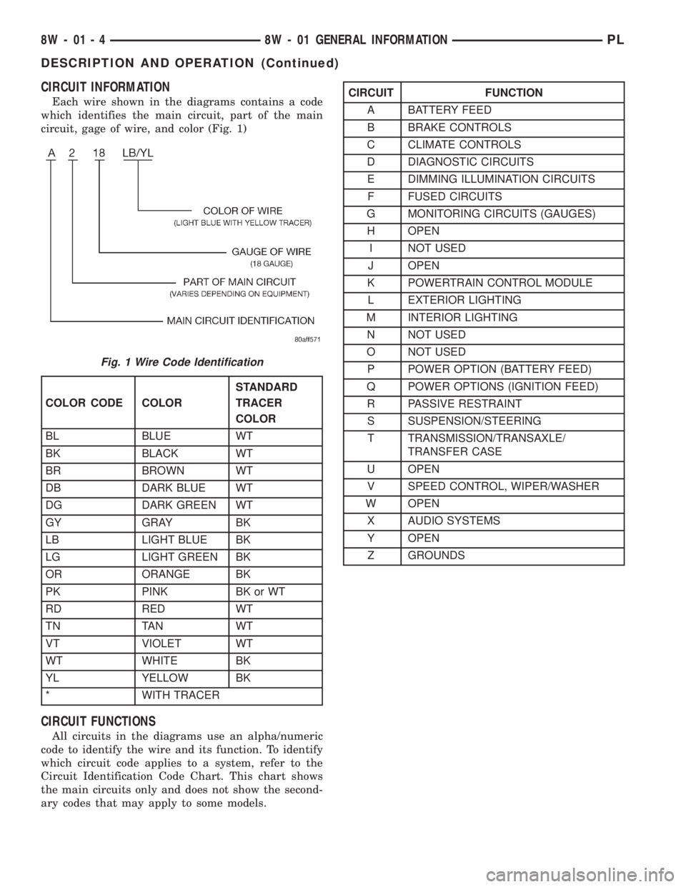
Each wire shown in the diagrams contains a code
which identifies the main circuit, part of the main
circuit, gage of wire, and color (Fig. 1)
CIRCUIT FUNCTIONS
All circuits in the diagrams use an alpha/numeric
code to identify the wire and its function. To identify
which circuit code applies to a system, refer to the
Circuit Identification Code Chart. This chart shows
the main circuits only and does not show the second-
ary codes that may apply to some models.
Fig. 1 Wire Code Identification
COLOR CODE COLORSTANDARD
TRACER
COLOR
BL BLUE WT
BK BLACK WT
BR BROWN WT
DB DARK BLUE WT
DG DARK GREEN WT
GY GRAY BK
LB LIGHT BLUE BK
LG LIGHT GREEN BK
OR ORANGE BK
PK PINK BK or WT
RD RED WT
TN TAN WT
VT VIOLET WT
WT WHITE BK
YL YELLOW BK
* WITH TRACER
CIRCUIT FUNCTION
A BATTERY FEED
B BRAKE CONTROLS
C CLIMATE CONTROLS
D DIAGNOSTIC CIRCUITS
E DIMMING ILLUMINATION CIRCUITS
F FUSED CIRCUITS
G MONITORING CIRCUITS (GAUGES)
H OPEN
I NOT USED
J OPEN
K POWERTRAIN CONTROL MODULE
L EXTERIOR LIGHTING
M INTERIOR LIGHTING
N NOT USED
O NOT USED
P POWER OPTION (BATTERY FEED)
Q POWER OPTIONS (IGNITION FEED)
R PASSIVE RESTRAINT
S SUSPENSION/STEERING
T TRANSMISSION/TRANSAXLE/
TRANSFER CASE
U OPEN
V SPEED CONTROL, WIPER/WASHER
W OPEN
X AUDIO SYSTEMS
Y OPEN
Z GROUNDS
8W - 01 - 4 8W - 01 GENERAL INFORMATIONPL
DESCRIPTION AND OPERATION (Continued)
Page 402 of 1200
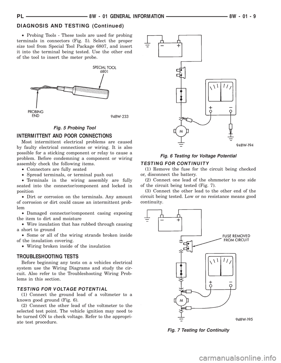
²Probing Tools - These tools are used for probing
terminals in connectors (Fig. 5). Select the proper
size tool from Special Tool Package 6807, and insert
it into the terminal being tested. Use the other end
of the tool to insert the meter probe.
INTERMITTENT AND POOR CONNECTIONS
Most intermittent electrical problems are caused
by faulty electrical connections or wiring. It is also
possible for a sticking component or relay to cause a
problem. Before condemning a component or wiring
assembly check the following items.
²Connectors are fully seated
²Spread terminals, or terminal push out
²Terminals in the wiring assembly are fully
seated into the connector/component and locked in
position
²Dirt or corrosion on the terminals. Any amount
of corrosion or dirt could cause an intermittent prob-
lem
²Damaged connector/component casing exposing
the item to dirt and moisture
²Wire insulation that has rubbed through causing
a short to ground
²Some or all of the wiring strands broken inside
of the insulation covering.
²Wiring broken inside of the insulation
TROUBLESHOOTING TESTS
Before beginning any tests on a vehicles electrical
system use the Wiring Diagrams and study the cir-
cuit. Also refer to the Troubleshooting Wiring Prob-
lems in this section.
TESTING FOR VOLTAGE POTENTIAL
(1) Connect the ground lead of a voltmeter to a
known good ground (Fig. 6).
(2) Connect the other lead of the voltmeter to the
selected test point. The vehicle ignition may need to
be turned ON to check voltage. Refer to the appropri-
ate test procedure.
TESTING FOR CONTINUITY
(1) Remove the fuse for the circuit being checked
or, disconnect the battery.
(2) Connect one lead of the ohmmeter to one side
of the circuit being tested (Fig. 7).
(3) Connect the other lead to the other end of the
circuit being tested. Low or no resistance means good
continuity.
Fig. 5 Probing Tool
Fig. 6 Testing for Voltage Potential
Fig. 7 Testing for Continuity
PL8W - 01 GENERAL INFORMATION 8W - 01 - 9
DIAGNOSIS AND TESTING (Continued)
Page 403 of 1200
TESTING FOR A SHORT TO GROUND
(1) Remove the fuse and disconnect all items
involved with the fuse.
(2) Connect a test light or a voltmeter across the
terminals of the fuse.
(3) Starting at the fuse block, wiggle the wiring
harness about six to eight inches apart and watch
the voltmeter/test lamp.
(4) If the voltmeter registers voltage or the test
lamp glows, there is a short to ground in that gen-
eral area of the wiring harness.
TESTING FOR A SHORT TO GROUND ON
FUSES POWERING SEVERAL LOADS
(1) Refer to the wiring diagrams and disconnect or
isolate all items on the suspected fused circuits.
(2) Replace the blown fuse.
(3) Supply power to the fuse by turning ON the
ignition switch or re-connecting the battery.
(4) Start connecting the items in the fuse circuit
one at a time. When the fuse blows the circuit with
the short to ground has been isolated.
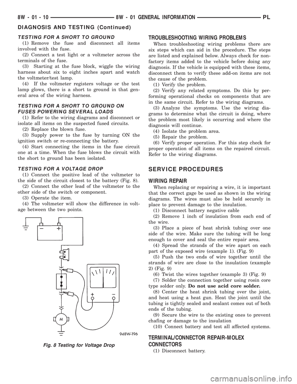
TESTING FOR A VOLTAGE DROP
(1) Connect the positive lead of the voltmeter to
the side of the circuit closest to the battery (Fig. 8).
(2) Connect the other lead of the voltmeter to the
other side of the switch or component.
(3) Operate the item.
(4) The voltmeter will show the difference in volt-
age between the two points.
TROUBLESHOOTING WIRING PROBLEMS
When troubleshooting wiring problems there are
six steps which can aid in the procedure. The steps
are listed and explained below. Always check for non-
factory items added to the vehicle before doing any
diagnosis. If the vehicle is equipped with these items,
disconnect them to verify these add-on items are not
the cause of the problem.
(1) Verify the problem.
(2) Verify any related symptoms. Do this by per-
forming operational checks on components that are
in the same circuit. Refer to the wiring diagrams.
(3) Analyze the symptoms. Use the wiring dia-
grams to determine what the circuit is doing, where
the problem most likely is occurring and where the
diagnosis will continue.
(4) Isolate the problem area.
(5) Repair the problem.
(6) Verify proper operation. For this step check for
proper operation of all items on the repaired circuit.
Refer to the wiring diagrams.
SERVICE PROCEDURES
WIRING REPAIR
When replacing or repairing a wire, it is important
that the correct gage be used as shown in the wiring
diagrams. The wires must also be held securely in
place to prevent damage to the insulation.
(1) Disconnect battery negative cable
(2) Remove 1 inch of insulation from each end of
the wire.
(3) Place a piece of heat shrink tubing over one
side of the wire. Make sure the tubing will be long
enough to cover and seal the entire repair area.
(4) Spread the strands of the wire apart on each
part of the exposed wire (example 1). (Fig. 9)
(5) Push the two ends of wire together until the
strands of wire are close to the insulation (example
2) (Fig. 9)
(6) Twist the wires together (example 3) (Fig. 9)
(7) Solder the connection together using rosin core
type solder only.Do not use acid core solder.
(8) Center the heat shrink tubing over the joint,
and heat using a heat gun. Heat the joint until the
tubing is tightly sealed and sealant comes out of both
ends of the tubing.
(9) Secure the wire to the existing ones to prevent
chafing or damage to the insulation
(10) Connect battery and test all affected systems.
TERMINAL/CONNECTOR REPAIR-MOLEX
CONNECTORS
(1) Disconnect battery.
Fig. 8 Testing for Voltage Drop
8W - 01 - 10 8W - 01 GENERAL INFORMATIONPL
DIAGNOSIS AND TESTING (Continued)
Page 694 of 1200
8W-95 SPLICE LOCATIONS
DESCRIPTION AND OPERATION
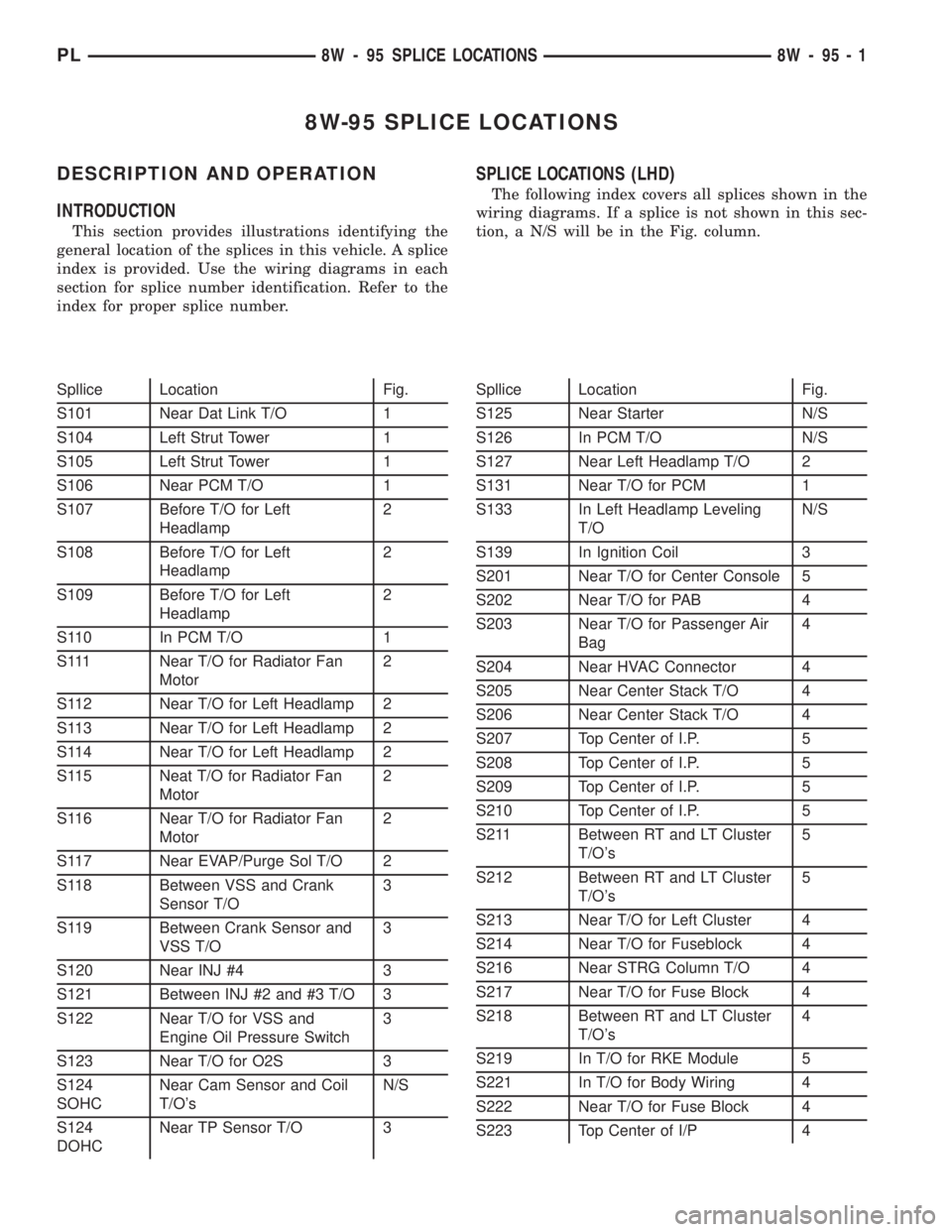
INTRODUCTION
This section provides illustrations identifying the
general location of the splices in this vehicle. A splice
index is provided. Use the wiring diagrams in each
section for splice number identification. Refer to the
index for proper splice number.
SPLICE LOCATIONS (LHD)
The following index covers all splices shown in the
wiring diagrams. If a splice is not shown in this sec-
tion, a N/S will be in the Fig. column.
Spllice Location Fig.
S101 Near Dat Link T/O 1
S104 Left Strut Tower 1
S105 Left Strut Tower 1
S106 Near PCM T/O 1
S107 Before T/O for Left
Headlamp2
S108 Before T/O for Left
Headlamp2
S109 Before T/O for Left
Headlamp2
S110 In PCM T/O 1
S111 Near T/O for Radiator Fan
Motor2
S112 Near T/O for Left Headlamp 2
S113 Near T/O for Left Headlamp 2
S114 Near T/O for Left Headlamp 2
S115 Neat T/O for Radiator Fan
Motor2
S116 Near T/O for Radiator Fan
Motor2
S117 Near EVAP/Purge Sol T/O 2
S118 Between VSS and Crank
Sensor T/O3
S119 Between Crank Sensor and
VSS T/O3
S120 Near INJ #4 3
S121 Between INJ #2 and #3 T/O 3
S122 Near T/O for VSS and
Engine Oil Pressure Switch3
S123 Near T/O for O2S 3
S124
SOHCNear Cam Sensor and Coil
T/O'sN/S
S124
DOHCNear TP Sensor T/O 3Spllice Location Fig.
S125 Near Starter N/S
S126 In PCM T/O N/S
S127 Near Left Headlamp T/O 2
S131 Near T/O for PCM 1
S133 In Left Headlamp Leveling
T/ON/S
S139 In Ignition Coil 3
S201 Near T/O for Center Console 5
S202 Near T/O for PAB 4
S203 Near T/O for Passenger Air
Bag4
S204 Near HVAC Connector 4
S205 Near Center Stack T/O 4
S206 Near Center Stack T/O 4
S207 Top Center of I.P. 5
S208 Top Center of I.P. 5
S209 Top Center of I.P. 5
S210 Top Center of I.P. 5
S211 Between RT and LT Cluster
T/O's5
S212 Between RT and LT Cluster
T/O's5
S213 Near T/O for Left Cluster 4
S214 Near T/O for Fuseblock 4
S216 Near STRG Column T/O 4
S217 Near T/O for Fuse Block 4
S218 Between RT and LT Cluster
T/O's4
S219 In T/O for RKE Module 5
S221 In T/O for Body Wiring 4
S222 Near T/O for Fuse Block 4
S223 Top Center of I/P 4
PL8W - 95 SPLICE LOCATIONS 8W - 95 - 1