1999 DODGE NEON height adjustment
[x] Cancel search: height adjustmentPage 12 of 1200
SUSPENSION
CONTENTS
page page
FRONT SUSPENSION..................... 10
REAR SUSPENSION...................... 39WHEEL ALIGNMENT....................... 1
WHEEL ALIGNMENT
INDEX
page page
DESCRIPTION AND OPERATION
COMPETITION PACKAGE ALIGNMENT........ 2
WHEEL ALIGNMENT GENERAL
INFORMATION......................... 1
DIAGNOSIS AND TESTING
PRE-ALIGNMENT VEHICLE INSPECTION...... 5
SUSPENSION AND STEERING DIAGNOSIS.... 3SERVICE PROCEDURES
WHEEL ALIGNMENT CHECK AND
ADJUSTMENT PROCEDURE.............. 5
SPECIFICATIONS
VEHICLE ALIGNMENT SPECIFICATIONS AT
CURB HEIGHT......................... 9
DESCRIPTION AND OPERATION
WHEEL ALIGNMENT GENERAL INFORMATION
Proper vehicle wheel alignment is the proper
adjustment of all interrelated front and rear suspen-
sion angles (Fig. 1). These angles are what affects
the handling and steering of the vehicle when it is in
motion.
The method of checking a vehicle's front and rear
wheel alignment will vary depending on the type and
manufacturer of the equipment being used. Instruc-
tions furnished by the manufacturer of the equip-
ment being used should always be followed to ensure
accuracy of the alignment, except alignment specifi-
cations recommended by Chrysler Corporation
MUST ALWAYSbe used.
CAUTION: Do not attempt to modify any suspen-
sion or steering components by heating or bending
of the component.Wheel alignment adjustments should be made in
the following sequence, to ensure that an accurate
alignment is performed.
(1) Rear Wheel Toe Adjustment within specifica-
tions for both total toe and thrust angle.
(2) Front Wheel Toe Adjustment within specifica-
tions for total toe.
(3)To eis measured in degrees or inches and is
the distance that the front edges of the tires are
closer (or farther apart) than the rear edges (Fig. 1).
See Front Wheel Drive Specifications for correct front
and rear wheel Toe specifications.
(4)Thrust Angleis defined as the average of the
Toe settings on each rear wheel. If this measurement
is out of specification, re-adjust rear wheel Toe so
that each wheel has 1/2 of the total Toe measure-
ment. When re-adjusting, do not exceed the total Toe
specification.
PLSUSPENSION 2 - 1
Page 16 of 1200
PRE-ALIGNMENT VEHICLE INSPECTION
CAUTION: If the front suspension crossmember
shows any sign of impact damage, the steering col-
umn to steering gear coupling must be inspected.
Refer to Group 19 Steering in this service manual
for the inspection procedure.
Before any attempt is made to change or correct
the wheel alignment factors, the following inspection
and necessary corrections must be made on those
parts which influence the steering of the vehicle.
(1) Be sure the fuel tank is full when the wheel
alignment specifications are checked and or adjusted.
A full tank of fuel weighs approximately 75 pounds,
if the fuel tank is not full this reduction in weight
will affect the curb height of the vehicle and the
alignment specifications.
(2) Alignment specifications of a vehicle can be the
most accurately checked and set when the passenger
compartment and trunk of the vehicle are vacant
with the exception of the spare tire. People, luggage,
and any other appreciable weight will adversely
affect the checking and setting of the camber specifi-
cation.
(3) Check and if required, inflate all of the tires to
the recommended air pressure. All tires must be of
the same size and in good condition and have approx-
imately the same tread wear.Note the type of
tread wear on the tire, this will aid in diagnos-
ing problems. Refer to Group 22 Tires And
Wheels in this service manual for the tire wear
diagnosis.
(4) Check the front tire and wheel assemblies for
radial runout.
(5) Before beginning the alignment process,
inspect all suspension component fasteners for loose-
ness and/or loss of specified torque.
(6) Inspect the lower front ball joints and all steer-
ing linkage for looseness and any signs of wear and
or damage.
(7) Inspect the tie rod ends for looseness and any
signs of wear and or damage.
(8) Inspect the rubber bushings on all suspension
components for signs of wear or deterioration. If any
bushings show signs of wear or deterioration they
should be replaced prior to aligning the vehicle.
SERVICE PROCEDURES
WHEEL ALIGNMENT CHECK AND ADJUSTMENT
PROCEDURE
CASTER CAMBER
Front and rear Caster and Camber settings on this
vehicle are determined at the time the vehicle isdesigned, by the location of the vehicle's suspension
components. This is called a Net Build vehicle and
results in no required adjustment of Caster and
Camber after vehicle is built or when servicing the
suspension components. Thus Caster and Camber are
not normally considered an adjustable specification
when performing an alignment on this vehicle.
Though Caster and Camber are not adjustable they
must be checked to ensure they meet vehicle specifi-
cations.
If front and or rear camber is found not to meet
the vehicle alignment specifications, it can be
adjusted using a Mopar Service Kit developed to
allow for camber adjustment. If a vehicle's front or
rear camber is found to be outside the specifications,
the vehicles suspension components should be
inspected for any signs of damage on bending.This
must be done before using the Mopar Service
Kit for setting camber to meet required specifi-
cation.
If a vehicles caster is not within manufacturers
alignment specifications, check for damaged suspen-
sion components or body parts. This type of damage
can cause component locations to move affecting
vehicle alignment.No adjustment can be made
for the Caster setting on this vehicle.
CAUTION: Do not attempt to adjust the vehicles
Caster or Camber by heating, bending or any other
modification of the suspension components.
(1) Correctly position vehicle on alignment rack
and install all required equipment on vehicle, per the
alignment equipment manufacturers specifications.
(2) Center the steering wheel and lock in place
using a steering wheel clamp.
NOTE: Prior to reading each alignment specifica-
tion, jounce the front and rear of the vehicle an
equal number of times. Induce jounce (rear first
then front) by grasping center of bumper and jounc-
ing each end of vehicle an equal number of times.
Bumper should always be released when vehicle is
at the bottom of the jounce cycle.
(3) Correctly jounce vehicle and read front and
rear alignment settings and compare to vehicle spec-
ifications for Camber, Caster and Toe. See Alignment
Specifications in this group of the service manual for
required specifications.If front and rear camber
readings are within required specifications pro-
ceed to step Step 3 in the Front And Rear Toe
Setting procedure. If Camber readings are not
within specifications refer to step Step 1 in the
following camber adjustment bolt package
installation procedure, for the front and rear
Camber adjustment procedure.
PLSUSPENSION 2 - 5
DIAGNOSIS AND TESTING (Continued)
Page 59 of 1200

(4) Install tension strut bushing, tension strut
retainer and nut on tension strut (Fig. 21).When
installing tension strut retainers, the retainers
must be installed on tension strut, with cupped
side of retainer facing away from bushing and
knuckle (Fig. 21).
(5) Position a large adjustable wrench on flat of
tension strut to keep it from turning, (Fig. 22) and
then torque tension strut nut to 95 N´m (70 ft. lbs.).
(6) On vehicles equipped with rear drum brakes,
install rear brake support plate assembly onto the
knuckle (Fig. 17). Install the 4 bolts (Fig. 17) attach-
ing rear brake support plate to rear knuckle. Torque
attaching bolts to 68 N´m (50 ft. lbs.).
(7) On vehicles equipped with rear disc brakes,
install the disc brake adapter on knuckle (Fig. 18)
Install the 4 bolts attaching the disc brake adapter to
knuckle (Fig. 18). Torque attaching bolts to 68 N´m
(50 ft. lbs.).(8) If vehicle is equipped with ABS brakes, install
speed sensor head into rear brake support plate or
disc brake adapter (Fig. 15). Tighten wheel speed
sensor mounting bolt to a torque of 7 N´m (60 in.
lbs.).
CAUTION: The hub/bearing retaining nut must be
tightened to but must not exceed its required
torque specification. The proper torque specifica-
tion of the retaining nut is critical to the life of the
hub bearing.
(9) Install rear hub and bearing assembly on
knuckle. Install hub and bearing assembly retaining
nut (Fig. 16), and torque to 217 N´m (160 ft. lbs).
(10) If vehicle is equipped with rear disc brakes,
install rear braking disc on hub. If vehicle is
equipped with rear drum brakes, install the brake
drum on hub.
(11) If vehicle is equipped with rear disc brakes,
install rear braking disc on hub. Carefully install
rear brake caliper over braking disc and install on
adapter. Tighten the caliper assembly to adapter
mounting bolts to 22 N´m (192 in. lbs.). Refer to Rear
Disc Brakes in Group 5 Brakes in this service man-
ual for required caliper installation procedure.
(12) Install wheel and tire assembly on vehicle.
Tighten the wheel mounting stud nuts in proper
sequence until all nuts are torqued to half specifica-
tion. Then repeat the tightening sequence to the full
specified torque of 135 N´m (100 ft. lbs.).
(13) Lower vehicle.
(14) With suspension supporting total weight of
vehicle, and lateral links at correct curb height,
torque both lateral link attaching bolts to 95 N´m (70
ft. lbs.).
(15) Check and reset rear wheel TOE to specifica-
tions if required. Refer to Front And Rear Toe Setting
Procedure in the Wheel Alignment Check And
Adjustment section in this group of the service man-
ual for the required Toe setting procedure.
LATERAL LINKS
The rear suspension lateral links (Fig. 23) are only
serviced as complete assemblies. The isolator bush-
ings used in the lateral links are not serviced as sep-
arate components. The rear lateral link assemblies
are unique, having different size bushings to accom-
modate the rear Toe adjustment cams. The rearward
lateral links, must be installed with small bushing
sleeve at knuckle and large bushing sleeve at rear
crossmember. This is required to accommodate the
rear Toe adjustment cam.
REMOVE
(1) Raise vehicle on jackstands or centered on a
frame contact type hoist. See Hoisting in the Lubri-
Fig. 21 Tension Strut Bushings Installed On Tension
Strut
Fig. 22 Torquing Tension Strut Nut
2 - 48 SUSPENSIONPL
REMOVAL AND INSTALLATION (Continued)
Page 61 of 1200
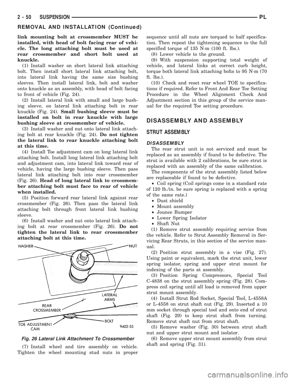
link mounting bolt at crossmember MUST be
installed, with head of bolt facing rear of vehi-
cle. The long attaching bolt must be used at
rear crossmember and short bolt used at
knuckle.
(1) Install washer on short lateral link attaching
bolt. Then install short lateral link attaching bolt,
into lateral link having the same size bushing
sleeves. Then install lateral link, bolt and washer
onto knuckle as an assembly, with head of bolt facing
to front of vehicle (Fig. 24).
(2) Install lateral link with small and large bush-
ing sleeve, on lateral link attaching bolt in rear
knuckle (Fig. 24).Small bushing sleeve must be
installed on bolt in rear knuckle with large
bushing sleeve at crossmember of vehicle.
(3) Install washer and nut onto lateral link attach-
ing bolt at rear knuckle (Fig. 24).Do not tighten
the lateral link to rear knuckle attaching bolt
at this time.
(4) Install Toe adjustment cam on long lateral link
attaching bolt. Install long lateral link attaching bolt
and adjustment cam, into lateral link toward rear of
vehicle, having the large bushing sleeve. Then pass
lateral link attaching bolt into rear crossmember
(Fig. 26).Head of long lateral link to crossmem-
ber attaching bolt must face to rear of vehicle
when installed.
(5) Position forward rear lateral link against rear
crossmember (Fig. 26). Then pass the lateral link
attaching bolt through front lateral link bushing
sleeve.
(6) Install washer and nut onto lateral link attach-
ing bolt at rear crossmember (Fig. 26).Do not
tighten the lateral link to rear crossmember
attaching bolt at this time.
(7) Install wheel and tire assembly on vehicle.
Tighten the wheel mounting stud nuts in propersequence until all nuts are torqued to half specifica-
tion. Then repeat the tightening sequence to the full
specified torque of 135 N´m (100 ft. lbs.).
(8) Lower vehicle to the ground.
(9) With suspension supporting total weight of
vehicle, and lateral links at correct curb height,
torque both lateral link attaching bolts to 95 N´m (70
ft. lbs.).
(10) Check and reset rear wheel TOE to specifica-
tions if required. Refer to Front And Rear Toe Setting
Procedure in the Wheel Alignment Check And
Adjustment section in this group of the service man-
ual for the required Toe setting procedure.
DISASSEMBLY AND ASSEMBLY
STRUT ASSEMBLY
DISASSEMBLY
The rear strut unit is not serviced and must be
replaced as an assembly if found to be defective. The
strut is available with 2 calibrations, be sure strut is
replaced with an assembly of the same calibration.
The components of the strut assembly listed below
are replaceable if found to be defective.
²Coil spring (Coil springs come in a standard rate
of 120 lb./in. be sure spring is replaced with a spring
of the same rate.)
²Dust shield
²Mount assembly
²Jounce Bumper
²Lower Spring Isolator
²Shaft Nut
(1) Remove strut assembly requiring service from
the vehicle. Refer to Strut Assembly Removal in Ser-
vicing Rear Struts, in this section of the service man-
ual.
(2) Position strut assembly in a vise (Fig. 27).
Using paint or equivalent, mark the strut unit, lower
spring isolator, spring and upper strut mount for
indexing of the parts at assembly.
(3) Position Spring Compressors, Special Tool
C-4838 on the strut assembly spring (Fig. 28). Com-
press coil spring until all load is removed from upper
strut mount assembly.
(4) Install Strut Rod Socket, Special Tool, L-4558A
or L-4558 on strut shaft nut (Fig. 29). Inserted a 10
mm socket through special tool and onto end of strut
shaft (Fig. 29) to keep strut shaft from turning.
Remove strut shaft nut from strut shaft.
(5) Remove washer (Fig. 30) between strut shaft
nut and upper strut mount and isolator.
(6) Remove upper strut mount assembly from strut
shaft and spring (Fig. 31).
Fig. 26 Lateral Link Attachment To Crossmember
2 - 50 SUSPENSIONPL
REMOVAL AND INSTALLATION (Continued)
Page 761 of 1200
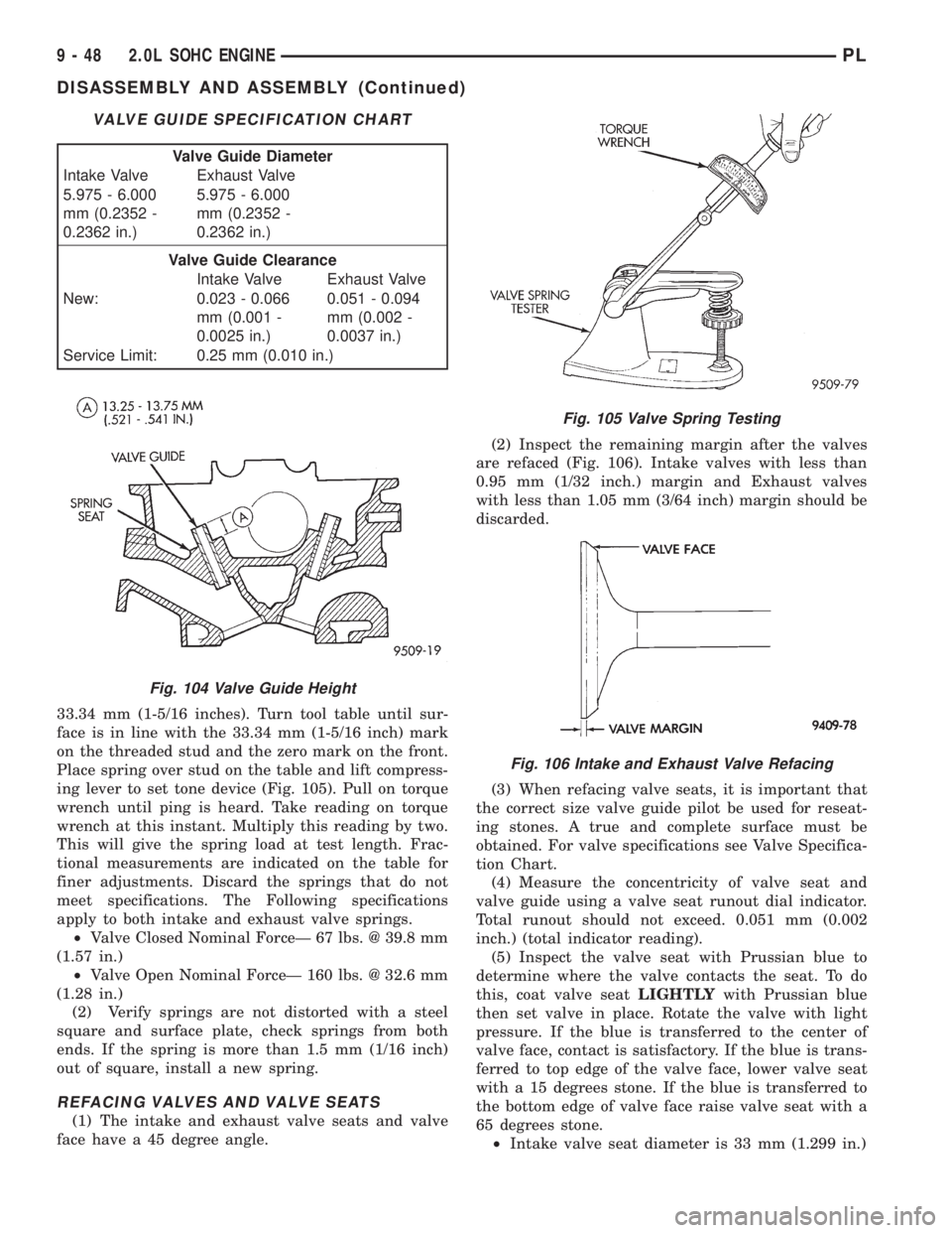
33.34 mm (1-5/16 inches). Turn tool table until sur-
face is in line with the 33.34 mm (1-5/16 inch) mark
on the threaded stud and the zero mark on the front.
Place spring over stud on the table and lift compress-
ing lever to set tone device (Fig. 105). Pull on torque
wrench until ping is heard. Take reading on torque
wrench at this instant. Multiply this reading by two.
This will give the spring load at test length. Frac-
tional measurements are indicated on the table for
finer adjustments. Discard the springs that do not
meet specifications. The Following specifications
apply to both intake and exhaust valve springs.
²Valve Closed Nominal ForceÐ 67 lbs. @ 39.8 mm
(1.57 in.)
²Valve Open Nominal ForceÐ 160 lbs. @ 32.6 mm
(1.28 in.)
(2) Verify springs are not distorted with a steel
square and surface plate, check springs from both
ends. If the spring is more than 1.5 mm (1/16 inch)
out of square, install a new spring.
REFACING VALVES AND VALVE SEATS
(1) The intake and exhaust valve seats and valve
face have a 45 degree angle.(2) Inspect the remaining margin after the valves
are refaced (Fig. 106). Intake valves with less than
0.95 mm (1/32 inch.) margin and Exhaust valves
with less than 1.05 mm (3/64 inch) margin should be
discarded.
(3) When refacing valve seats, it is important that
the correct size valve guide pilot be used for reseat-
ing stones. A true and complete surface must be
obtained. For valve specifications see Valve Specifica-
tion Chart.
(4) Measure the concentricity of valve seat and
valve guide using a valve seat runout dial indicator.
Total runout should not exceed. 0.051 mm (0.002
inch.) (total indicator reading).
(5) Inspect the valve seat with Prussian blue to
determine where the valve contacts the seat. To do
this, coat valve seatLIGHTLYwith Prussian blue
then set valve in place. Rotate the valve with light
pressure. If the blue is transferred to the center of
valve face, contact is satisfactory. If the blue is trans-
ferred to top edge of the valve face, lower valve seat
with a 15 degrees stone. If the blue is transferred to
the bottom edge of valve face raise valve seat with a
65 degrees stone.
²Intake valve seat diameter is 33 mm (1.299 in.)
VALVE GUIDE SPECIFICATION CHART
Valve Guide Diameter
Intake Valve Exhaust Valve
5.975 - 6.000
mm (0.2352 -
0.2362 in.)5.975 - 6.000
mm (0.2352 -
0.2362 in.)
Valve Guide Clearance
Intake Valve Exhaust Valve
New: 0.023 - 0.066
mm (0.001 -
0.0025 in.)0.051 - 0.094
mm (0.002 -
0.0037 in.)
Service Limit: 0.25 mm (0.010 in.)
Fig. 104 Valve Guide Height
Fig. 105 Valve Spring Testing
Fig. 106 Intake and Exhaust Valve Refacing
9 - 48 2.0L SOHC ENGINEPL
DISASSEMBLY AND ASSEMBLY (Continued)
Page 805 of 1200
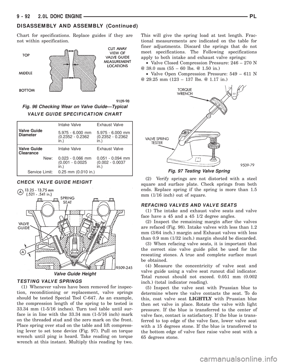
Chart for specifications. Replace guides if they are
not within specification.
CHECK VALVE GUIDE HEIGHT
TESTING VALVE SPRINGS
(1) Whenever valves have been removed for inspec-
tion, reconditioning or replacement, valve springs
should be tested Special Tool C-647. As an example,
the compression length of the spring to be tested is
33.34 mm (1-5/16 inches). Turn tool table until sur-
face is in line with the 33.34 mm (1-5/16 inch) mark
on the threaded stud and the zero mark on the front.
Place spring over stud on the table and lift compress-
ing lever to set tone device (Fig. 97). Pull on torque
wrench until ping is heard. Take reading on torque
wrench at this instant. Multiply this reading by two.This will give the spring load at test length. Frac-
tional measurements are indicated on the table for
finer adjustments. Discard the springs that do not
meet specifications. The Following specifications
apply to both intake and exhaust valve springs:
²Valve Closed Compression Pressure: 246 ± 270 N
@ 38.0 mm (55 ± 60 lbs. @ 1.50 in.)
²Valve Open Compression Pressure: 549 ± 611 N
@ 29.25 mm (123 ± 137 lbs. @ 1.17 in.)
(2) Verify springs are not distorted with a steel
square and surface plate. Check springs from both
ends. Replace spring if the spring is more than 1.5
mm (1/16 inch) out of square.
REFACING VALVES AND VALVE SEATS
(1) The intake and exhaust valve seats and valve
face have a 45 and a 45 1/2 degree angles.
(2) Inspect the remaining margin after the valves
are refaced (Fig. 98). Intake valves with less than 1.2
mm (3/64 inch.) margin and Exhaust valves with less
than 0.9 mm (1/32 inch.) margin should be discarded.
(3) When refacing valve seats, it is important that
the correct size valve guide pilot be used for the
reseating stones. A true and complete surface must
be obtained.
(4) Measure the concentricity of valve seat and
valve guide using a valve seat runout dial indicator.
Total runout should not exceed. 0.051 mm (0.002
inch.) (total indicator reading).
(5) Inspect the valve seat with Prussian blue to
determine where the valve contacts the seat. To do
this, coat valve seatLIGHTLYwith Prussian blue
then set valve in place. Rotate the valve with light
pressure. If the blue is transferred to the center of
valve face, contact is satisfactory. If the blue is trans-
ferred to top edge of the valve face, lower valve seat
with a 15 degrees stone. If the blue is transferred to
the bottom edge of valve face raise valve seat with a
65 degrees stone.
Fig. 96 Checking Wear on Valve GuideÐTypical
VALVE GUIDE SPECIFICATION CHART
Valve Guide
DiameterIntake Valve Exhaust Valve
5.975 - 6.000 mm
(0.2352 - 0.2362
in.)5.975 - 6.000 mm
(0.2352 - 0.2362
in.)
Valve Guide
ClearanceIntake Valve Exhaust Valve
New: 0.023 - 0.066 mm
(0.001 - 0.0025
in.)0.051 - 0.094 mm
(0.002 - 0.0037
in.)
Service Limit: 0.25 mm (0.010 in.)
Valve Guide Height
Fig. 97 Testing Valve Spring
9 - 92 2.0L DOHC ENGINEPL
DISASSEMBLY AND ASSEMBLY (Continued)
Page 1118 of 1200
(6) Connect wire connector to power window motor,
if so equipped.
(7) Install door speaker, if so equipped.
(8) Install door trim panel and water shield.
ADJUSTMENTS
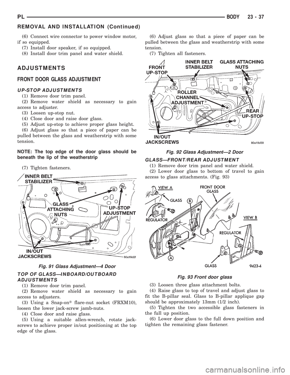
FRONT DOOR GLASS ADJUSTMENT
UP-STOP ADJUSTMENTS
(1) Remove door trim panel.
(2) Remove water shield as necessary to gain
access to adjuster.
(3) Loosen up-stop nut.
(4) Close door and raise door glass.
(5) Adjust up-stop to achieve proper glass height.
(6) Adjust glass so that a piece of paper can be
pulled between the glass and weatherstrip with some
tension.
NOTE: The top edge of the door glass should be
beneath the lip of the weatherstrip
(7) Tighten fasteners.
TOP OF GLASSÐINBOARD/OUTBOARD
ADJUSTMENTS
(1) Remove door trim panel.
(2) Remove water shield as necessary to gain
access to adjusters.
(3) Using a Snap-ontflare-nut socket (FRXM10),
loosen the lower jack-screw jamb-nuts.
(4) Close door and raise glass.
(5) Using a suitable allen-wrench, rotate jack-
screws to achieve proper in/out positioning at the top
edge of the glass.(6) Adjust glass so that a piece of paper can be
pulled between the glass and weatherstrip with some
tension.
(7) Tighten all fasteners.
GLASSÐFRONT/REAR ADJUSTMENT
(1) Remove door trim panel and water shield.
(2) Lower door glass to bottom of travel to gain
access to glass attachments. (Fig. 93)
(3) Loosen three glass attachment bolts.
(4) Raise glass to top of travel and adjust glass to
fit the B-pillar seal. Glass to B-pillar applique gap
should be approximately 13mm (1/2 inch).
(5) Tighten the two accessible glass fasteners in
the full up position.
(6) Lower door glass to the full down position and
tighten the remaining glass fastener.
Fig. 91 Glass AdjustmentÐ4 Door
Fig. 92 Glass AdjustmentÐ2 Door
Fig. 93 Front door glass
PLBODY 23 - 37
REMOVAL AND INSTALLATION (Continued)
Page 1119 of 1200
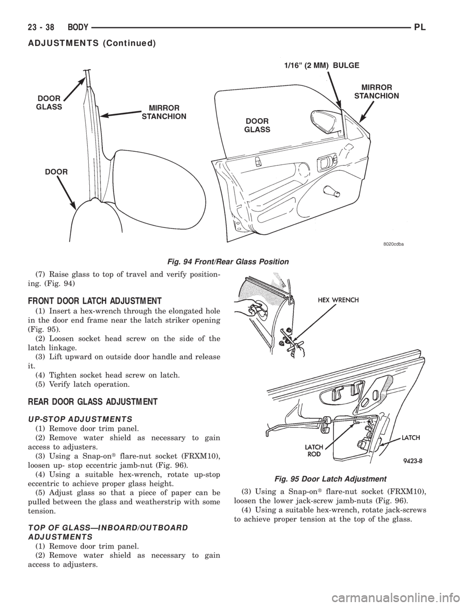
(7) Raise glass to top of travel and verify position-
ing. (Fig. 94)
FRONT DOOR LATCH ADJUSTMENT
(1) Insert a hex-wrench through the elongated hole
in the door end frame near the latch striker opening
(Fig. 95).
(2) Loosen socket head screw on the side of the
latch linkage.
(3) Lift upward on outside door handle and release
it.
(4) Tighten socket head screw on latch.
(5) Verify latch operation.
REAR DOOR GLASS ADJUSTMENT
UP-STOP ADJUSTMENTS
(1) Remove door trim panel.
(2) Remove water shield as necessary to gain
access to adjusters.
(3) Using a Snap-ontflare-nut socket (FRXM10),
loosen up- stop eccentric jamb-nut (Fig. 96).
(4) Using a suitable hex-wrench, rotate up-stop
eccentric to achieve proper glass height.
(5) Adjust glass so that a piece of paper can be
pulled between the glass and weatherstrip with some
tension.
TOP OF GLASSÐINBOARD/OUTBOARD
ADJUSTMENTS
(1) Remove door trim panel.
(2) Remove water shield as necessary to gain
access to adjusters.(3) Using a Snap-ontflare-nut socket (FRXM10),
loosen the lower jack-screw jamb-nuts (Fig. 96).
(4) Using a suitable hex-wrench, rotate jack-screws
to achieve proper tension at the top of the glass.
Fig. 94 Front/Rear Glass Position
Fig. 95 Door Latch Adjustment
23 - 38 BODYPL
ADJUSTMENTS (Continued)