1999 DODGE NEON change wheel
[x] Cancel search: change wheelPage 3 of 1200
ENGINE OIL
SAE VISCOSITY RATING INDICATES ENGINE OIL VISCOSITY
An SAE viscosity grade is used to specify the vis-
cosity of engine oil. SAE 30 specifies a single viscos-
ity engine oil. Engine oils also have multiple
viscosities. These are specified with a dual SAE vis-
cosity grade which indicates the cold-to-hot tempera-
ture viscosity range.
²SAE 30 = single grade engine oil.
²SAE 10W-30 = multiple grade engine oil.
API QUALITY CLASSIFICATION
The API Service Grade specifies the type of perfor-
mance the engine oil is intended to provide. The API
Service Grade specifications also apply to energy con-
serving engine oils.
Use engine oils that are API Service Certified.
5W-30 and 10W-30 MOPAR engine oils conform to
specifications.
Refer to Group 9, Engine for engine oil specifica-
tion.
GEAR LUBRICANTS
SAE ratings also apply to multiple grade gear
lubricants. In addition, API classification defines the
lubricants usage.
LUBRICANTS AND GREASES
Lubricating grease is rated for quality and usage
by the NLGI. All approved products have the NLGI
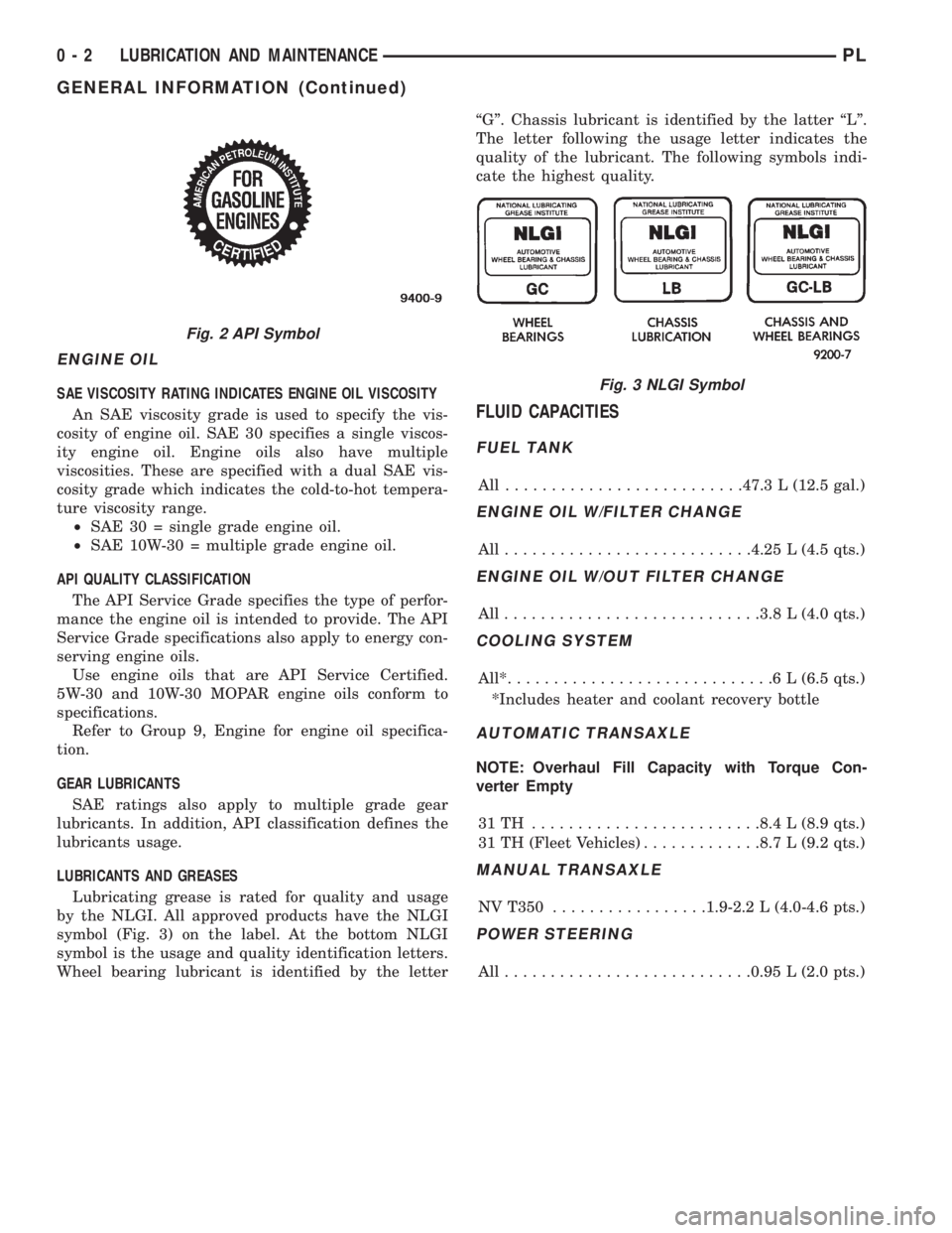
symbol (Fig. 3) on the label. At the bottom NLGI
symbol is the usage and quality identification letters.
Wheel bearing lubricant is identified by the letterªGº. Chassis lubricant is identified by the latter ªLº.
The letter following the usage letter indicates the
quality of the lubricant. The following symbols indi-
cate the highest quality.
FLUID CAPACITIES
FUEL TANK
All ..........................47.3 L (12.5 gal.)
ENGINE OIL W/FILTER CHANGE
All...........................4.25 L (4.5 qts.)
ENGINE OIL W/OUT FILTER CHANGE
All............................3.8 L (4.0 qts.)
COOLING SYSTEM
All*.............................6L(6.5 qts.)
*Includes heater and coolant recovery bottle
AUTOMATIC TRANSAXLE
NOTE: Overhaul Fill Capacity with Torque Con-
verter Empty
31TH .........................8.4 L (8.9 qts.)
31 TH (Fleet Vehicles).............8.7 L (9.2 qts.)
MANUAL TRANSAXLE
NV T350.................1.9-2.2 L (4.0-4.6 pts.)
POWER STEERING
All...........................0.95 L (2.0 pts.)
Fig. 2 API Symbol
Fig. 3 NLGI Symbol
0 - 2 LUBRICATION AND MAINTENANCEPL
GENERAL INFORMATION (Continued)
Page 13 of 1200
COMPETITION PACKAGE ALIGNMENT
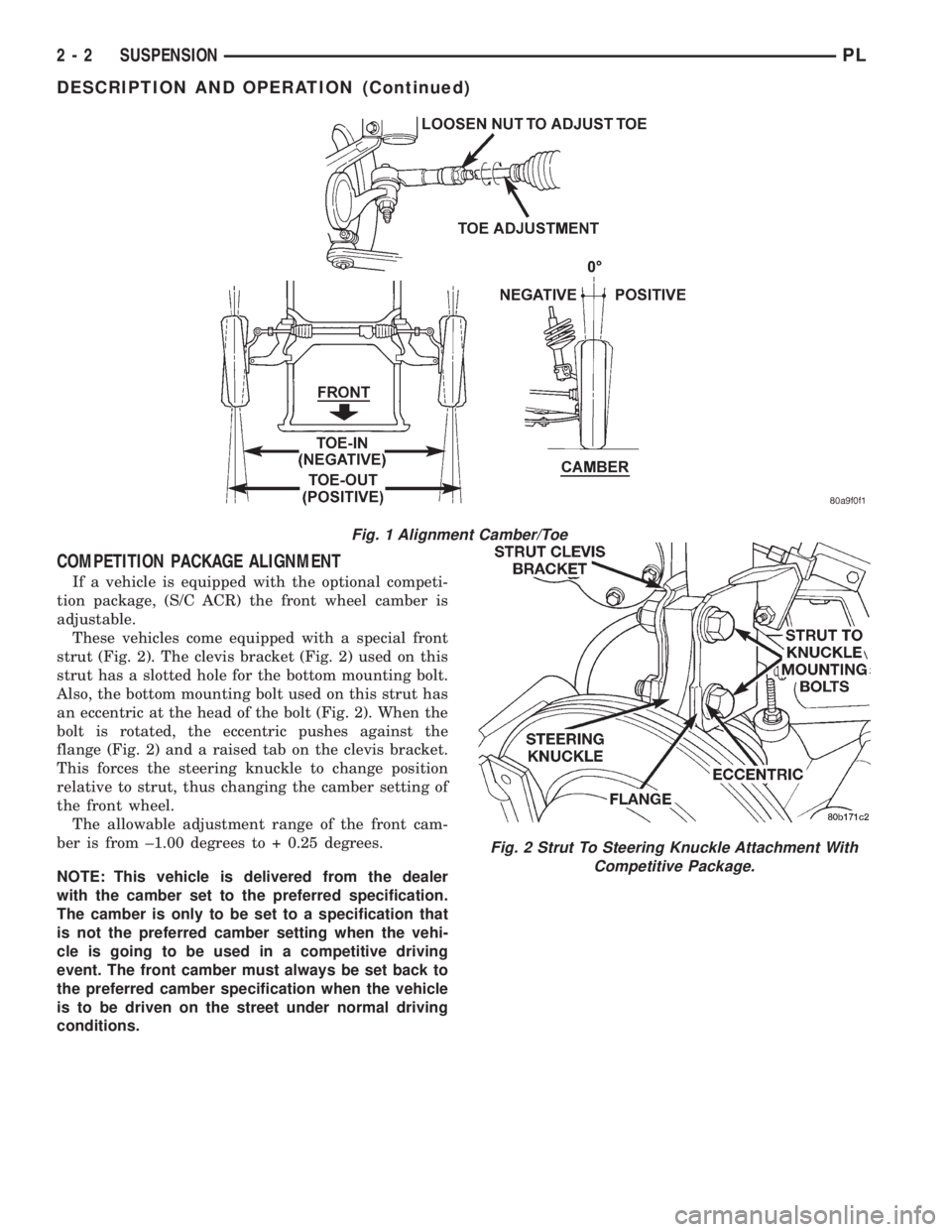
If a vehicle is equipped with the optional competi-
tion package, (S/C ACR) the front wheel camber is
adjustable.
These vehicles come equipped with a special front
strut (Fig. 2). The clevis bracket (Fig. 2) used on this
strut has a slotted hole for the bottom mounting bolt.
Also, the bottom mounting bolt used on this strut has
an eccentric at the head of the bolt (Fig. 2). When the
bolt is rotated, the eccentric pushes against the
flange (Fig. 2) and a raised tab on the clevis bracket.
This forces the steering knuckle to change position
relative to strut, thus changing the camber setting of
the front wheel.
The allowable adjustment range of the front cam-
ber is from ±1.00 degrees to + 0.25 degrees.
NOTE: This vehicle is delivered from the dealer
with the camber set to the preferred specification.
The camber is only to be set to a specification that
is not the preferred camber setting when the vehi-
cle is going to be used in a competitive driving
event. The front camber must always be set back to
the preferred camber specification when the vehicle
is to be driven on the street under normal driving
conditions.
Fig. 1 Alignment Camber/Toe
Fig. 2 Strut To Steering Knuckle Attachment With
Competitive Package.
2 - 2 SUSPENSIONPL
DESCRIPTION AND OPERATION (Continued)
Page 16 of 1200
PRE-ALIGNMENT VEHICLE INSPECTION
CAUTION: If the front suspension crossmember
shows any sign of impact damage, the steering col-
umn to steering gear coupling must be inspected.
Refer to Group 19 Steering in this service manual
for the inspection procedure.
Before any attempt is made to change or correct
the wheel alignment factors, the following inspection
and necessary corrections must be made on those
parts which influence the steering of the vehicle.
(1) Be sure the fuel tank is full when the wheel
alignment specifications are checked and or adjusted.
A full tank of fuel weighs approximately 75 pounds,
if the fuel tank is not full this reduction in weight
will affect the curb height of the vehicle and the
alignment specifications.
(2) Alignment specifications of a vehicle can be the
most accurately checked and set when the passenger
compartment and trunk of the vehicle are vacant
with the exception of the spare tire. People, luggage,
and any other appreciable weight will adversely
affect the checking and setting of the camber specifi-
cation.
(3) Check and if required, inflate all of the tires to
the recommended air pressure. All tires must be of
the same size and in good condition and have approx-
imately the same tread wear.Note the type of
tread wear on the tire, this will aid in diagnos-
ing problems. Refer to Group 22 Tires And
Wheels in this service manual for the tire wear
diagnosis.
(4) Check the front tire and wheel assemblies for
radial runout.
(5) Before beginning the alignment process,
inspect all suspension component fasteners for loose-
ness and/or loss of specified torque.
(6) Inspect the lower front ball joints and all steer-
ing linkage for looseness and any signs of wear and
or damage.
(7) Inspect the tie rod ends for looseness and any
signs of wear and or damage.
(8) Inspect the rubber bushings on all suspension
components for signs of wear or deterioration. If any
bushings show signs of wear or deterioration they
should be replaced prior to aligning the vehicle.
SERVICE PROCEDURES
WHEEL ALIGNMENT CHECK AND ADJUSTMENT
PROCEDURE
CASTER CAMBER
Front and rear Caster and Camber settings on this
vehicle are determined at the time the vehicle isdesigned, by the location of the vehicle's suspension
components. This is called a Net Build vehicle and
results in no required adjustment of Caster and
Camber after vehicle is built or when servicing the
suspension components. Thus Caster and Camber are
not normally considered an adjustable specification
when performing an alignment on this vehicle.
Though Caster and Camber are not adjustable they
must be checked to ensure they meet vehicle specifi-
cations.
If front and or rear camber is found not to meet
the vehicle alignment specifications, it can be
adjusted using a Mopar Service Kit developed to
allow for camber adjustment. If a vehicle's front or
rear camber is found to be outside the specifications,
the vehicles suspension components should be
inspected for any signs of damage on bending.This
must be done before using the Mopar Service
Kit for setting camber to meet required specifi-
cation.
If a vehicles caster is not within manufacturers
alignment specifications, check for damaged suspen-
sion components or body parts. This type of damage
can cause component locations to move affecting
vehicle alignment.No adjustment can be made
for the Caster setting on this vehicle.
CAUTION: Do not attempt to adjust the vehicles
Caster or Camber by heating, bending or any other
modification of the suspension components.
(1) Correctly position vehicle on alignment rack
and install all required equipment on vehicle, per the
alignment equipment manufacturers specifications.
(2) Center the steering wheel and lock in place
using a steering wheel clamp.
NOTE: Prior to reading each alignment specifica-
tion, jounce the front and rear of the vehicle an
equal number of times. Induce jounce (rear first
then front) by grasping center of bumper and jounc-
ing each end of vehicle an equal number of times.
Bumper should always be released when vehicle is
at the bottom of the jounce cycle.
(3) Correctly jounce vehicle and read front and
rear alignment settings and compare to vehicle spec-
ifications for Camber, Caster and Toe. See Alignment
Specifications in this group of the service manual for
required specifications.If front and rear camber
readings are within required specifications pro-
ceed to step Step 3 in the Front And Rear Toe
Setting procedure. If Camber readings are not
within specifications refer to step Step 1 in the
following camber adjustment bolt package
installation procedure, for the front and rear
Camber adjustment procedure.
PLSUSPENSION 2 - 5
DIAGNOSIS AND TESTING (Continued)
Page 18 of 1200
COMPETITION PACKAGE ALIGNMENT PROCEDURE
If a vehicle is equipped with the optional competi-
tion package, (S/C ACR) the front wheel camber is
adjustable.
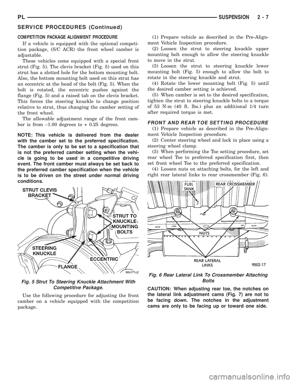
These vehicles come equipped with a special front
strut (Fig. 5). The clevis bracket (Fig. 5) used on this
strut has a slotted hole for the bottom mounting bolt.
Also, the bottom mounting bolt used on this strut has
an eccentric at the head of the bolt (Fig. 5). When the
bolt is rotated, the eccentric pushes against the
flange (Fig. 5) and a raised tab on the clevis bracket.
This forces the steering knuckle to change position
relative to strut, thus changing the camber setting of
the front wheel.
The allowable adjustment range of the front cam-
ber is from ±1.00 degrees to + 0.25 degrees.
NOTE: This vehicle is delivered from the dealer
with the camber set to the preferred specification.
The camber is only to be set to a specification that
is not the preferred camber setting when the vehi-
cle is going to be used in a competitive driving
event. The front camber must always be set back to
the preferred camber specification when the vehicle
is to be driven on the street under normal driving
conditions.
Use the following procedure for adjusting the front
camber on a vehicle equipped with the competition
package.(1) Prepare vehicle as described in the Pre-Align-
ment Vehicle Inspection procedure.
(2) Loosen the strut to steering knuckle upper
mounting bolt enough to allow the steering knuckle
to move in the strut.
(3) Loosen the strut to steering knuckle lower
mounting bolt (Fig. 5) enough to allow the bolt to
rotate in the steering knuckle and strut.
(4) Rotate the lower mounting bolt (Fig. 5) until
the desired camber setting is achieved.
(5) When camber is set to the desired specification,
tighten the strut to steering knuckle bolts to a torque
of 53 N´m (40 ft. lbs.) plus an additional 1/4 turn
after required torque is met.
FRONT AND REAR TOE SETTING PROCEDURE
(1) Prepare vehicle as described in the Pre-Align-
ment Vehicle Inspection procedure.
(2) Center steering wheel and lock in place using a
steering wheel clamp.
(3) When performing the Toe setting procedure, set
rear wheel Toe to preferred specification first, then
set front wheel Toe to the preferred specification.
(4) Loosen nuts on attaching bolts, for the left and
right rear lateral links to rear crossmember (Fig. 6).
CAUTION: When adjusting rear toe, the notches on
the lateral link adjustment cams (Fig. 7) are not to
be facing down. The notches in the adjustment
cams are only to be facing up or toward one side.
Fig. 5 Strut To Steering Knuckle Attachment With
Competitive Package.
Fig. 6 Rear Lateral Link To Crossmember Attaching
Bolts
PLSUSPENSION 2 - 7
SERVICE PROCEDURES (Continued)
Page 128 of 1200
(9) Position master cylinder on studs of power
brake unit, aligning push rod on power brake vac-
uum booster with master cylinder push rod.
(10) Install the 2 master cylinder mounting nuts
(Fig. 117) and torque to 28 N´m (250 in. lbs.) torque.
(11) Connect brake tubes to master cylinder pri-
mary and secondary ports (Fig. 115) and (Fig. 116).
Torque all tube nuts to 17 N´m (145 in. lbs.) torque.
(12) Reconnect wiring connector to fluid level sen-
sor.
(13) Adjust stop lamp switch as necessary.
(14) Bleed brake system.
CHASSIS TUBES AND HOSES
Always use Mopar replacement brake hose assem-
blies to ensure quality, correct length and superior
fatigue life. Care should be taken to make sure that
the tube and hose mating surfaces are clean and free
from nicks and burrs.Hose assemblies for each
brake are unique and not interchangeable.
Use new copper seal washers on all connections
using Banjo Bolts and tighten all fittings to their
specified torques.
The flexible front hydraulic brake hose should
always be installed on the vehicle by first attaching
the Banjo connector to the caliper assembly. Then
bolt the intermediate hose bracket to the strut
assembly allowing the bracket to position the hose to
prevent twisting. Attach the hose to brake tubing,
before attaching to front frame rail. Then tighten all
brake line fittings to specified torque.
On vehicles equipped with rear drum brakes,
install rear brake hoses first to wheel cylinders and
rear struts and then attach hose bracket to body. On
vehicles equipped with rear disc brakes, attach brake
hoses to calipers and struts first and then attach
brake hose bracket to body. Following this procedure
will reduce potential for twisting brake during instal-
lation procedure.
Only double wall 4.75mm (3/16 in.) steel brake line
tubing, with Al- Rich/ZN-AL alloy coating should be
used for replacement. Care must be taken when
replacing brake tubing, to be sure the proper bending
and flaring tools and procedures are used to avoid
kinking. Do not route the tubes against sharp edges,
moving components or into hot areas. All tubes
should be properly attached with recommended
retaining clips.
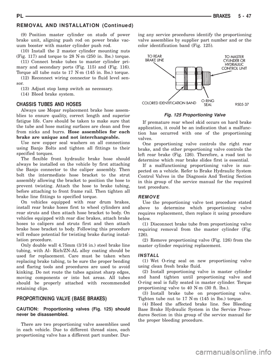
PROPORTIONING VALVE (BASE BRAKES)
CAUTION: Proportioning valves (Fig. 125) should
never be disassembled.
There are two proportioning valve assemblies used
in each vehicle. Due to different thread sizes, each
proportioning valve has a different part number. Dur-ing any service procedures identify the proportioning
valve assemblies by supplier part number and or the
color identification band (Fig. 125).
If premature rear wheel skid occurs on hard brake
application, it could be an indication that a malfunc-
tion has occurred with one of the proportioning
valves.
One proportioning valve controls the right rear
brake, and the other proportioning valve controls the
left rear brake (Fig. 126). Therefore, a road test to
determine which rear brake slides first is essential.
If a malfunctioning proportioning valve is sus-
pected on a vehicle. Refer to Brake Hydraulic System
Control Valves in the Diagnosis And Testing Section
in this group of the service manual for the required
test procedure.
REMOVE
Use the proportioning valve test procedure stated
above to determine which proportioning valve
requires replacement, then replace it using procedure
below.
(1) Disconnect brake tube from proportioning valve
requiring removal from the master cylinder (Fig.
126).
(2) Remove proportioning valve (Fig. 126) from the
master cylinder requiring replacement.
INSTALL
(1) Wet O-ring seal on new proportioning valve
using clean fresh brake fluid.
(2) Install proportioning valve in master cylinder
and hand tighten until proportioning valve and
O-ring seal is fully seated in master cylinder. Torque
proportioning valve to 40 N´m (30 ft. lbs.).
(3) Install brake tube on proportioning valve.
Tighten tube nut to 17 N´m (145 in lbs.) torque.
(4) Bleed the affected brake line. See Bleeding
Base Brake Hydraulic System in the Service Proce-
dures Section in this group of the service manual for
the proper bleeding procedure.
Fig. 125 Proportioning Valve
PLBRAKES 5 - 47
REMOVAL AND INSTALLATION (Continued)
Page 146 of 1200
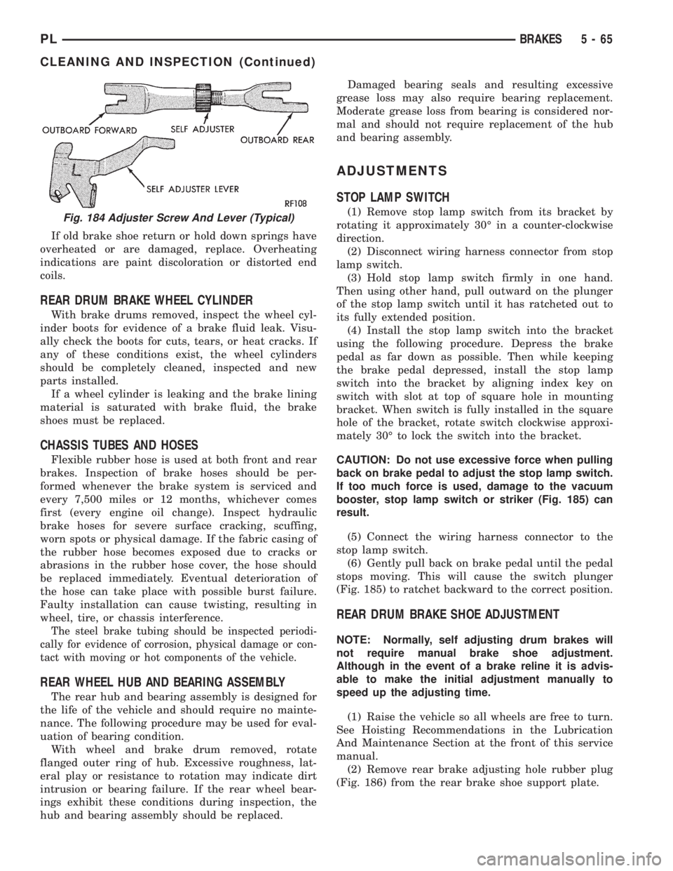
If old brake shoe return or hold down springs have
overheated or are damaged, replace. Overheating
indications are paint discoloration or distorted end
coils.
REAR DRUM BRAKE WHEEL CYLINDER
With brake drums removed, inspect the wheel cyl-
inder boots for evidence of a brake fluid leak. Visu-
ally check the boots for cuts, tears, or heat cracks. If
any of these conditions exist, the wheel cylinders
should be completely cleaned, inspected and new
parts installed.
If a wheel cylinder is leaking and the brake lining
material is saturated with brake fluid, the brake
shoes must be replaced.
CHASSIS TUBES AND HOSES
Flexible rubber hose is used at both front and rear
brakes. Inspection of brake hoses should be per-
formed whenever the brake system is serviced and
every 7,500 miles or 12 months, whichever comes
first (every engine oil change). Inspect hydraulic
brake hoses for severe surface cracking, scuffing,
worn spots or physical damage. If the fabric casing of
the rubber hose becomes exposed due to cracks or
abrasions in the rubber hose cover, the hose should
be replaced immediately. Eventual deterioration of
the hose can take place with possible burst failure.
Faulty installation can cause twisting, resulting in
wheel, tire, or chassis interference.
The steel brake tubing should be inspected periodi-
cally for evidence of corrosion, physical damage or con-
tact with moving or hot components of the vehicle.
REAR WHEEL HUB AND BEARING ASSEMBLY
The rear hub and bearing assembly is designed for
the life of the vehicle and should require no mainte-
nance. The following procedure may be used for eval-
uation of bearing condition.
With wheel and brake drum removed, rotate
flanged outer ring of hub. Excessive roughness, lat-
eral play or resistance to rotation may indicate dirt
intrusion or bearing failure. If the rear wheel bear-
ings exhibit these conditions during inspection, the
hub and bearing assembly should be replaced.Damaged bearing seals and resulting excessive
grease loss may also require bearing replacement.
Moderate grease loss from bearing is considered nor-
mal and should not require replacement of the hub
and bearing assembly.
ADJUSTMENTS
STOP LAMP SWITCH
(1) Remove stop lamp switch from its bracket by
rotating it approximately 30É in a counter-clockwise
direction.
(2) Disconnect wiring harness connector from stop
lamp switch.
(3) Hold stop lamp switch firmly in one hand.
Then using other hand, pull outward on the plunger
of the stop lamp switch until it has ratcheted out to
its fully extended position.
(4) Install the stop lamp switch into the bracket
using the following procedure. Depress the brake
pedal as far down as possible. Then while keeping
the brake pedal depressed, install the stop lamp
switch into the bracket by aligning index key on
switch with slot at top of square hole in mounting
bracket. When switch is fully installed in the square
hole of the bracket, rotate switch clockwise approxi-
mately 30É to lock the switch into the bracket.
CAUTION: Do not use excessive force when pulling
back on brake pedal to adjust the stop lamp switch.
If too much force is used, damage to the vacuum
booster, stop lamp switch or striker (Fig. 185) can
result.
(5) Connect the wiring harness connector to the
stop lamp switch.
(6) Gently pull back on brake pedal until the pedal
stops moving. This will cause the switch plunger
(Fig. 185) to ratchet backward to the correct position.
REAR DRUM BRAKE SHOE ADJUSTMENT
NOTE: Normally, self adjusting drum brakes will
not require manual brake shoe adjustment.
Although in the event of a brake reline it is advis-
able to make the initial adjustment manually to
speed up the adjusting time.
(1) Raise the vehicle so all wheels are free to turn.
See Hoisting Recommendations in the Lubrication
And Maintenance Section at the front of this service
manual.
(2) Remove rear brake adjusting hole rubber plug
(Fig. 186) from the rear brake shoe support plate.
Fig. 184 Adjuster Screw And Lever (Typical)
PLBRAKES 5 - 65
CLEANING AND INSPECTION (Continued)
Page 310 of 1200
TURN SIGNAL AND FLASHERS
CONTENTS
page page
GENERAL INFORMATION
INTRODUCTION......................... 1
DESCRIPTION AND OPERATION
COMBINATION FLASHER.................. 1
HAZARD WARNING SYSTEM............... 1DIAGNOSIS AND TESTING
MULTI-FUNCTION SWITCH................ 2
MULTI-FUNCTION SWITCH TEST............ 2
REMOVAL AND INSTALLATION
MULTI-FUNCTION SWITCH................ 4
GENERAL INFORMATION
INTRODUCTION
WARNING: ON VEHICLES EQUIPPED WITH AIR-
BAG, SEE GROUP 8M, RESTRAINT SYSTEMS FOR
AIRBAG REMOVAL PROCEDURES.
The turn signals are part of the multi-function
switch. Which contains:
²Electrical circuitry for turn signals
²Hazard warning switch
²Headlamp beam select switch
²Headlamp optical horn
The integrated switch assembly is mounted to the
left hand side of the steering column. When the
driver wishes to signal his intentions to change direc-
tion of travel, he moves the lever upward to cause
the right signals to flash and downward to cause the
left signals to flash. After completion of a turn the
system is deactivated automatically. As the steering
wheel returns to the straight ahead position, a can-
celing cam molded to the clockspring mechanism
comes in contact with the cancel actuator on the turn
signal multi-function switch assembly. The cam lobe,
pushing on the cancel actuator, returns the switch to
the off position.
If only momentary signaling such as indication of a
lane change is desired, the switch is actuated to a
left or right intermediate detent position. In this
position the signal lamps flash as described above,
but the switch returns to the OFF position as soon as
the lever is released.
When the system is activated, one of two indicator
lamps mounted in the instrument cluster flashes in
unison with the turn signal lamps, indicating to the
driver that the system is operating.
DESCRIPTION AND OPERATION
HAZARD WARNING SYSTEM
The hazard warning system is actuated by a slide
button located on the top of the steering column
between the steering wheel and the instrument
panel. The hazard switch is identified with a double
triangle on front of the button.
COMBINATION FLASHER
The turn signal flasher and the hazard warning
flasher are combined into one unit called a combina-
tion flasher (combo-flasher). The combo- flasher con-
trols the flashing of the hazard warning system and
the turn signal system. An inoperative bulb or incom-
plete turn signal circuit will cause the flasher rate to
double.
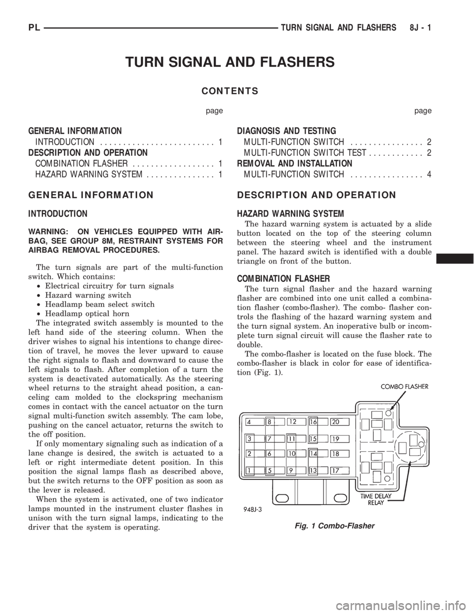
The combo-flasher is located on the fuse block. The
combo-flasher is black in color for ease of identifica-
tion (Fig. 1).
Fig. 1 Combo-Flasher
PLTURN SIGNAL AND FLASHERS 8J - 1
Page 314 of 1200
WINDSHIELD WIPERS AND WASHERS
CONTENTS
page page
WINDSHIELD WASHER SYSTEM............. 8WINDSHIELD WIPERS..................... 1
WINDSHIELD WIPERS
INDEX
page page
GENERAL INFORMATION
INTRODUCTION......................... 1
DESCRIPTION AND OPERATION
WIPER BLADES.......................... 1
DIAGNOSIS AND TESTING
WINDSHIELD WIPER CONDITION............ 2
WIPER MOTOR.......................... 3
WIPER SWITCH.......................... 5
REMOVAL AND INSTALLATION
WIPER ARM............................. 5WIPER BLADE ELEMENT.................. 5
WIPER BLADE........................... 5
WIPER LINKAGE......................... 6
WIPER MODULE......................... 6
WIPER MOTOR.......................... 6
WIPER SWITCH.......................... 6
CLEANING AND INSPECTION
WIPER BLADES.......................... 6
ADJUSTMENTS
WIPER ARM ADJUSTMENT................. 7
GENERAL INFORMATION
INTRODUCTION
WARNING: VEHICLES ARE EQUIPPED WITH AN
AIRBAG, REFER TO GROUP 8M, RESTRAINT SYS-
TEMS FOR STEERING WHEEL OR COLUMN SER-
VICE PROCEDURES.
The windshield wipers will only operate with the
ignition switch in the ACCESSORY or IGNITION
RUN position. The wiper circuit is protect against
over loads by a fuse in the fuse block and a circuit
breaker within the wiper motor. This protects the cir-
cuitry of the wiper system and the vehicle.
The wiper motor has permanent magnet fields.
The intermittent wiper system, in addition to low
and high speed, has a delay mode and a pulse wipe
mode. The delay mode has a range of 1 to 15 seconds.
Pulse wipe is accomplished by momentarily moving
the stalk lever into the WASH position while the
wiper switch is in either OFF or DELAY position.
The wiper blades then sweep once or twice and
return to the previous wiper switch mode, OFF or
DELAY.The intermittent wiper function is integral to the
wiper switch. All electronics and relay are inside the
switch assembly.
The wiper system completes the wipe cycle when
the switch is turned OFF. The blades park in the
lowest portion of the wipe pattern.
DESCRIPTION AND OPERATION
WIPER BLADES
Wiper blades, exposed to the weather for a long
period of time, tend to lose their wiping effectiveness.
Periodic cleaning of the wiper blade is suggested to
remove the accumulation of salt and road film. The
wiper blades, arms, and windshield should be
cleaned with a sponge or cloth and a mild detergent
or nonabrasive cleaner. If the blades continue to
streak or smear, they should be replaced. The right
and left wipers are different blade lengths. The
driver side length is 525 mm and the passenger side
length is 450 mm. The blades should not be inter-
changed.
PLWINDSHIELD WIPERS AND WASHERS 8K - 1