1999 DODGE NEON automatic transmission
[x] Cancel search: automatic transmissionPage 4 of 1200
MAINTENANCE SCHEDULES
INDEX
page page
GENERAL INFORMATION
INTRODUCTION......................... 3
SCHEDULE ± A.......................... 3SCHEDULE ± B.......................... 4
UNSCHEDULED INSPECTION............... 3
GENERAL INFORMATION
INTRODUCTION
Service and maintenance procedures for compo-
nents and systems listed in Schedule ± A or B can be
found by using the Group Tab Locator index at the
front of this manual. If it is not clear which group
contains the information needed, refer to the index at
the back of this manual.
There are two maintenance schedules that show
proper service based on the conditions that the vehi-
cle is subjected to. Use the schedule that best
describes these conditions.
Schedule ±A, lists maintenance recommended for
vehicles used for general transportation.
Schedule ±B, lists maintenance recommended for
vehicles used under the following conditions:
²Frequent short trip driving less than 5 miles (8
km)
²Frequent driving in dusty conditions
²Frequent trailer towing
²Extensive idling
²More than 50% of your driving is at sustained
high speeds during hot weather, above 90ÉF (32ÉC)
Where time and mileage are listed, follow the
interval that occurs first.
EMISSION CONTROL SYSTEM MAINTENANCE
The scheduled emission maintenance listed inbold
typeon the Maintenance Schedules, must be done at
the mileage specified to assure the continued proper
functioning of the emission control system. These,
and all other maintenance services included in this
manual, should be done to provide the best vehicle
performance and reliability. More frequent mainte-
nance may be needed for vehicles in severe operating
conditions such as dusty areas and very short trip
driving.
UNSCHEDULED INSPECTION
At Each Stop For Fuel
²Check engine oil level, add as required.
²Check windshield washer solvent and add if
required.
Once A Month
²Check tire pressure and look for unusual wear
or damage.
²Inspect battery, clean, and tighten terminals as
required.
²Check fluid levels of coolant reservoir, power
steering and automatic transmission and add as
required.
²Check all lights and all other electrical items for
correct operation.
At Each Oil Change
²Inspect exhaust system.
²Inspect brake hoses.
²Inspect the CV joints and front suspension com-
ponents.
²Rotate the tires at each oil change interval
shown on Schedule ± A (7,500 miles) or every other
interval shown on schedule ± B (6,000 miles).
²Check coolant level, hoses and clamps.
²Check the manual transaxle fluid level.
²If the mileage is less than 7,500 miles (12 000
km) yearly, replace the engine oil filter at each oil
change.
SCHEDULE ± A
7,500 Miles (12 000 km) or at 6 months
²Change engine oil.
15,000 Miles (24 000 km) or at 12 months
²Change engine oil.
²Replace engine oil filter.
²Adjust drive belt tension.
22,500 Miles (36 000 km) or at 18 months
²Change engine oil.
²Inspect the front brake pads and rear brake lin-
ings.
30,000 Miles (48 000 km) or at 24 months
²Change engine oil.
²Replace engine oil filter.
²Lubricate front suspension ball joints.
²Adjust drive belt tension.
PLLUBRICATION AND MAINTENANCE 0 - 3
Page 5 of 1200

²Replace air cleaner element.
²Replace spark plugs.
²Change automatic transmission fluid.
37,500 Miles (60 000 km) or at 30 months
²Change engine oil.
45,000 Miles (72 000 km) or at 36 months
²Change engine oil.
²Replace engine oil filter.
²Inspect front brake pads and rear brake linings.
²Adjust drive belt tension.
²Flush and replace engine coolant at 36 months,
regardless of mileage.
52,500 Miles (84 000 km) or at 42 months
²Change engine oil.
²Flush and replace engine coolant if not done at
36 months.
60,000 Miles (96 000 km) or at 48 months
²Change engine oil.
²Replace engine oil filter.
²Check and replace, if necessary***, the PCV
valve.**
²Lubricate front suspension upper ball joints.
²Replace drive belts.
²Replace air cleaner element.
²Replace ignition cables.
²Replace spark plugs.
²Change automatic transmission fluid.
67,500 Miles (108 000 km) or at 54 months
²Change engine oil.
²Inspect front brake pads and rear brake linings.
75,000 Miles (120 000 km) or at 60 months
²Change engine oil.
²Replace engine oil filter.
²Adjust drive belt tension.
²Flush and replace engine coolant if it has been
30,000 miles (48 000 km) or 24 months since last
change.
82,500 Miles (132 000 km) or at 66 months
²Change engine oil.
²Flush and replace engine coolant if it has been
30,000 miles (48 000 km) or 24 months since last
change.
90,000 Miles (144 000 km) or at 72 months
²Change engine oil.
²Replace engine oil filter.
²Check and replace, if necessary***, the PCV
valve.**
²Lubricate front suspension upper ball joints.
²Inspect front brake pads and rear brake linings.²Adjust drive belt tension.
²Replace air cleaner air cleaner element.
²Replace spark plugs.
²Change automatic transmission fluid.
97,500 Miles (156 000 km) or at 78 months
²Change engine oil.
105,000 Miles (168 000 km)
²Change engine oil.
²Replace engine oil filter.
²Replace engine timing belt
²Adjust drive belt tension.
SCHEDULE ± B
NOTE: * Follow this schedule if you usually operate
your vehicle under one or more of the following
conditions. Change the automatic transmission
fluid and filter every 15,000 miles (24 000 km) if you
usually operate your vehicle under one of the con-
ditions marked with an *.
3,000 Miles (5 000 km)
²Change engine oil
6,000 Miles (10 000 km)
²Change engine oil
²Replace engine oil filter.
9,000 Miles (14 000 km)
²Change engine oil
²Inspect front brake pads and rear brake lining.
12,000 Miles (19 000 km)
²Change engine oil
²Replace engine oil filter.
15,000 Miles (24 000 km)
²Change engine oil
²Adjust drive belt tension.
²Inspect and replace, if required, the air
cleaner element.
²Change automatic transaxle fluid and filter.
Adjust the bands.*
18,000 Miles (29 000 km)
²Change engine oil
²Replace engine oil filter.
²Inspect front brake pads and rear brake linings.
21,000 Miles (34 000 km)
²Change engine oil
0 - 4 LUBRICATION AND MAINTENANCEPL
GENERAL INFORMATION (Continued)
Page 6 of 1200

24,000 Miles (38 000 km)
²Change engine oil
²Replace engine oil filter.
27,000 Miles (43 000 km)
²Change engine oil
²Inspect front brake pads and rear brake linings.
30,000 Miles (48 000 km)
²Change engine oil
²Replace engine oil filter.
²Check and replace, if necessary, the PCV
valve.**
²Lubricate front suspension upper ball joints.
²Adjust drive belt tension.
²Replace air cleaner element.
²Replace spark plugs.
²Change automatic transmission fluid and filter.
Adjust the bands.*
33,000 Miles (53 000 km)
²Change engine oil.
36,000 Miles (58 000 km)
²Change engine oil.
²Replace engine oil filter.
²Flush and replace engine coolant.
²Inspect front brake pads and rear brake linings.
39,000 Miles (62 000 km)
²Change engine oil.
42,000 Miles (67 000 km)
²Change engine oil.
²Replace engine oil filter.
45,000 Miles (72 000 km)
²Change engine oil.
²Inspect front brake pads and rear brake linings.
²Inspect and replace, if necessary, the air
cleaner element.
²Adjust drive belt tension.
²Change automatic transaxle fluid and filter.
Adjust the bands.*
48,000 Miles (77 000 km)
²Change engine oil.
²Replace engine oil filter.
51,000 Miles (82 000 km)
²Change engine oil.
²Flush and replace engine coolant.
54,000 Miles (86 000 km)
²Change engine oil.
²Replace engine oil filter.
²Inspect front brake pads and rear brake linings.
57,000 Miles (91 000 km)
²Change engine oil.
60,000 Miles (96 000 km)
²Change engine oil.
²Replace engine oil filter.
²Check and replace, if necessary***, the PCV
valve.**
²Lubricate front suspension upper ball joints.
²Replace drive belts.
²Replace air cleaner element.
²Replace ignition cables.
²Replace spark plugs.
²Change automatic transaxle fluid and filter.
Adjust the bands.*
63,000 Miles (101 000 km)
²Change engine oil.
²Inspect front brake pads and rear brake linings.
66,000 Miles (106 000 km)
²Change engine oil.
²Replace engine oil filter.
69,000 Miles (110 000 km)
²Change engine oil.
72,000 Miles (115 000 km)
²Change engine oil.
²Replace engine oil filter.
²Inspect front brake pads and rear brake linings.
75,000 Miles (120 000 km)
²Change engine oil.
²Adjust drive belt tension.
²Inspect and replace, if necessary, the air
cleaner element.
²Change automatic transaxle fluid and filter.
Adjust the bands.*
78,000 Miles (125 000 km)
²Change engine oil.
²Replace engine oil filter.
81,000 Miles (130 000 km)
²Change engine oil.
²Flush and replace the engine coolant.
²Inspect front brake pads and rear brake linings.
84,000 Miles (134 000 km)
²Change engine oil.
²Replace engine oil filter.
87,000 Miles (139 000 km)
²Change engine oil.
PLLUBRICATION AND MAINTENANCE 0 - 5
GENERAL INFORMATION (Continued)
Page 8 of 1200
JUMP STARTING, TOWING AND HOISTING
INDEX
page page
SERVICE PROCEDURES
HOISTING RECOMMENDATIONS............ 9JUMP STARTING PROCEDURE.............. 7
TOWING RECOMMENDATIONS.............. 8
SERVICE PROCEDURES
JUMP STARTING PROCEDURE
WARNING: REVIEW ALL SAFETY PRECAUTIONS
AND WARNINGS IN GROUP 8A, BATTERY/START-
ING/CHARGING SYSTEMS DIAGNOSTICS. DO NOT
JUMP START A FROZEN BATTERY, PERSONAL
INJURY CAN RESULT. DO NOT JUMP START WHEN
MAINTENANCE FREE BATTERY INDICATOR DOT IS
YELLOW OR BRIGHT COLOR. DO NOT JUMP
START A VEHICLE WHEN THE BATTERY FLUID IS
BELOW THE TOP OF LEAD PLATES. DO NOT
ALLOW JUMPER CABLE CLAMPS TO TOUCH
EACH OTHER WHEN CONNECTED TO A BOOSTER
SOURCE. DO NOT USE OPEN FLAME NEAR BAT-
TERY. REMOVE METALLIC JEWELRY WORN ON
HANDS OR WRISTS TO AVOID INJURY BY ACCI-
DENTAL ARCING OF BATTERY CURRENT. WHEN
USING A HIGH OUTPUT BOOSTING DEVICE, DO
NOT ALLOW BATTERY VOLTAGE TO EXCEED 16
VOLTS. REFER TO INSTRUCTIONS PROVIDED
WITH DEVICE BEING USED.
CAUTION: When using another vehicle as a
booster, do not allow vehicles to touch. Electrical
systems can be damaged on either vehicle.
TO JUMP START A DISABLED VEHICLE:
(1) Raise hood on disabled vehicle and visually
inspect engine compartment for:
²Battery cable clamp condition, clean if necessary.
²Frozen battery.
²Yellow or bright color test indicator, if equipped.
²Low battery fluid level.
²Generator drive belt condition and tension.
²Fuel fumes or leakage, correct if necessary.
CAUTION: If the cause of starting problem on dis-
abled vehicle is severe, damage to booster vehicle
charging system can result.
(2) When using another vehicle as a booster
source, park the booster vehicle within cable reach.
Turn off all accessories, set the parking brake, placethe automatic transmission in PARK or the manual
transmission in NEUTRAL and turn the ignition
OFF.
(3) On disabled vehicle, place gear selector in park
or neutral and set park brake. Turn off all accesso-
ries.
(4) Connect jumper cables to booster battery. RED
clamp to positive terminal (+). BLACK clamp to neg-
ative terminal (-). DO NOT allow clamps at opposite
end of cables to touch, electrical arc will result.
Review all warnings in this procedure.
(5) On disabled vehicle, connect RED jumper cable
clamp to positive (+) terminal. Connect BLACK
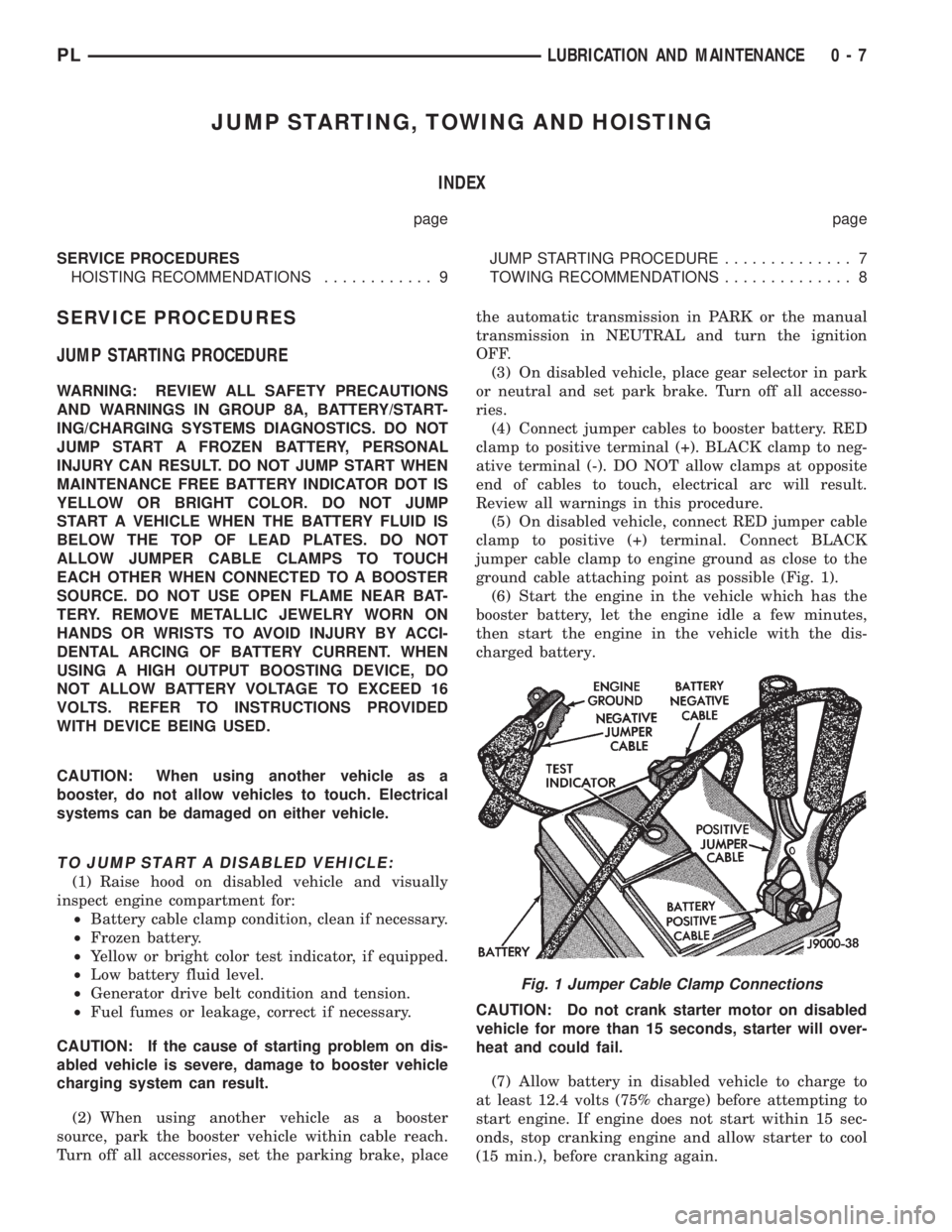
jumper cable clamp to engine ground as close to the
ground cable attaching point as possible (Fig. 1).
(6) Start the engine in the vehicle which has the
booster battery, let the engine idle a few minutes,
then start the engine in the vehicle with the dis-
charged battery.
CAUTION: Do not crank starter motor on disabled
vehicle for more than 15 seconds, starter will over-
heat and could fail.
(7) Allow battery in disabled vehicle to charge to
at least 12.4 volts (75% charge) before attempting to
start engine. If engine does not start within 15 sec-
onds, stop cranking engine and allow starter to cool
(15 min.), before cranking again.
Fig. 1 Jumper Cable Clamp Connections
PLLUBRICATION AND MAINTENANCE 0 - 7
Page 66 of 1200
DIFFERENTIAL AND DRIVELINE
CONTENTS
page page
GENERAL INFORMATION
FRONT DRIVESHAFTS.................... 1
DIAGNOSIS AND TESTING
DRIVESHAFT DIAGNOSIS.................. 2
REMOVAL AND INSTALLATION
FRONT DRIVESHAFTS.................... 2
DISASSEMBLY AND ASSEMBLY
DRIVESHAFT RECONDITION............... 7INNER TRIPOD JOINT SEAL BOOT.......... 9
OUTER C/V JOINT SEAL BOOT............ 13
SPECIFICATIONS
TORQUE.............................. 16
SPECIAL TOOLS
DRIVESHAFT........................... 16
GENERAL INFORMATION
FRONT DRIVESHAFTS
Vehicles equipped with either an automatic or
manual transmission use the unequal±length drive-
shaft system.
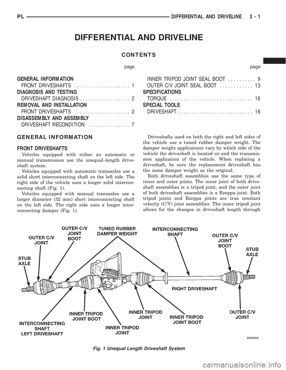
Vehicles equipped with automatic transaxles use a
solid short interconnecting shaft on the left side. The
right side of the vehicle uses a longer solid intercon-
necting shaft (Fig. 1).
Vehicles equipped with manual transaxles use a
larger diameter (32 mm) short interconnecting shaft
on the left side. The right side uses a longer inter-
connecting damper (Fig. 1).Driveshafts used on both the right and left sides of
the vehicle use a tuned rubber damper weight. The
damper weight applications vary by which side of the
vehicle the driveshaft is located on and the transmis-
sion application of the vehicle. When replacing a
driveshaft, be sure the replacement driveshaft has
the same damper weight as the original.
Both driveshaft assemblies use the same type of
inner and outer joints. The inner joint of both drive-
shaft assemblies is a tripod joint, and the outer joint
of both driveshaft assemblies is a Rzeppa joint. Both
tripod joints and Rzeppa joints are true constant
velocity (C/V) joint assemblies. The inner tripod joint
allows for the changes in driveshaft length through
Fig. 1 Unequal Length Driveshaft System
PLDIFFERENTIAL AND DRIVELINE 3 - 1
Page 194 of 1200
COOLING
CONTENTS
page page
GENERAL INFORMATION
ACCESSORY DRIVE BELTS................ 2
AUTOMATIC TRANSMISSION OIL COOLER.... 3
COOLANT RECOVERY SYSTEM (CRS)....... 2
COOLANT.............................. 3
COOLING SYSTEM PRESSURE CAP......... 3
COOLING SYSTEM....................... 1
ENGINE BLOCK HEATER.................. 3
ENGINE THERMOSTAT.................... 3
RADIATOR............................. 3
WATER PUMP.......................... 3
DESCRIPTION AND OPERATION
COOLANT PERFORMANCE................. 4
COOLING SYSTEM PRESSURE CAP......... 5
ENGINE BLOCK HEATER.................. 5
ENGINE THERMOSTAT.................... 4
RADIATOR HOSES AND CLAMPS........... 5
WATER PUMP.......................... 6
DIAGNOSIS AND TESTING
ACCESSORY DRIVEBELT DIAGNOSIS....... 13
COOLING SYSTEM DIAGNOSIS............. 7
COOLING SYSTEM FLOW CHECK.......... 14
DEAERATION.......................... 15
ELECTRIC FAN MOTOR TEST.............. 14
ENGINE THERMOSTAT TESTING........... 13
LOW COOLANT LEVEL AERATION.......... 15
PRESSURE CAP TO FILLER NECK SEAL
PRESSURE RELIEF CHECK.............. 15
PRESSURE TESTING COOLING SYSTEM
PRESSURE CAP...................... 15
RADIATOR FAN CONTROL................ 14
TEMPERATURE GAUGE INDICATION........ 16
TESTING COOLING SYSTEM FOR LEAKS.... 14WATER PUMP DIAGNOSIS............... 14
SERVICE PROCEDURES
COOLANT LEVEL CHECKÐROUTINE........ 16
COOLANT LEVELÐSERVICING............ 16
COOLANTÐADDING ADDITIONAL......... 16
COOLING SYSTEMÐDRAINING............ 16
COOLING SYSTEMÐREFILLING........... 17
REMOVAL AND INSTALLATION
ACCESSORY DRIVE BELTS............... 21
ENGINE BLOCK HEATER................. 21
ENGINE THERMOSTAT................... 18
RADIATOR DRAINCOCK.................. 20
RADIATOR FANS AND MOTOR............ 20
RADIATOR............................ 19
WATER PUMP INLET TUBE............... 18
WATER PUMP......................... 17
CLEANING AND INSPECTION
ACCESSORY DRIVE BELT INSPECTION...... 22
CHEMICAL CLEANING................... 23
CLEANING COOLING SYSTEM............. 22
COOLING SYSTEM CAP.................. 22
RADIATOR FLUSHING................... 23
REVERSE FLUSHING.................... 23
WATER PUMP......................... 21
ADJUSTMENTS
BELT TENSION GAUGE METHOD........... 24
PROPER BELT TENSION................. 23
SPECIFICATIONS
COOLING SYSTEM CAPACITY............. 24
TORQUE.............................. 24
SPECIAL TOOLS
COOLING............................. 24
GENERAL INFORMATION
COOLING SYSTEM
The cooling system consists of an engine cooling
module, thermostat, coolant, and a water pump to
circulate the coolant. The engine cooling module may
consist of a radiator, electric fan motor, fan, shroud,
coolant reserve system, transmission oil cooler, hoses,
clamps, air condition condenser and transmission oil lines.
²When the Engine is cold: The thermostat is
closed; the cooling system has no flow through the
radiator. The coolant flows through the engine,
heater system and bypass.
²When the Engine is warm: Thermostat is open;
the cooling system has flow through radiator, engine,
heater system and bypass.
Coolant flow circuit for the 2.0L engine is shown in
(Fig. 1).
PLCOOLING 7 - 1
Page 196 of 1200
ENGINE THERMOSTAT
The engine thermostat is located on the front of
the engine (radiator side) in the thermostat housing/
engine outlet connector. The thermostat has an air
bleed (vent) located in the flange and a O-ring for
sealing incorporate on it. There is a relief in the ther-
mostat housing/outlet connector for the O-ring.
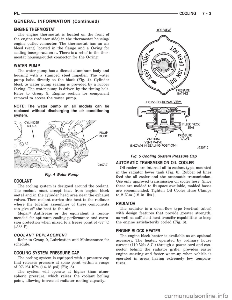
WATER PUMP
The water pump has a diecast aluminum body and
housing with a stamped steel impeller. The water
pump bolts directly to the block (Fig. 4). Cylinder
block to water pump sealing is provided by a rubber
O-ring. The water pump is driven by the timing belt.
Refer to Group 9, Engine section for component
removal to access the water pump.
NOTE: The water pump on all models can be
replaced without discharging the air conditioning
system.
COOLANT
The cooling system is designed around the coolant.
The coolant must accept heat from engine block
metal and in the cylinder head area near the exhaust
valves. Then coolant carries this heat to the radiator
where the tube/fin assemblies of these components
can give off the heat to the air.
MopartAntifreeze or the equivalent is recom-
mended for optimum cooling performance and corro-
sion protection when mixed to a freeze point of -37É C
(-35É F).
COOLANT REPLACEMENT
Refer to Group 0, Lubrication and Maintenance for
schedule.
COOLING SYSTEM PRESSURE CAP
The cooling system is equipped with a pressure cap
that releases pressure at some point within a range
of 97-124 kPa (14-18 psi) (Fig. 5).
The system will operate at higher than atmo-
spheric pressure, which raises the coolant boiling
point, allowing increased radiator cooling capacity.
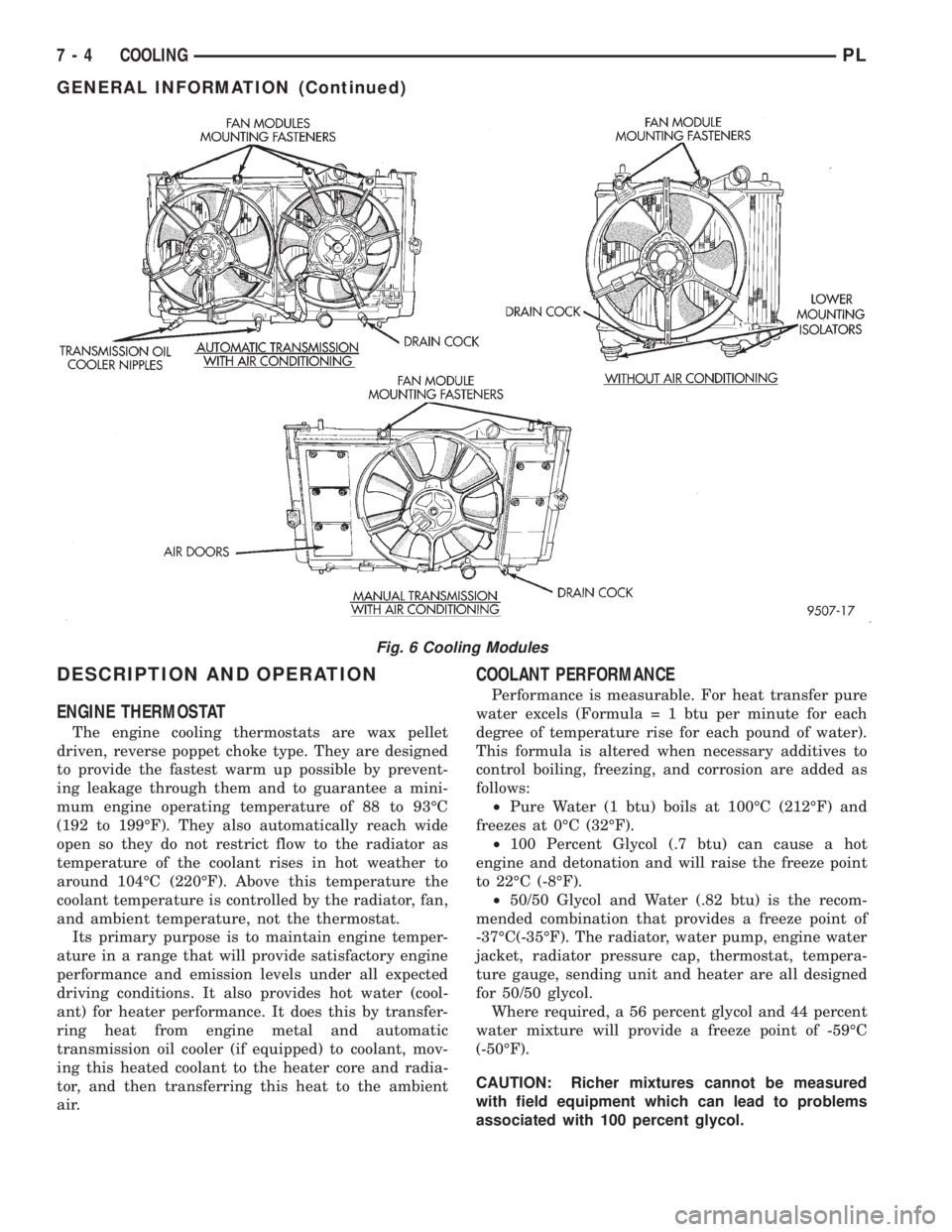
AUTOMATIC TRANSMISSION OIL COOLER
Oil coolers are internal oil to coolant type, mounted
in the radiator lower tank (Fig. 6). Rubber oil lines
feed the oil cooler and the automatic transmission.
Use only approved transmission oil cooler hose. Since
these are molded to fit space available, molded hoses
are recommended. Tighten Oil Cooler Hose Clamps
to 2 N´m (18 in. lbs.).
RADIATOR
The radiator is a down-flow type (vertical tubes)
with design features that provide greater strength,
as well as sufficient heat transfer capabilities to keep
the engine satisfactorily cooled (Fig. 6).
ENGINE BLOCK HEATER
The engine block heater is available as an optional
accessory. The heater, operated by ordinary house
current (110 Volt A.C.) through a power cord and con-
nector behind the radiator grille, provides easier
engine starting and faster warm-up when vehicle is
operated in areas having extremely low tempera-
tures.
Fig. 4 Water Pump
Fig. 5 Cooling System Pressure Cap
PLCOOLING 7 - 3
GENERAL INFORMATION (Continued)
Page 197 of 1200
DESCRIPTION AND OPERATION
ENGINE THERMOSTAT
The engine cooling thermostats are wax pellet
driven, reverse poppet choke type. They are designed
to provide the fastest warm up possible by prevent-
ing leakage through them and to guarantee a mini-
mum engine operating temperature of 88 to 93ÉC
(192 to 199ÉF). They also automatically reach wide
open so they do not restrict flow to the radiator as
temperature of the coolant rises in hot weather to
around 104ÉC (220ÉF). Above this temperature the
coolant temperature is controlled by the radiator, fan,
and ambient temperature, not the thermostat.
Its primary purpose is to maintain engine temper-
ature in a range that will provide satisfactory engine
performance and emission levels under all expected
driving conditions. It also provides hot water (cool-
ant) for heater performance. It does this by transfer-
ring heat from engine metal and automatic
transmission oil cooler (if equipped) to coolant, mov-
ing this heated coolant to the heater core and radia-
tor, and then transferring this heat to the ambient
air.
COOLANT PERFORMANCE
Performance is measurable. For heat transfer pure
water excels (Formula = 1 btu per minute for each
degree of temperature rise for each pound of water).
This formula is altered when necessary additives to
control boiling, freezing, and corrosion are added as
follows:
²Pure Water (1 btu) boils at 100ÉC (212ÉF) and
freezes at 0ÉC (32ÉF).
²100 Percent Glycol (.7 btu) can cause a hot
engine and detonation and will raise the freeze point
to 22ÉC (-8ÉF).
²50/50 Glycol and Water (.82 btu) is the recom-
mended combination that provides a freeze point of
-37ÉC(-35ÉF). The radiator, water pump, engine water
jacket, radiator pressure cap, thermostat, tempera-
ture gauge, sending unit and heater are all designed
for 50/50 glycol.
Where required, a 56 percent glycol and 44 percent
water mixture will provide a freeze point of -59ÉC
(-50ÉF).
CAUTION: Richer mixtures cannot be measured
with field equipment which can lead to problems
associated with 100 percent glycol.
Fig. 6 Cooling Modules
7 - 4 COOLINGPL
GENERAL INFORMATION (Continued)