1999 DODGE NEON low oil pressure
[x] Cancel search: low oil pressurePage 4 of 1200
MAINTENANCE SCHEDULES
INDEX
page page
GENERAL INFORMATION
INTRODUCTION......................... 3
SCHEDULE ± A.......................... 3SCHEDULE ± B.......................... 4
UNSCHEDULED INSPECTION............... 3
GENERAL INFORMATION
INTRODUCTION
Service and maintenance procedures for compo-
nents and systems listed in Schedule ± A or B can be
found by using the Group Tab Locator index at the
front of this manual. If it is not clear which group
contains the information needed, refer to the index at
the back of this manual.
There are two maintenance schedules that show
proper service based on the conditions that the vehi-
cle is subjected to. Use the schedule that best
describes these conditions.
Schedule ±A, lists maintenance recommended for
vehicles used for general transportation.
Schedule ±B, lists maintenance recommended for
vehicles used under the following conditions:
²Frequent short trip driving less than 5 miles (8
km)
²Frequent driving in dusty conditions
²Frequent trailer towing
²Extensive idling
²More than 50% of your driving is at sustained
high speeds during hot weather, above 90ÉF (32ÉC)
Where time and mileage are listed, follow the
interval that occurs first.
EMISSION CONTROL SYSTEM MAINTENANCE
The scheduled emission maintenance listed inbold
typeon the Maintenance Schedules, must be done at
the mileage specified to assure the continued proper
functioning of the emission control system. These,
and all other maintenance services included in this
manual, should be done to provide the best vehicle
performance and reliability. More frequent mainte-
nance may be needed for vehicles in severe operating
conditions such as dusty areas and very short trip
driving.
UNSCHEDULED INSPECTION
At Each Stop For Fuel
²Check engine oil level, add as required.
²Check windshield washer solvent and add if
required.
Once A Month
²Check tire pressure and look for unusual wear
or damage.
²Inspect battery, clean, and tighten terminals as
required.
²Check fluid levels of coolant reservoir, power
steering and automatic transmission and add as
required.
²Check all lights and all other electrical items for
correct operation.
At Each Oil Change
²Inspect exhaust system.
²Inspect brake hoses.
²Inspect the CV joints and front suspension com-
ponents.
²Rotate the tires at each oil change interval
shown on Schedule ± A (7,500 miles) or every other
interval shown on schedule ± B (6,000 miles).
²Check coolant level, hoses and clamps.
²Check the manual transaxle fluid level.
²If the mileage is less than 7,500 miles (12 000
km) yearly, replace the engine oil filter at each oil
change.
SCHEDULE ± A
7,500 Miles (12 000 km) or at 6 months
²Change engine oil.
15,000 Miles (24 000 km) or at 12 months
²Change engine oil.
²Replace engine oil filter.
²Adjust drive belt tension.
22,500 Miles (36 000 km) or at 18 months
²Change engine oil.
²Inspect the front brake pads and rear brake lin-
ings.
30,000 Miles (48 000 km) or at 24 months
²Change engine oil.
²Replace engine oil filter.
²Lubricate front suspension ball joints.
²Adjust drive belt tension.
PLLUBRICATION AND MAINTENANCE 0 - 3
Page 100 of 1200
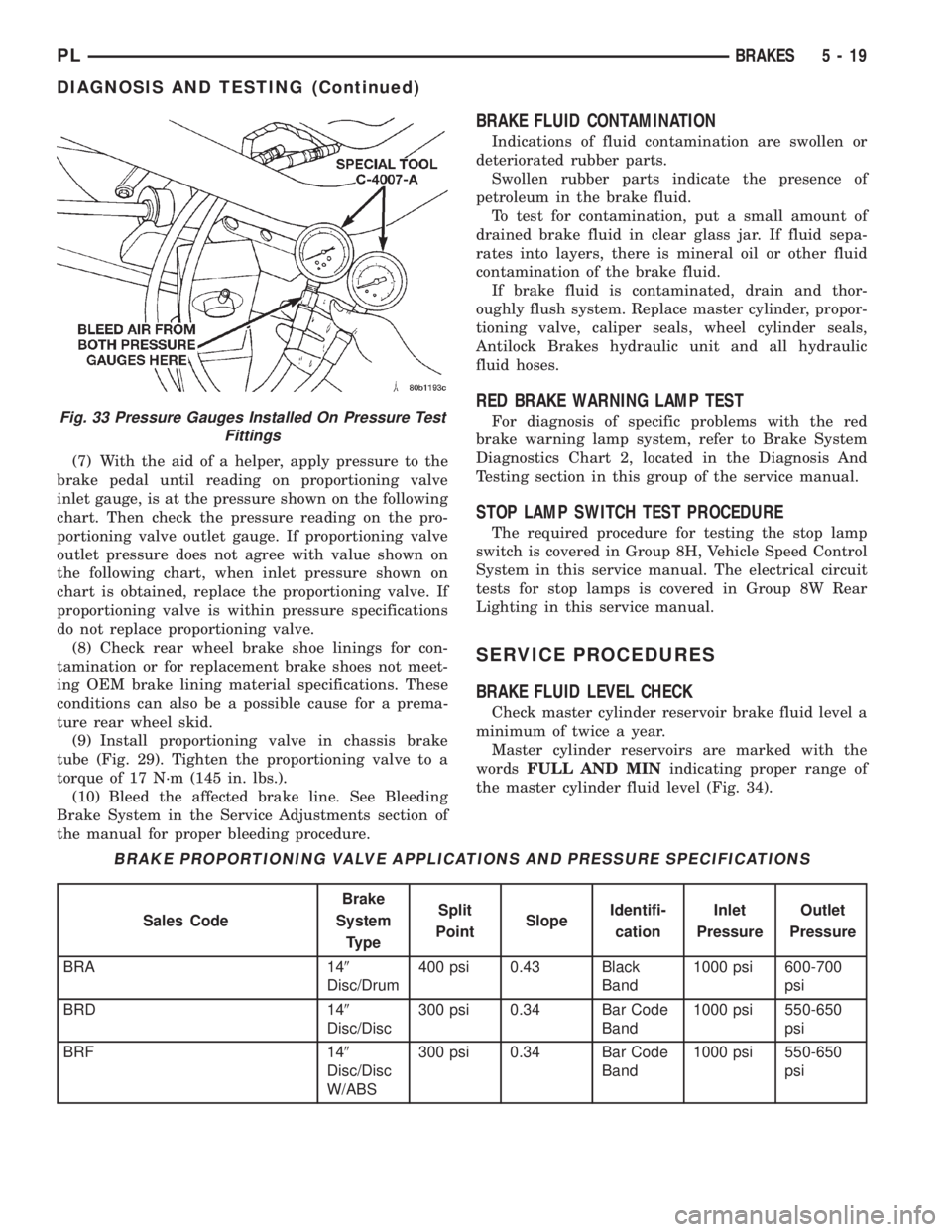
(7) With the aid of a helper, apply pressure to the
brake pedal until reading on proportioning valve
inlet gauge, is at the pressure shown on the following
chart. Then check the pressure reading on the pro-
portioning valve outlet gauge. If proportioning valve
outlet pressure does not agree with value shown on
the following chart, when inlet pressure shown on
chart is obtained, replace the proportioning valve. If
proportioning valve is within pressure specifications
do not replace proportioning valve.
(8) Check rear wheel brake shoe linings for con-
tamination or for replacement brake shoes not meet-
ing OEM brake lining material specifications. These
conditions can also be a possible cause for a prema-
ture rear wheel skid.
(9) Install proportioning valve in chassis brake
tube (Fig. 29). Tighten the proportioning valve to a
torque of 17 N´m (145 in. lbs.).
(10) Bleed the affected brake line. See Bleeding
Brake System in the Service Adjustments section of
the manual for proper bleeding procedure.
BRAKE FLUID CONTAMINATION
Indications of fluid contamination are swollen or
deteriorated rubber parts.
Swollen rubber parts indicate the presence of
petroleum in the brake fluid.
To test for contamination, put a small amount of
drained brake fluid in clear glass jar. If fluid sepa-
rates into layers, there is mineral oil or other fluid
contamination of the brake fluid.
If brake fluid is contaminated, drain and thor-
oughly flush system. Replace master cylinder, propor-
tioning valve, caliper seals, wheel cylinder seals,
Antilock Brakes hydraulic unit and all hydraulic
fluid hoses.
RED BRAKE WARNING LAMP TEST
For diagnosis of specific problems with the red
brake warning lamp system, refer to Brake System
Diagnostics Chart 2, located in the Diagnosis And
Testing section in this group of the service manual.
STOP LAMP SWITCH TEST PROCEDURE
The required procedure for testing the stop lamp
switch is covered in Group 8H, Vehicle Speed Control
System in this service manual. The electrical circuit
tests for stop lamps is covered in Group 8W Rear
Lighting in this service manual.
SERVICE PROCEDURES
BRAKE FLUID LEVEL CHECK
Check master cylinder reservoir brake fluid level a
minimum of twice a year.
Master cylinder reservoirs are marked with the
wordsFULL AND MINindicating proper range of
the master cylinder fluid level (Fig. 34).
Fig. 33 Pressure Gauges Installed On Pressure Test
Fittings
BRAKE PROPORTIONING VALVE APPLICATIONS AND PRESSURE SPECIFICATIONS
Sales CodeBrake
System
TypeSplit
PointSlopeIdentifi-
cationInlet
PressureOutlet
Pressure
BRA 149
Disc/Drum400 psi 0.43 Black
Band1000 psi 600-700
psi
BRD 149
Disc/Disc300 psi 0.34 Bar Code
Band1000 psi 550-650
psi
BRF 149
Disc/Disc
W/ABS300 psi 0.34 Bar Code
Band1000 psi 550-650
psi
PLBRAKES 5 - 19
DIAGNOSIS AND TESTING (Continued)
Page 148 of 1200
(3) Remove the rubber plug from the adjusting
hole in the brake shoe backing plate on both sides of
the vehicle.
(4)Driver (left) side park brake shoe adjust-
ment procedure.Insert a medium size screwdriver
through adjustment hole in backing plate. Position
the srewdriver against the starwheel on the park
brake shoe adjuster mechanism. Using the screw-
driver rotate the starwheeldownwarduntil a slight
drag is felt when turning the rear tire and wheel.
Then, using the screwdriver rotate the starwheel
upwardjust until the rear tire and wheel can be
rotated with no park brake shoe drag. From the
point where there is no more park brake drag rotate
the starwheelupwarda maximum of two additional
clicks. The park brake shoe to drum clearance is
know properly adjusted.
(5)Passenger (right) side park brake shoe
adjustment procedure.Insert a medium size
screwdriver through adjustment hole in backing
plate. Position the srewdriver against the starwheel
on the park brake shoe adjuster mechanism. Using
the screwdriver rotate the starwheelupwarduntil a
slight drag is felt when turning the rear tire and
wheel. Then, using the screwdriver rotate the star-
wheeldownwardjust until the rear tire and wheel
can be rotated with no park brake shoe drag. From
the point where there is no more park brake drag
rotate the starwheeldownwarda maximum of two
additional clicks. The park brake shoe to drum clear-
ance is know properly adjusted.
(6) Install the rubber plug in the adjusting hole on
the brake shoe backing plate on both sides of the
vehicle.
(7) Lower vehicle far enough to allow access the
park brake lever. The rear tires must not be on the
ground.
(8) Fully apply and release the park brakes two
times after adjusting the park brake shoes. Then
rotate both rear wheels to ensure that the park
brake shoes do not drag on the brake drum following
the application and release of the park brakes.
SPECIFICATIONS
BRAKE FLUID
The brake fluid used in this vehicle must conform
to DOT 3 specifications and SAE J1703 standards.
No other type of brake fluid is recommended or
approved for usage in the vehicle brake system. Use
only Mopar brake fluid or an equivalent from a
tightly sealed container.
CAUTION: Never use reclaimed brake fluid or fluid
from an container which has been left open. Anopen container will absorb moisture from the air
and contaminate the fluid.
CAUTION: Never use any type of a petroleum-
based fluid in the brake hydraulic system. Use of
such type fluids will result in seal damage of the
vehicle brake hydraulic system causing a failure of
the vehicle brake system. Petroleum based fluids
would be items such as engine oil, transmission
fluid, power steering fluid ect.
BRAKE ACTUATION SYSTEM
ACTUATION:
Vacuum Operated Power Brakes.........Standard
Hydraulic System...........Dual-Diagonally Split
MASTER CYLINDER ASSEMBLY:
Type ...........................Dual Tandem
Body Material...............Anodized Aluminum
Reservoir Material................Polypropelene
MASTER CYLINDER BORE / STROKE
AND SPLIT:
NonABS ....21mmx32.6 mm (.875 in. x 1.28 in.)
ABS........21mmx32.7 mm (.874 in. x 1.29 in.)
Displacement Split.....................50/50
MASTER CYLINDER FLUID OUTLET PORTS:
ABS ..........Primary 3/8±24 Secondary 7/16±24
Non ABS . . .Primary Inboard And Outboard 7/16±24
Non ABS . . .Secondary Inboard And Outboard 3/8±23
Outlet Fitting Type.......SAE 45 É Inverted Flare
ABS HYDRAULIC CONTROL UNIT:
Hydraulic Tube Fitting Type.SAE 45 É Inverted Flare
BOOSTER:
Make/Type.........Bendix Vacuum W/&W/O ABS
Mounting Studs.....................M8x1.25
Type ..........................230 mm Single
Boost At 20 inches Of Manifold Vacuum. . . .4690 All
PROPORTIONING VALVE:
Material...........................Aluminum
Function........Hydraulic Pressure Proportioning
BRAKE PEDAL
Pedal Ratio.............................3.28
BRAKE FASTENER TORQUE SPECIFICATIONS
DESCRIPTION TORQUE
BRAKE TUBES:
Tube Nuts To Fittings And
Components Except HCU. . . . 17 N´m (145 in. lbs.)
From Master Cylinder To
HCU At HCU Ports........21N´m(185 in. lbs.)
BRAKE HOSE:
To Caliper Banjo Bolt..........48N´m(35ft.lbs.)
Intermediate Bracket.........12N´m(105 in. lbs.)
PLBRAKES 5 - 67
ADJUSTMENTS (Continued)
Page 179 of 1200
REMOVAL
(1) Remove transaxle. See Group 21, Manual Tran-
saxle, for procedure.
(2) Mark clutch cover and flywheel, to maintain
their same relative positions when installing clutch
assembly.
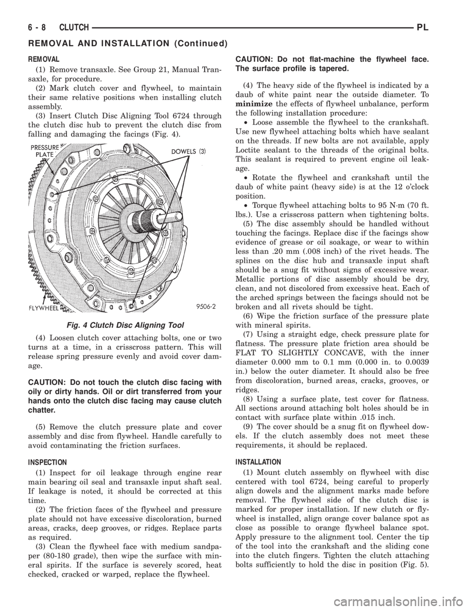
(3) Insert Clutch Disc Aligning Tool 6724 through
the clutch disc hub to prevent the clutch disc from
falling and damaging the facings (Fig. 4).
(4) Loosen clutch cover attaching bolts, one or two
turns at a time, in a crisscross pattern. This will
release spring pressure evenly and avoid cover dam-
age.
CAUTION: Do not touch the clutch disc facing with
oily or dirty hands. Oil or dirt transferred from your
hands onto the clutch disc facing may cause clutch
chatter.
(5) Remove the clutch pressure plate and cover
assembly and disc from flywheel. Handle carefully to
avoid contaminating the friction surfaces.
INSPECTION
(1) Inspect for oil leakage through engine rear
main bearing oil seal and transaxle input shaft seal.
If leakage is noted, it should be corrected at this
time.
(2) The friction faces of the flywheel and pressure
plate should not have excessive discoloration, burned
areas, cracks, deep grooves, or ridges. Replace parts
as required.
(3) Clean the flywheel face with medium sandpa-
per (80-180 grade), then wipe the surface with min-
eral spirits. If the surface is severely scored, heat
checked, cracked or warped, replace the flywheel.CAUTION: Do not flat-machine the flywheel face.
The surface profile is tapered.
(4) The heavy side of the flywheel is indicated by a
daub of white paint near the outside diameter. To
minimizethe effects of flywheel unbalance, perform
the following installation procedure:
²Loose assemble the flywheel to the crankshaft.
Use new flywheel attaching bolts which have sealant
on the threads. If new bolts are not available, apply
Loctite sealant to the threads of the original bolts.
This sealant is required to prevent engine oil leak-
age.
²Rotate the flywheel and crankshaft until the
daub of white paint (heavy side) is at the 12 o'clock
position.
²Torque flywheel attaching bolts to 95 N´m (70 ft.
lbs.). Use a crisscross pattern when tightening bolts.
(5) The disc assembly should be handled without
touching the facings. Replace disc if the facings show
evidence of grease or oil soakage, or wear to within
less than .20 mm (.008 inch) of the rivet heads. The
splines on the disc hub and transaxle input shaft
should be a snug fit without signs of excessive wear.
Metallic portions of disc assembly should be dry,
clean, and not discolored from excessive heat. Each of
the arched springs between the facings should not be
broken and all rivets should be tight.
(6) Wipe the friction surface of the pressure plate
with mineral spirits.
(7) Using a straight edge, check pressure plate for
flatness. The pressure plate friction area should be
FLAT TO SLIGHTLY CONCAVE, with the inner
diameter 0.000 mm to 0.1 mm (0.000 in. to 0.0039
in.) below the outer diameter. It should also be free
from discoloration, burned areas, cracks, grooves, or
ridges.
(8) Using a surface plate, test cover for flatness.
All sections around attaching bolt holes should be in
contact with surface plate within .015 inch.
(9) The cover should be a snug fit on flywheel dow-
els. If the clutch assembly does not meet these
requirements, it should be replaced.
INSTALLATION
(1) Mount clutch assembly on flywheel with disc
centered with tool 6724, being careful to properly
align dowels and the alignment marks made before
removal. The flywheel side of the clutch disc is
marked for proper installation. If new clutch or fly-
wheel is installed, align orange cover balance spot as
close as possible to orange flywheel balance spot.
Apply pressure to the alignment tool. Center the tip
of the tool into the crankshaft and the sliding cone
into the clutch fingers. Tighten the clutch attaching
bolts sufficiently to hold the disc in position (Fig. 5).
Fig. 4 Clutch Disc Aligning Tool
6 - 8 CLUTCHPL
REMOVAL AND INSTALLATION (Continued)
Page 180 of 1200
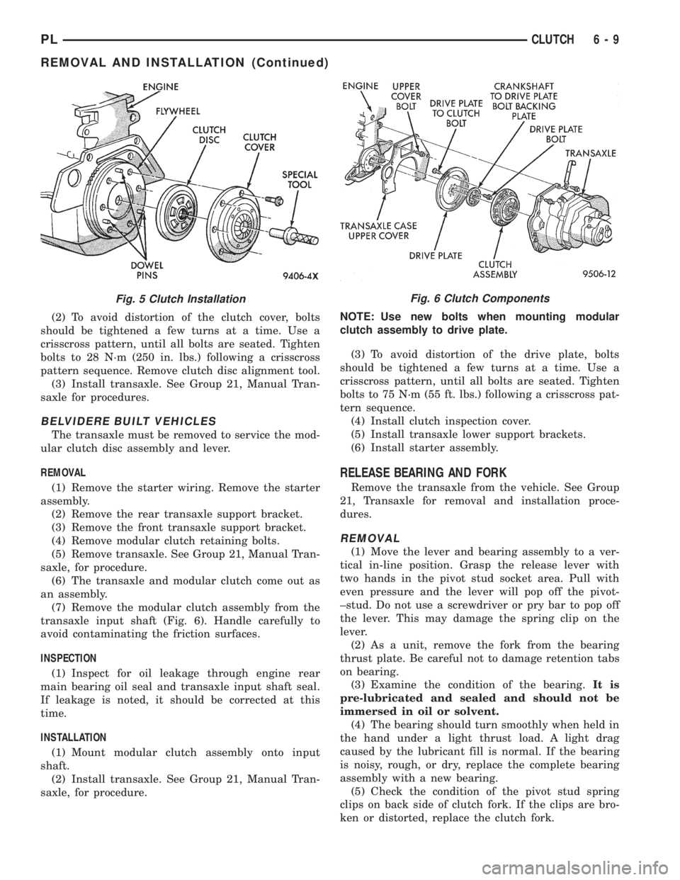
(2) To avoid distortion of the clutch cover, bolts
should be tightened a few turns at a time. Use a
crisscross pattern, until all bolts are seated. Tighten
bolts to 28 N´m (250 in. lbs.) following a crisscross
pattern sequence. Remove clutch disc alignment tool.
(3) Install transaxle. See Group 21, Manual Tran-
saxle for procedures.
BELVIDERE BUILT VEHICLES
The transaxle must be removed to service the mod-
ular clutch disc assembly and lever.
REMOVAL
(1) Remove the starter wiring. Remove the starter
assembly.
(2) Remove the rear transaxle support bracket.
(3) Remove the front transaxle support bracket.
(4) Remove modular clutch retaining bolts.
(5) Remove transaxle. See Group 21, Manual Tran-
saxle, for procedure.
(6) The transaxle and modular clutch come out as
an assembly.
(7) Remove the modular clutch assembly from the
transaxle input shaft (Fig. 6). Handle carefully to
avoid contaminating the friction surfaces.
INSPECTION
(1) Inspect for oil leakage through engine rear
main bearing oil seal and transaxle input shaft seal.
If leakage is noted, it should be corrected at this
time.
INSTALLATION
(1) Mount modular clutch assembly onto input
shaft.
(2) Install transaxle. See Group 21, Manual Tran-
saxle, for procedure.NOTE: Use new bolts when mounting modular
clutch assembly to drive plate.
(3) To avoid distortion of the drive plate, bolts
should be tightened a few turns at a time. Use a
crisscross pattern, until all bolts are seated. Tighten
bolts to 75 N´m (55 ft. lbs.) following a crisscross pat-
tern sequence.
(4) Install clutch inspection cover.
(5) Install transaxle lower support brackets.
(6) Install starter assembly.
RELEASE BEARING AND FORK
Remove the transaxle from the vehicle. See Group
21, Transaxle for removal and installation proce-
dures.
REMOVAL
(1) Move the lever and bearing assembly to a ver-
tical in-line position. Grasp the release lever with
two hands in the pivot stud socket area. Pull with
even pressure and the lever will pop off the pivot-
±stud. Do not use a screwdriver or pry bar to pop off
the lever. This may damage the spring clip on the
lever.
(2) As a unit, remove the fork from the bearing
thrust plate. Be careful not to damage retention tabs
on bearing.
(3) Examine the condition of the bearing.It is
pre-lubricated and sealed and should not be
immersed in oil or solvent.
(4) The bearing should turn smoothly when held in
the hand under a light thrust load. A light drag
caused by the lubricant fill is normal. If the bearing
is noisy, rough, or dry, replace the complete bearing
assembly with a new bearing.
(5) Check the condition of the pivot stud spring
clips on back side of clutch fork. If the clips are bro-
ken or distorted, replace the clutch fork.
Fig. 6 Clutch ComponentsFig. 5 Clutch Installation
PLCLUTCH 6 - 9
REMOVAL AND INSTALLATION (Continued)
Page 181 of 1200
INSTALLATION
(1) The pivot ball pocket in the fork is Teflon
coated and should be installed WITHOUT any lubri-
cant such as grease. Using grease will break down
the Teflon coating. Be sure the ball stud and fork
pocket are clean of contamination and dirt.
(2) Assemble the fork to the bearing. The small
pegs on the bearing must go over the fork arms.
(3) Slide the bearing and fork assembly onto the
input shaft bearing retainer, as a unit.
(4) Snap the clutch fork onto the pivot ball.
(5) Reinstall transaxle assembly. Refer to Group
21, Transaxle for further information.
CLEANING AND INSPECTION
CLUTCH CONTAMINATION
Fluid contamination is a frequent cause of clutch
malfunctions. Oil, grease, water, or other fluids on
the clutch contact surfaces will cause faulty opera-
tion.
During inspection, note if any components are con-
taminated. Look for evidence of oil, grease, or water/
road splash on clutch components.
OIL CONTAMINATION
Oil contamination indicates a leak at the rear main
seal and/or transaxle input shaft. Oil leaks produce a
residue of oil on the transaxle housing interior, clutch
cover and flywheel. Heat buildup caused by slippage
can bake the oil residue onto the components. This
glaze-like residue ranges in color from amber to
black.
GREASE CONTAMINATION
Grease contamination is usually a product of over-
lubrication. During clutch service, apply only a small
amount of grease to the input shaft splines. Excess
grease may be thrown off during operation, contami-
nating the disc.
ROAD SPLASH/WATER CONTAMINATION
Road splash contamination is usually caused by
driving the vehicle through deep water puddles.
Water can be forced into the clutch housing, causing
clutch components to become contaminated. Facing of
disc will absorb moisture and bond to the flywheel
and/or, pressure plate, if vehicle is allowed to stand
for some time before use. If this condition occurs,
replacement of clutch assembly may be required.
Drive the vehicle until normal clutch operating tem-
perature has been obtained. This will dry off disc
assembly, pressure plate, and flywheel.
CLEANING PRECAUTIONS
Condensation from steam vapors tend to accumu-
late on the internal clutch mechanism when the vehi-
cle is steam cleaned. Facing of disc will absorb
moisture and will bond to flywheel and/or pressure
plate, if vehicle is allowed to stand for some time
before use. If this condition occurs, it may require
replacement of clutch assembly. After cleaning, drive
the vehicle to its normal clutch operating tempera-
ture. This will dry off disc assembly, pressure plate,
and flywheel.
ADJUSTMENTS
CLUTCH CABLE
The manual transaxle clutch release system has a
unique self-adjusting mechanism to compensate for
clutch disc wear. This adjuster mechanism is located
within the clutch cable assembly. The preload spring
maintains tension on the cable. This tension keeps
the clutch release bearing continuously loaded
against the fingers of the clutch cover assembly.
ADJUSTER MECHANISM FUNCTION CHECK
(1) With slight pressure, pull the clutch release
lever end of the cable to draw the cable taut. Push
the clutch cable housing toward the dash panel. With
less than 25 lbs. of effort the cable housing should
move 30-50mm. This indicates proper adjuster mech-
anism function. If the cable does not adjust, deter-
mine if the mechanism is properly seated on the
bracket.
(2) If the adjust mechanism functions properly,
guide the cable through the slot in the transaxle
housing. Connect cable to release lever, seating the
cupped washer securely on lever tangs.
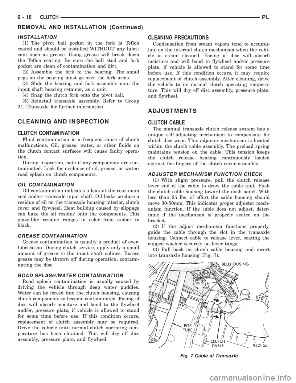
(3) Pull back on clutch cable housing and insert
into transaxle housing (Fig. 7).
Fig. 7 Cable at Transaxle
6 - 10 CLUTCHPL
REMOVAL AND INSTALLATION (Continued)
Page 194 of 1200
COOLING
CONTENTS
page page
GENERAL INFORMATION
ACCESSORY DRIVE BELTS................ 2
AUTOMATIC TRANSMISSION OIL COOLER.... 3
COOLANT RECOVERY SYSTEM (CRS)....... 2
COOLANT.............................. 3
COOLING SYSTEM PRESSURE CAP......... 3
COOLING SYSTEM....................... 1
ENGINE BLOCK HEATER.................. 3
ENGINE THERMOSTAT.................... 3
RADIATOR............................. 3
WATER PUMP.......................... 3
DESCRIPTION AND OPERATION
COOLANT PERFORMANCE................. 4
COOLING SYSTEM PRESSURE CAP......... 5
ENGINE BLOCK HEATER.................. 5
ENGINE THERMOSTAT.................... 4
RADIATOR HOSES AND CLAMPS........... 5
WATER PUMP.......................... 6
DIAGNOSIS AND TESTING
ACCESSORY DRIVEBELT DIAGNOSIS....... 13
COOLING SYSTEM DIAGNOSIS............. 7
COOLING SYSTEM FLOW CHECK.......... 14
DEAERATION.......................... 15
ELECTRIC FAN MOTOR TEST.............. 14
ENGINE THERMOSTAT TESTING........... 13
LOW COOLANT LEVEL AERATION.......... 15
PRESSURE CAP TO FILLER NECK SEAL
PRESSURE RELIEF CHECK.............. 15
PRESSURE TESTING COOLING SYSTEM
PRESSURE CAP...................... 15
RADIATOR FAN CONTROL................ 14
TEMPERATURE GAUGE INDICATION........ 16
TESTING COOLING SYSTEM FOR LEAKS.... 14WATER PUMP DIAGNOSIS............... 14
SERVICE PROCEDURES
COOLANT LEVEL CHECKÐROUTINE........ 16
COOLANT LEVELÐSERVICING............ 16
COOLANTÐADDING ADDITIONAL......... 16
COOLING SYSTEMÐDRAINING............ 16
COOLING SYSTEMÐREFILLING........... 17
REMOVAL AND INSTALLATION
ACCESSORY DRIVE BELTS............... 21
ENGINE BLOCK HEATER................. 21
ENGINE THERMOSTAT................... 18
RADIATOR DRAINCOCK.................. 20
RADIATOR FANS AND MOTOR............ 20
RADIATOR............................ 19
WATER PUMP INLET TUBE............... 18
WATER PUMP......................... 17
CLEANING AND INSPECTION
ACCESSORY DRIVE BELT INSPECTION...... 22
CHEMICAL CLEANING................... 23
CLEANING COOLING SYSTEM............. 22
COOLING SYSTEM CAP.................. 22
RADIATOR FLUSHING................... 23
REVERSE FLUSHING.................... 23
WATER PUMP......................... 21
ADJUSTMENTS
BELT TENSION GAUGE METHOD........... 24
PROPER BELT TENSION................. 23
SPECIFICATIONS
COOLING SYSTEM CAPACITY............. 24
TORQUE.............................. 24
SPECIAL TOOLS
COOLING............................. 24
GENERAL INFORMATION
COOLING SYSTEM
The cooling system consists of an engine cooling
module, thermostat, coolant, and a water pump to
circulate the coolant. The engine cooling module may
consist of a radiator, electric fan motor, fan, shroud,
coolant reserve system, transmission oil cooler, hoses,
clamps, air condition condenser and transmission oil lines.
²When the Engine is cold: The thermostat is
closed; the cooling system has no flow through the
radiator. The coolant flows through the engine,
heater system and bypass.
²When the Engine is warm: Thermostat is open;
the cooling system has flow through radiator, engine,
heater system and bypass.
Coolant flow circuit for the 2.0L engine is shown in
(Fig. 1).
PLCOOLING 7 - 1
Page 196 of 1200
ENGINE THERMOSTAT
The engine thermostat is located on the front of
the engine (radiator side) in the thermostat housing/
engine outlet connector. The thermostat has an air
bleed (vent) located in the flange and a O-ring for
sealing incorporate on it. There is a relief in the ther-
mostat housing/outlet connector for the O-ring.
WATER PUMP
The water pump has a diecast aluminum body and
housing with a stamped steel impeller. The water
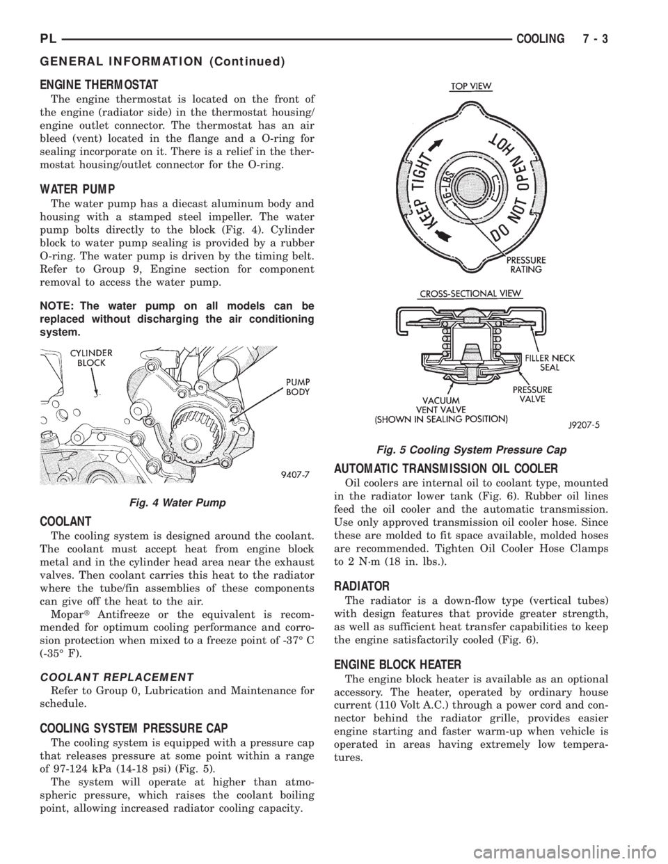
pump bolts directly to the block (Fig. 4). Cylinder
block to water pump sealing is provided by a rubber
O-ring. The water pump is driven by the timing belt.
Refer to Group 9, Engine section for component
removal to access the water pump.
NOTE: The water pump on all models can be
replaced without discharging the air conditioning
system.
COOLANT
The cooling system is designed around the coolant.
The coolant must accept heat from engine block
metal and in the cylinder head area near the exhaust
valves. Then coolant carries this heat to the radiator
where the tube/fin assemblies of these components
can give off the heat to the air.
MopartAntifreeze or the equivalent is recom-
mended for optimum cooling performance and corro-
sion protection when mixed to a freeze point of -37É C
(-35É F).
COOLANT REPLACEMENT
Refer to Group 0, Lubrication and Maintenance for
schedule.
COOLING SYSTEM PRESSURE CAP
The cooling system is equipped with a pressure cap
that releases pressure at some point within a range
of 97-124 kPa (14-18 psi) (Fig. 5).
The system will operate at higher than atmo-
spheric pressure, which raises the coolant boiling
point, allowing increased radiator cooling capacity.
AUTOMATIC TRANSMISSION OIL COOLER
Oil coolers are internal oil to coolant type, mounted
in the radiator lower tank (Fig. 6). Rubber oil lines
feed the oil cooler and the automatic transmission.
Use only approved transmission oil cooler hose. Since
these are molded to fit space available, molded hoses
are recommended. Tighten Oil Cooler Hose Clamps
to 2 N´m (18 in. lbs.).
RADIATOR
The radiator is a down-flow type (vertical tubes)
with design features that provide greater strength,
as well as sufficient heat transfer capabilities to keep
the engine satisfactorily cooled (Fig. 6).
ENGINE BLOCK HEATER
The engine block heater is available as an optional
accessory. The heater, operated by ordinary house
current (110 Volt A.C.) through a power cord and con-
nector behind the radiator grille, provides easier
engine starting and faster warm-up when vehicle is
operated in areas having extremely low tempera-
tures.
Fig. 4 Water Pump
Fig. 5 Cooling System Pressure Cap
PLCOOLING 7 - 3
GENERAL INFORMATION (Continued)