1999 DODGE NEON coolant reservoir
[x] Cancel search: coolant reservoirPage 4 of 1200

MAINTENANCE SCHEDULES
INDEX
page page
GENERAL INFORMATION
INTRODUCTION......................... 3
SCHEDULE ± A.......................... 3SCHEDULE ± B.......................... 4
UNSCHEDULED INSPECTION............... 3
GENERAL INFORMATION
INTRODUCTION
Service and maintenance procedures for compo-
nents and systems listed in Schedule ± A or B can be
found by using the Group Tab Locator index at the
front of this manual. If it is not clear which group
contains the information needed, refer to the index at
the back of this manual.
There are two maintenance schedules that show
proper service based on the conditions that the vehi-
cle is subjected to. Use the schedule that best
describes these conditions.
Schedule ±A, lists maintenance recommended for
vehicles used for general transportation.
Schedule ±B, lists maintenance recommended for
vehicles used under the following conditions:
²Frequent short trip driving less than 5 miles (8
km)
²Frequent driving in dusty conditions
²Frequent trailer towing
²Extensive idling
²More than 50% of your driving is at sustained
high speeds during hot weather, above 90ÉF (32ÉC)
Where time and mileage are listed, follow the
interval that occurs first.
EMISSION CONTROL SYSTEM MAINTENANCE
The scheduled emission maintenance listed inbold
typeon the Maintenance Schedules, must be done at
the mileage specified to assure the continued proper
functioning of the emission control system. These,
and all other maintenance services included in this
manual, should be done to provide the best vehicle
performance and reliability. More frequent mainte-
nance may be needed for vehicles in severe operating
conditions such as dusty areas and very short trip
driving.
UNSCHEDULED INSPECTION
At Each Stop For Fuel
²Check engine oil level, add as required.
²Check windshield washer solvent and add if
required.
Once A Month
²Check tire pressure and look for unusual wear
or damage.
²Inspect battery, clean, and tighten terminals as
required.
²Check fluid levels of coolant reservoir, power
steering and automatic transmission and add as
required.
²Check all lights and all other electrical items for
correct operation.
At Each Oil Change
²Inspect exhaust system.
²Inspect brake hoses.
²Inspect the CV joints and front suspension com-
ponents.
²Rotate the tires at each oil change interval
shown on Schedule ± A (7,500 miles) or every other
interval shown on schedule ± B (6,000 miles).
²Check coolant level, hoses and clamps.
²Check the manual transaxle fluid level.
²If the mileage is less than 7,500 miles (12 000
km) yearly, replace the engine oil filter at each oil
change.
SCHEDULE ± A
7,500 Miles (12 000 km) or at 6 months
²Change engine oil.
15,000 Miles (24 000 km) or at 12 months
²Change engine oil.
²Replace engine oil filter.
²Adjust drive belt tension.
22,500 Miles (36 000 km) or at 18 months
²Change engine oil.
²Inspect the front brake pads and rear brake lin-
ings.
30,000 Miles (48 000 km) or at 24 months
²Change engine oil.
²Replace engine oil filter.
²Lubricate front suspension ball joints.
²Adjust drive belt tension.
PLLUBRICATION AND MAINTENANCE 0 - 3
Page 919 of 1200

(2) Install power steering fluid supply hose on
power steering fluid reservoir fitting. Install hose
clamp on power steering fluid supply hose at power
steering fluid reservoir (Fig. 19).Be sure hose
clamp is installed on return hose past upset
bead on power steering fluid reservoir.
(3) Install power steering fluid supply hose on
power steering pump fitting. Install hose clamp on
power steering fluid supply hose at power steering
pump fitting (Fig. 20).Be sure hose clamp is
installed on power steering fluid supply hose
past upset bead on power steering pump fit-
ting.
(4) Start the engine and let run for a few seconds.
Then turn the engine off.
(5) Add fluid if necessary. Repeat the above proce-
dure until the fluid level remains constant after run-
ning the engine.
(6) Raise front wheels of vehicle off the ground.
(7) Start the engine. Slowly turn the steering
wheel right and left, lightly contacting the wheel
stops. Then turn the engine off.
(8) Add power steering fluid if necessary.
(9) Lower the vehicle and turn the steering wheel
slowly from lock to lock.
(10) Stop the engine. Check the fluid level and
refill as required.
(11) If the fluid is extremely foamy, allow the vehi-
cle to stand a few minutes and repeat the above pro-
cedure.
(12) After hose is installed, check for leaks at all
hose connections.
POWER STEERING PUMP (ALL ENGINES)
WARNING: POWER STEERING OIL, ENGINE COM-
PONENTS AND EXHAUST SYSTEM MAY BE
EXTREMELY HOT IF ENGINE HAS BEEN RUNNING.
DO NOT START ENGINE WITH ANY LOOSE OR DIS-
CONNECTED HOSES, OR ALLOW HOSES TO
TOUCH HOT EXHAUST MANIFOLD OR CATALYST.
The power steering pump removal procedure and
pump and bracket fastener locations are the same for
both engine applications used for this vehicle. The
front power steering pump bracket must be removed
as an assembly with the power steering pump and
removed from the pump after removing the pulley
from the power steering pump.
REMOVE
(1) Remove battery cable from (-) negative post on
battery.
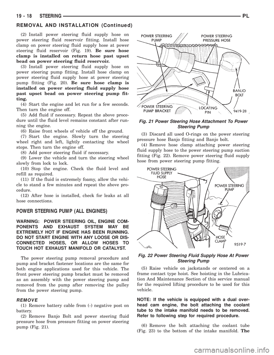
(2) Remove Banjo Bolt and power steering fluid
pressure hose from pressure fitting on power steering
pump (Fig. 21).(3) Discard all used O-rings on the power steering
pressure hose Banjo fitting and Banjo bolt.
(4) Remove hose clamp attaching power steering
fluid supply hose to the power steering pump suction
fitting (Fig. 22). Remove power steering fluid supply
hose from power steering pump fitting.
(5) Raise vehicle on jackstands or centered on a
frame contact type hoist. See hoisting in the Lubrica-
tion And Maintenance Section of this service manual
for the required lifting procedure to be used for this
vehicle.
NOTE: If the vehicle is equipped with a dual over-
head cam engine, the bolt attaching the coolant
tube to the intake manifold needs to be removed.
Refer to following step for required procedure.
(6) Remove the bolt attaching the coolant tube
(Fig. 23) to the bottom of the intake manifold.The
Fig. 21 Power Steering Hose Attachment To Power
Steering Pump
Fig. 22 Power Steering Fluid Supply Hose At Power
Steering Pump
19 - 18 STEERINGPL
REMOVAL AND INSTALLATION (Continued)
Page 922 of 1200

(23) If the fluid is extremely foamy, allow the vehi-
cle to stand a few minutes and repeat the above pro-
cedure.
(24) After power steering pump is installed, check
for leaks at all hose connections and power steering
pump fittings.
POWER STEERING FLUID RESERVOIR
REMOVE
(1) Raise vehicle on jack stands or on a frame con-
tact type hoist. See Hoisting in the Lubrication And
Maintenance Section of this service manual for the
required lifting procedure to be used for this vehicle.
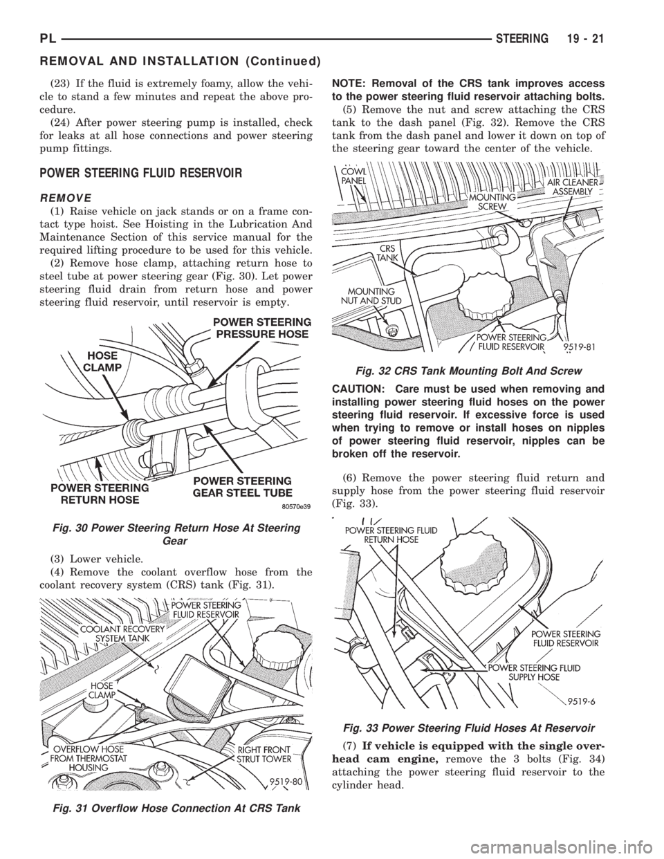
(2) Remove hose clamp, attaching return hose to
steel tube at power steering gear (Fig. 30). Let power
steering fluid drain from return hose and power
steering fluid reservoir, until reservoir is empty.
(3) Lower vehicle.
(4) Remove the coolant overflow hose from the
coolant recovery system (CRS) tank (Fig. 31).NOTE: Removal of the CRS tank improves access
to the power steering fluid reservoir attaching bolts.
(5) Remove the nut and screw attaching the CRS
tank to the dash panel (Fig. 32). Remove the CRS
tank from the dash panel and lower it down on top of
the steering gear toward the center of the vehicle.
CAUTION: Care must be used when removing and
installing power steering fluid hoses on the power
steering fluid reservoir. If excessive force is used
when trying to remove or install hoses on nipples
of power steering fluid reservoir, nipples can be
broken off the reservoir.
(6) Remove the power steering fluid return and
supply hose from the power steering fluid reservoir
(Fig. 33).
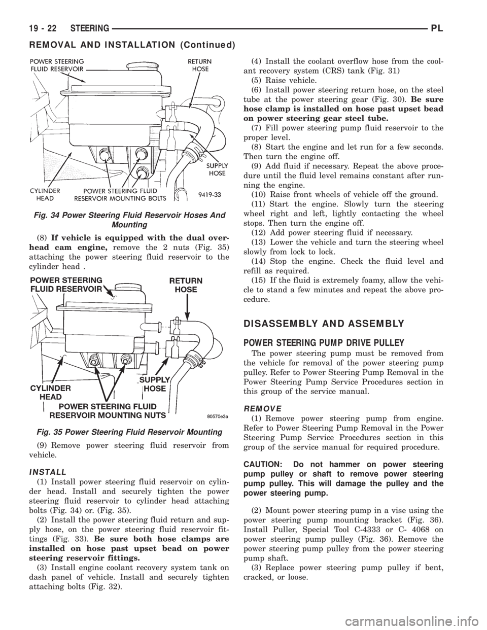
(7)If vehicle is equipped with the single over-
head cam engine,remove the 3 bolts (Fig. 34)
attaching the power steering fluid reservoir to the
cylinder head.
Fig. 30 Power Steering Return Hose At Steering
Gear
Fig. 31 Overflow Hose Connection At CRS Tank
Fig. 32 CRS Tank Mounting Bolt And Screw
Fig. 33 Power Steering Fluid Hoses At Reservoir
PLSTEERING 19 - 21
REMOVAL AND INSTALLATION (Continued)
Page 923 of 1200

(8)If vehicle is equipped with the dual over-
head cam engine,remove the 2 nuts (Fig. 35)
attaching the power steering fluid reservoir to the
cylinder head .
(9) Remove power steering fluid reservoir from
vehicle.
INSTALL
(1) Install power steering fluid reservoir on cylin-
der head. Install and securely tighten the power
steering fluid reservoir to cylinder head attaching
bolts (Fig. 34) or. (Fig. 35).
(2) Install the power steering fluid return and sup-
ply hose, on the power steering fluid reservoir fit-
tings (Fig. 33).Be sure both hose clamps are
installed on hose past upset bead on power
steering reservoir fittings.
(3) Install engine coolant recovery system tank on
dash panel of vehicle. Install and securely tighten
attaching bolts (Fig. 32).(4) Install the coolant overflow hose from the cool-
ant recovery system (CRS) tank (Fig. 31)
(5) Raise vehicle.
(6) Install power steering return hose, on the steel
tube at the power steering gear (Fig. 30).Be sure
hose clamp is installed on hose past upset bead
on power steering gear steel tube.
(7) Fill power steering pump fluid reservoir to the
proper level.
(8) Start the engine and let run for a few seconds.
Then turn the engine off.
(9) Add fluid if necessary. Repeat the above proce-
dure until the fluid level remains constant after run-
ning the engine.
(10) Raise front wheels of vehicle off the ground.
(11) Start the engine. Slowly turn the steering
wheel right and left, lightly contacting the wheel
stops. Then turn the engine off.
(12) Add power steering fluid if necessary.
(13) Lower the vehicle and turn the steering wheel
slowly from lock to lock.
(14) Stop the engine. Check the fluid level and
refill as required.
(15) If the fluid is extremely foamy, allow the vehi-
cle to stand a few minutes and repeat the above pro-
cedure.
DISASSEMBLY AND ASSEMBLY
POWER STEERING PUMP DRIVE PULLEY
The power steering pump must be removed from
the vehicle for removal of the power steering pump
pulley. Refer to Power Steering Pump Removal in the
Power Steering Pump Service Procedures section in
this group of the service manual.
REMOVE
(1) Remove power steering pump from engine.
Refer to Power Steering Pump Removal in the Power
Steering Pump Service Procedures section in this
group of the service manual for required procedure.
CAUTION: Do not hammer on power steering
pump pulley or shaft to remove power steering
pump pulley. This will damage the pulley and the
power steering pump.
(2) Mount power steering pump in a vise using the
power steering pump mounting bracket (Fig. 36).
Install Puller, Special Tool C-4333 or C- 4068 on
power steering pump pulley (Fig. 36). Remove the
power steering pump pulley from the power steering
pump shaft.
(3) Replace power steering pump pulley if bent,
cracked, or loose.
Fig. 34 Power Steering Fluid Reservoir Hoses And
Mounting
Fig. 35 Power Steering Fluid Reservoir Mounting
19 - 22 STEERINGPL
REMOVAL AND INSTALLATION (Continued)