1999 DODGE NEON run flat
[x] Cancel search: run flatPage 16 of 1200
PRE-ALIGNMENT VEHICLE INSPECTION
CAUTION: If the front suspension crossmember
shows any sign of impact damage, the steering col-
umn to steering gear coupling must be inspected.
Refer to Group 19 Steering in this service manual
for the inspection procedure.
Before any attempt is made to change or correct
the wheel alignment factors, the following inspection
and necessary corrections must be made on those
parts which influence the steering of the vehicle.
(1) Be sure the fuel tank is full when the wheel
alignment specifications are checked and or adjusted.
A full tank of fuel weighs approximately 75 pounds,
if the fuel tank is not full this reduction in weight
will affect the curb height of the vehicle and the
alignment specifications.
(2) Alignment specifications of a vehicle can be the
most accurately checked and set when the passenger
compartment and trunk of the vehicle are vacant
with the exception of the spare tire. People, luggage,
and any other appreciable weight will adversely
affect the checking and setting of the camber specifi-
cation.
(3) Check and if required, inflate all of the tires to
the recommended air pressure. All tires must be of
the same size and in good condition and have approx-
imately the same tread wear.Note the type of
tread wear on the tire, this will aid in diagnos-
ing problems. Refer to Group 22 Tires And
Wheels in this service manual for the tire wear
diagnosis.
(4) Check the front tire and wheel assemblies for
radial runout.
(5) Before beginning the alignment process,
inspect all suspension component fasteners for loose-
ness and/or loss of specified torque.
(6) Inspect the lower front ball joints and all steer-
ing linkage for looseness and any signs of wear and
or damage.
(7) Inspect the tie rod ends for looseness and any
signs of wear and or damage.
(8) Inspect the rubber bushings on all suspension
components for signs of wear or deterioration. If any
bushings show signs of wear or deterioration they
should be replaced prior to aligning the vehicle.
SERVICE PROCEDURES
WHEEL ALIGNMENT CHECK AND ADJUSTMENT
PROCEDURE
CASTER CAMBER
Front and rear Caster and Camber settings on this
vehicle are determined at the time the vehicle isdesigned, by the location of the vehicle's suspension
components. This is called a Net Build vehicle and
results in no required adjustment of Caster and
Camber after vehicle is built or when servicing the
suspension components. Thus Caster and Camber are
not normally considered an adjustable specification
when performing an alignment on this vehicle.
Though Caster and Camber are not adjustable they
must be checked to ensure they meet vehicle specifi-
cations.
If front and or rear camber is found not to meet
the vehicle alignment specifications, it can be
adjusted using a Mopar Service Kit developed to
allow for camber adjustment. If a vehicle's front or
rear camber is found to be outside the specifications,
the vehicles suspension components should be
inspected for any signs of damage on bending.This
must be done before using the Mopar Service
Kit for setting camber to meet required specifi-
cation.
If a vehicles caster is not within manufacturers
alignment specifications, check for damaged suspen-
sion components or body parts. This type of damage
can cause component locations to move affecting
vehicle alignment.No adjustment can be made
for the Caster setting on this vehicle.
CAUTION: Do not attempt to adjust the vehicles
Caster or Camber by heating, bending or any other
modification of the suspension components.
(1) Correctly position vehicle on alignment rack
and install all required equipment on vehicle, per the
alignment equipment manufacturers specifications.
(2) Center the steering wheel and lock in place
using a steering wheel clamp.
NOTE: Prior to reading each alignment specifica-
tion, jounce the front and rear of the vehicle an
equal number of times. Induce jounce (rear first
then front) by grasping center of bumper and jounc-
ing each end of vehicle an equal number of times.
Bumper should always be released when vehicle is
at the bottom of the jounce cycle.
(3) Correctly jounce vehicle and read front and
rear alignment settings and compare to vehicle spec-
ifications for Camber, Caster and Toe. See Alignment
Specifications in this group of the service manual for
required specifications.If front and rear camber
readings are within required specifications pro-
ceed to step Step 3 in the Front And Rear Toe
Setting procedure. If Camber readings are not
within specifications refer to step Step 1 in the
following camber adjustment bolt package
installation procedure, for the front and rear
Camber adjustment procedure.
PLSUSPENSION 2 - 5
DIAGNOSIS AND TESTING (Continued)
Page 53 of 1200
a unique bolt and nut assembly at each end. The lat-
eral arm to rear crossmember attaching bolts are
longer than the lateral arm to knuckle attaching
bolts. Each lateral arm to knuckle attaching bolt and
nut assembly uses 2 flat washers. Each lateral arm
to rear crossmember attaching bolt uses 1 flat
washer and 1 adjustment cam to provide a means for
rear wheel Toe adjustment. The tension strut assem-
bly attaches to a bracket on the frame rail and to the
bottom of the knuckle.
Lateral arms, tension struts and knuckles are nor-
mally replaced only when the part has been damaged
or when the vehicle has been involved in an accident.
If a suspension part has been damaged, be sure to
check the underbody dimensions of the car. If under-
body dimensions of the vehicle are not correct, the
frame must be straightened before replacement sus-
pension components are installed.
DIAGNOSIS AND TESTING
STRUT INSPECTION (ON VEHICLE)
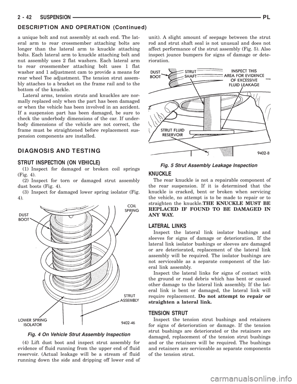
(1) Inspect for damaged or broken coil springs
(Fig. 4).
(2) Inspect for torn or damaged strut assembly
dust boots (Fig. 4).
(3) Inspect for damaged lower spring isolator (Fig.
4).
(4) Lift dust boot and inspect strut assembly for
evidence of fluid running from the upper end of fluid
reservoir. (Actual leakage will be a stream of fluid
running down the side and dripping off lower end ofunit). A slight amount of seepage between the strut
rod and strut shaft seal is not unusual and does not
affect performance of the strut assembly (Fig. 5). Also
inspect jounce bumpers for signs of damage or dete-
rioration.
KNUCKLE
The rear knuckle is not a repairable component of
the rear suspension. If it is determined that the
knuckle is cracked, bent or broken when servicing
the vehicle, no attempt is to be made to repair or to
straighten the knuckle.THE KNUCKLE MUST BE
REPLACED IF FOUND TO BE DAMAGED IN
ANY WAY.
LATERAL LINKS
Inspect the lateral link isolator bushings and
sleeves for signs of damage or deterioration. If the
lateral link isolator bushings or sleeves are damaged
or are deteriorated, replacement of the lateral link
assembly will be required. The isolator bushings are
not serviceable as a separate component of the lat-
eral link assembly.
Inspect the lateral links for signs of contact with
the ground or road debris which has bent or caused
other damage to the lateral link assembly. If the lat-
eral link is bent or damaged, the lateral link will
require replacement.Do not attempt to repair or
straighten a lateral link.
TENSION STRUT
Inspect the tension strut bushings and retainers
for signs of deterioration or damage. If the tension
strut bushings are deteriorated or the retainers are
damaged, replacement of the tension strut bushings
and or the retainers will be required. The bushings
and retainers are serviceable as separate components
of the tension strut.
Fig. 4 On Vehicle Strut Assembly Inspection
Fig. 5 Strut Assembly Leakage Inspection
2 - 42 SUSPENSIONPL
DESCRIPTION AND OPERATION (Continued)
Page 95 of 1200
DRUM BRAKE AUTOMATIC ADJUSTER
Place the vehicle on a hoist with a helper in the
driver's seat to apply the brakes. Remove the access
plug from the rear adjustment slot in each brake
support plate to provide access to the adjuster star
wheel. Then, to eliminate the possibility of maximum
adjustment, back the star wheel off approximately 10
notches. It will be necessary to hold the adjuster
lever away from the star wheel to permit this adjust-
ment.
Apply the brake pedal. This application of force
will cause the brake shoes to leave the anchor. Upon
application of the brake pedal, the lever should move
downward, turning the star wheel. Thus, a definite
rotation of the adjuster star wheel can be observed if
the automatic adjuster is working properly. If one or
more adjusters do not function properly, the respec-
tive drum must be removed for adjuster servicing.
ROTOR THICKNESS AND RUNOUT
Any servicing of the rotor requires extreme care to
maintain the rotor within service tolerances to
ensure proper brake action.
Before refinishing or refacing a rotor, the disc
should be checked and inspected for the following
conditions:
Braking surface scoring, rust, impregnation of lin-
ing material and worn ridges.
Excessive lateral runout or wobble.
Thickness variation (Parallelism).
Dishing or distortion (Flatness).
If a vehicle has not been driven for a period of
time, the rotor surface will rust in the area not cov-
ered by the brake lining and cause noise and chatter
when the brakes are applied.
Excessive wear and scoring of the rotor can cause
temporary improper lining contact if ridges are not
removed before installation of new brake pad assem-
blies.
Some discoloration or wear of the rotor surface is
normal and does not require resurfacing when lin-
ings are replaced.
Excessive runout or wobble in a rotor can increase
pedal travel due to piston knock back. This will
increase guide pin sleeve wear due to tendency of cal-
iper to follow rotor wobble.
Thickness variation in a rotor can also result in
pedal pulsation, chatter and surge due to variation in
brake output. This can also be caused by excessive
runout in rotor or hub.
Dishing or distortion can be caused by extreme
heat and abuse of the brakes.
ROTOR RUNOUT AND THICKNESS VARIATION
On vehicle rotor runout is the combination of the
individual runout of the hub face and the runout ofthe rotor. (The hub and rotor runouts are separable).
To measure runout on the vehicle, remove the wheel
and reinstall the lug nuts tightening the rotor to the
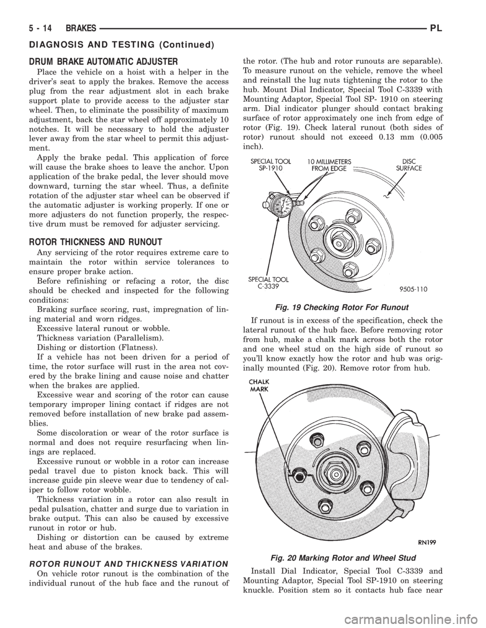
hub. Mount Dial Indicator, Special Tool C-3339 with
Mounting Adaptor, Special Tool SP- 1910 on steering
arm. Dial indicator plunger should contact braking
surface of rotor approximately one inch from edge of
rotor (Fig. 19). Check lateral runout (both sides of
rotor) runout should not exceed 0.13 mm (0.005
inch).
If runout is in excess of the specification, check the
lateral runout of the hub face. Before removing rotor
from hub, make a chalk mark across both the rotor
and one wheel stud on the high side of runout so
you'll know exactly how the rotor and hub was orig-
inally mounted (Fig. 20). Remove rotor from hub.
Install Dial Indicator, Special Tool C-3339 and
Mounting Adaptor, Special Tool SP-1910 on steering
knuckle. Position stem so it contacts hub face near
Fig. 19 Checking Rotor For Runout
Fig. 20 Marking Rotor and Wheel Stud
5 - 14 BRAKESPL
DIAGNOSIS AND TESTING (Continued)
Page 337 of 1200
LICENSE PLATE LAMP BULB
REMOVAL
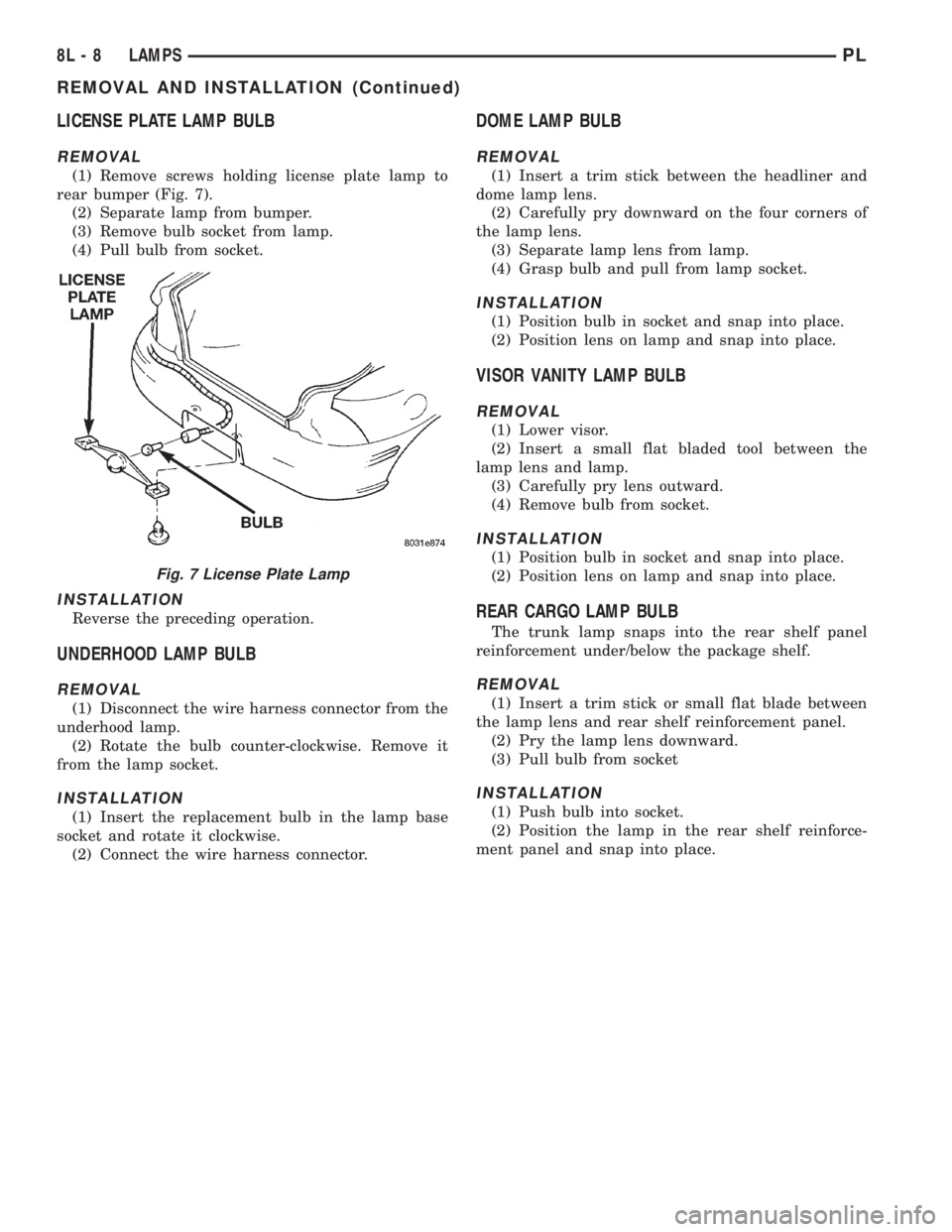
(1) Remove screws holding license plate lamp to
rear bumper (Fig. 7).
(2) Separate lamp from bumper.
(3) Remove bulb socket from lamp.
(4) Pull bulb from socket.
INSTALLATION
Reverse the preceding operation.
UNDERHOOD LAMP BULB
REMOVAL
(1) Disconnect the wire harness connector from the
underhood lamp.
(2) Rotate the bulb counter-clockwise. Remove it
from the lamp socket.
INSTALLATION
(1) Insert the replacement bulb in the lamp base
socket and rotate it clockwise.
(2) Connect the wire harness connector.
DOME LAMP BULB
REMOVAL
(1) Insert a trim stick between the headliner and
dome lamp lens.
(2) Carefully pry downward on the four corners of
the lamp lens.
(3) Separate lamp lens from lamp.
(4) Grasp bulb and pull from lamp socket.
INSTALLATION
(1) Position bulb in socket and snap into place.
(2) Position lens on lamp and snap into place.
VISOR VANITY LAMP BULB
REMOVAL
(1) Lower visor.
(2) Insert a small flat bladed tool between the
lamp lens and lamp.
(3) Carefully pry lens outward.
(4) Remove bulb from socket.
INSTALLATION
(1) Position bulb in socket and snap into place.
(2) Position lens on lamp and snap into place.
REAR CARGO LAMP BULB
The trunk lamp snaps into the rear shelf panel
reinforcement under/below the package shelf.
REMOVAL
(1) Insert a trim stick or small flat blade between
the lamp lens and rear shelf reinforcement panel.
(2) Pry the lamp lens downward.
(3) Pull bulb from socket
INSTALLATION
(1) Push bulb into socket.
(2) Position the lamp in the rear shelf reinforce-
ment panel and snap into place.
Fig. 7 License Plate Lamp
8L - 8 LAMPSPL
REMOVAL AND INSTALLATION (Continued)
Page 354 of 1200
DIAGNOSIS AND TESTING
AIRBAG SYSTEM TEST
(1) Disconnect and isolate the negative battery
cable.
(2) Connect scan tool (DRB) to Data Link connec-
tor, located at right side of the steering column and
at the lower edge of the lower instrument panel.
(3) Turn the ignition key to ON position. Exit vehi-
cle with scan tool. Use the latest version of the
proper cartridge.
(4) After checking that no one is inside the vehicle,
connect the battery negative terminal.
(5) Using the scan tool, read and record active
diagnostic code data.
(6) Read and record any stored diagnostic codes.
(7) Refer to the Passive Restraint Diagnostic Test
Manual if any diagnostic codes are found in Step 5 or
Step 6.
(8) Erase stored diagnostic codes if there are no
active diagnostic codes. If problems remain, diagnos-
tic codes will not erase. Refer to the Passive
Restraint Diagnostic Test Manual to diagnose the
problem.If the airbag warning lamp either fails
to light with the ignition switch on, or the light
goes on and stays on, there is a system malfunc-
tion. Refer to the Passive Restraint Diagnostic
Test Manual to diagnose the problem.
SERVICE PROCEDURES
CLEANUP PROCEDURE
Roll or fold the passenger airbag towards the
instrument panel surface and close the door over the
folded bag. Then tape the door shut.
Use a vacuum cleaner to remove any residual pow-
der from the vehicle interior. Work from the outside
in to avoid kneeling or sitting in a contaminated
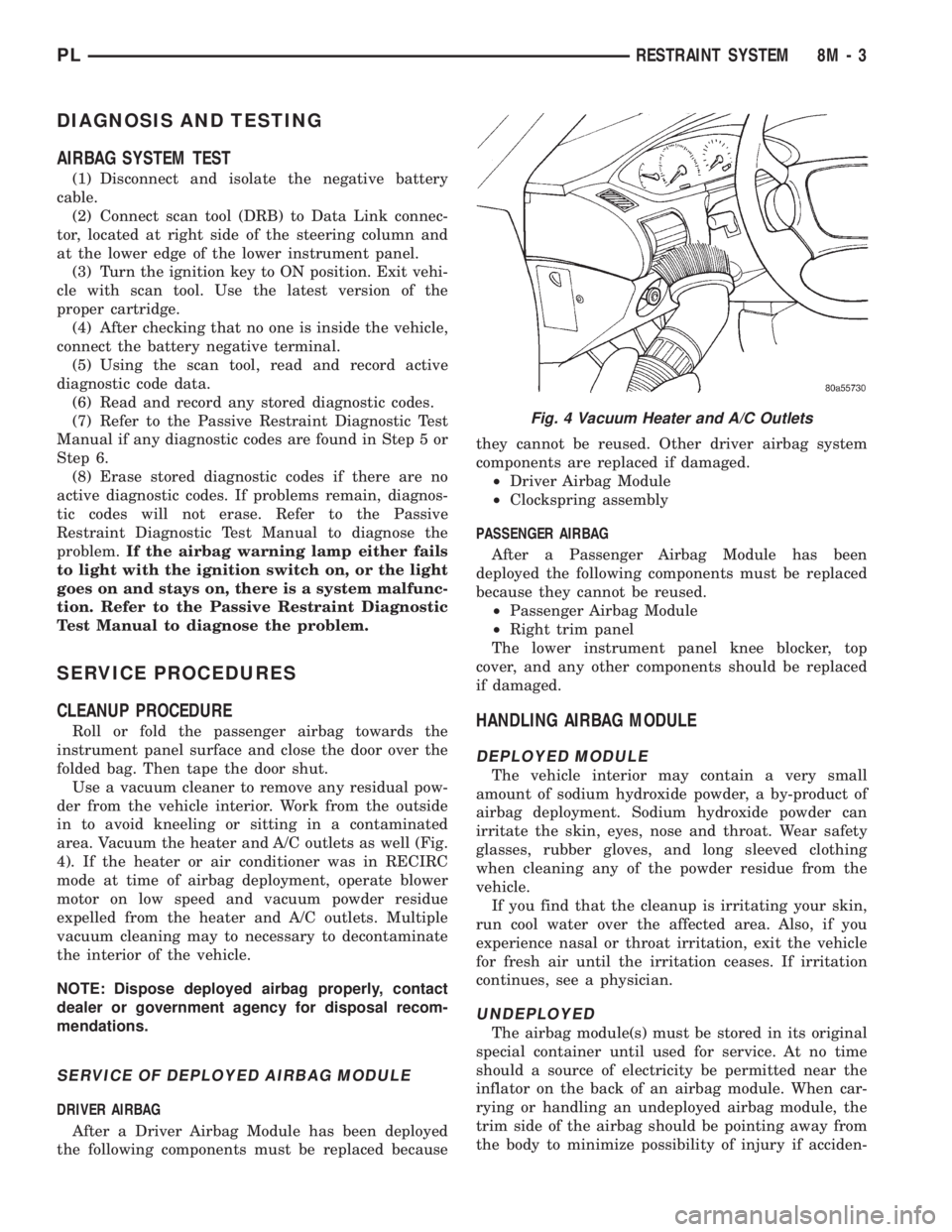
area. Vacuum the heater and A/C outlets as well (Fig.
4). If the heater or air conditioner was in RECIRC
mode at time of airbag deployment, operate blower
motor on low speed and vacuum powder residue
expelled from the heater and A/C outlets. Multiple
vacuum cleaning may to necessary to decontaminate
the interior of the vehicle.
NOTE: Dispose deployed airbag properly, contact
dealer or government agency for disposal recom-
mendations.
SERVICE OF DEPLOYED AIRBAG MODULE
DRIVER AIRBAG
After a Driver Airbag Module has been deployed
the following components must be replaced becausethey cannot be reused. Other driver airbag system
components are replaced if damaged.
²Driver Airbag Module
²Clockspring assembly
PASSENGER AIRBAG
After a Passenger Airbag Module has been
deployed the following components must be replaced
because they cannot be reused.
²Passenger Airbag Module
²Right trim panel
The lower instrument panel knee blocker, top
cover, and any other components should be replaced
if damaged.
HANDLING AIRBAG MODULE
DEPLOYED MODULE
The vehicle interior may contain a very small
amount of sodium hydroxide powder, a by-product of
airbag deployment. Sodium hydroxide powder can
irritate the skin, eyes, nose and throat. Wear safety
glasses, rubber gloves, and long sleeved clothing
when cleaning any of the powder residue from the
vehicle.
If you find that the cleanup is irritating your skin,
run cool water over the affected area. Also, if you
experience nasal or throat irritation, exit the vehicle
for fresh air until the irritation ceases. If irritation
continues, see a physician.
UNDEPLOYED
The airbag module(s) must be stored in its original
special container until used for service. At no time
should a source of electricity be permitted near the
inflator on the back of an airbag module. When car-
rying or handling an undeployed airbag module, the
trim side of the airbag should be pointing away from
the body to minimize possibility of injury if acciden-
Fig. 4 Vacuum Heater and A/C Outlets
PLRESTRAINT SYSTEM 8M - 3
Page 734 of 1200
(8) Install A/C compressor and hoses. Refer to
Group 24, Heater and Air Conditioning for procedure.
(9) Install accessory drive belts. Refer to Group 7,
Cooling System Accessory Drive Section for belt ten-
sion adjustment.
(10) Install front engine mount. Refer to this sec-
tion for procedure.
(11) Manual transmission: Install power hop
damper.
(12) Install inner splash shield. Install wheels and
tires.
(13)Manual Transmission:Connect clutch cable
and linkages. Refer to Group 6, Manual Transaxle
Clutch.
(14)Automatic Transmission:Connect shifter
and kickdown linkage. Refer to Group 21, Transaxle
for procedures.
(15) Connect fuel line and heater hoses.
(16) Install ground straps. Connect engine and
throttle body connections and harnesses. Refer to
Group 8, Electrical for procedure.
(17) Connect throttle body linkage. Refer to Group
14, Fuel System for procedure.
(18) Install radiator and shroud assembly. Install
radiator hoses. Fill cooling system. Refer to Group 7,
Cooling System for filling procedure.
(19) Install battery tray and battery. Set Power-
train Control Module (PCM) into place.
(20) Install air cleaner and hoses.
(21) Install oil filter. Fill engine crankcase with
proper oil to correct level.
(22) Perform camshaft and crankshaft timing
relearn procedure as follows:
²Connect the DRB scan tool to the data link
(diagnostic) connector. This connector is located in
the passenger compartment; at the lower edge of
instrument panel; near the steering column.
²Turn the ignition switch on and access the ªmis-
cellaneousº screen.
²Select ªre-learn cam/crankº option and follow
directions on DRB screen.
(23) Start engine and run until operating temper-
ature is reached.
(24) Adjust transmission linkage, if necessary.
CYLINDER HEAD COVER
REMOVAL
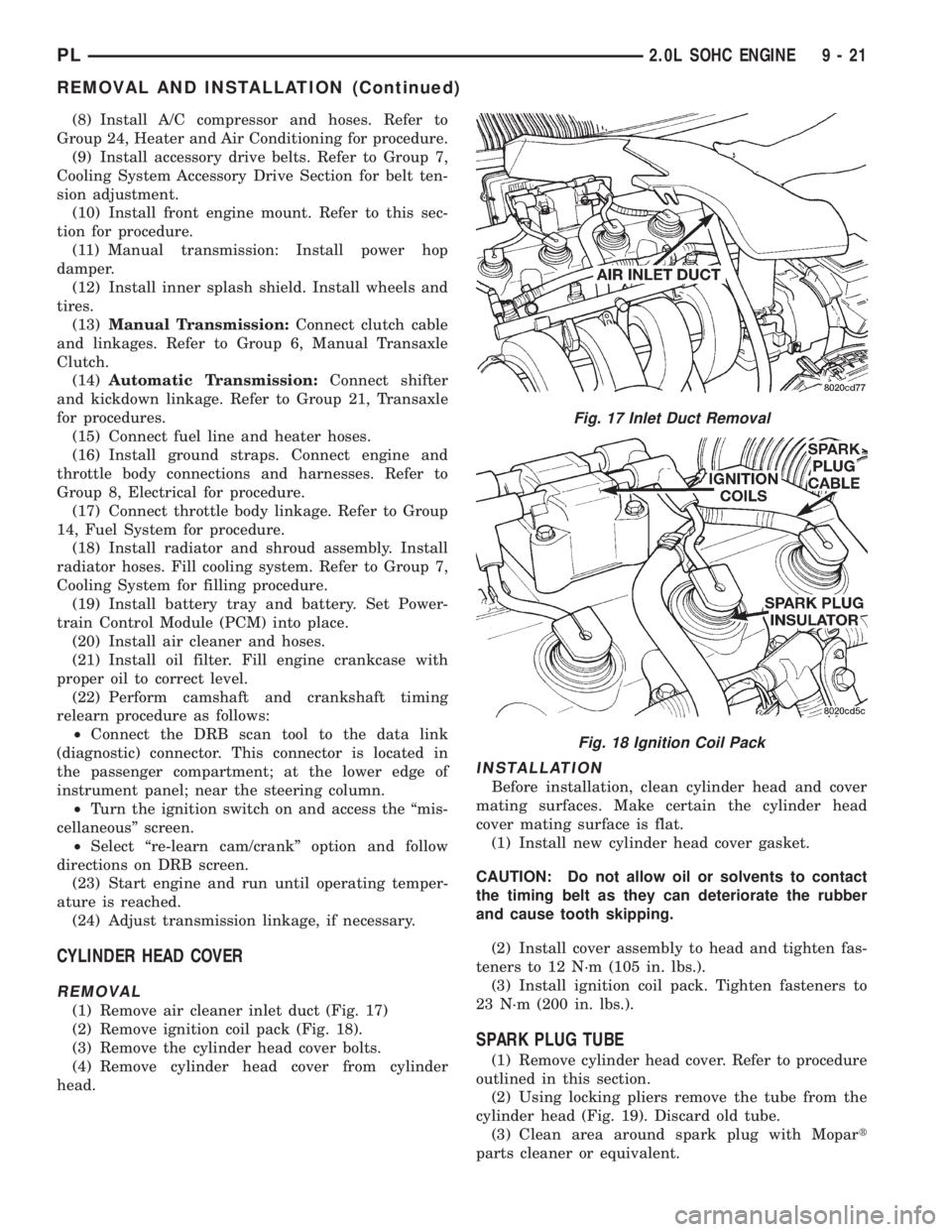
(1) Remove air cleaner inlet duct (Fig. 17)
(2) Remove ignition coil pack (Fig. 18).
(3) Remove the cylinder head cover bolts.
(4) Remove cylinder head cover from cylinder
head.
INSTALLATION
Before installation, clean cylinder head and cover
mating surfaces. Make certain the cylinder head
cover mating surface is flat.
(1) Install new cylinder head cover gasket.
CAUTION: Do not allow oil or solvents to contact
the timing belt as they can deteriorate the rubber
and cause tooth skipping.
(2) Install cover assembly to head and tighten fas-
teners to 12 N´m (105 in. lbs.).
(3) Install ignition coil pack. Tighten fasteners to
23 N´m (200 in. lbs.).
SPARK PLUG TUBE
(1) Remove cylinder head cover. Refer to procedure
outlined in this section.
(2) Using locking pliers remove the tube from the
cylinder head (Fig. 19). Discard old tube.
(3) Clean area around spark plug with Mopart
parts cleaner or equivalent.
Fig. 17 Inlet Duct Removal
Fig. 18 Ignition Coil Pack
PL2.0L SOHC ENGINE 9 - 21
REMOVAL AND INSTALLATION (Continued)
Page 780 of 1200
²Select ªre-learn cam/crankº option and follow
directions on DRB screen.
(23) Start engine and run until operating temper-
ature is reached.
(24) Adjust transmission linkage, if necessary.
CYLINDER HEAD COVER
REMOVAL
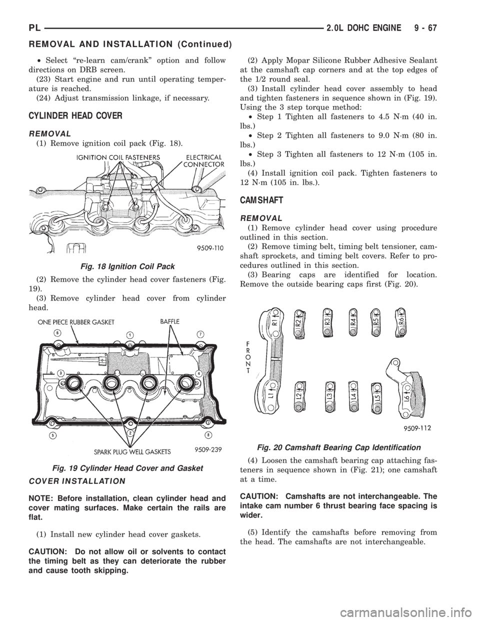
(1) Remove ignition coil pack (Fig. 18).
(2) Remove the cylinder head cover fasteners (Fig.
19).
(3) Remove cylinder head cover from cylinder
head.
COVER INSTALLATION
NOTE: Before installation, clean cylinder head and
cover mating surfaces. Make certain the rails are
flat.
(1) Install new cylinder head cover gaskets.
CAUTION: Do not allow oil or solvents to contact
the timing belt as they can deteriorate the rubber
and cause tooth skipping.(2) Apply Mopar Silicone Rubber Adhesive Sealant
at the camshaft cap corners and at the top edges of
the 1/2 round seal.
(3) Install cylinder head cover assembly to head
and tighten fasteners in sequence shown in (Fig. 19).
Using the 3 step torque method:
²Step 1 Tighten all fasteners to 4.5 N´m (40 in.
lbs.)
²Step 2 Tighten all fasteners to 9.0 N´m (80 in.
lbs.)
²Step 3 Tighten all fasteners to 12 N´m (105 in.
lbs.)
(4) Install ignition coil pack. Tighten fasteners to
12 N´m (105 in. lbs.).
CAMSHAFT
REMOVAL
(1) Remove cylinder head cover using procedure
outlined in this section.
(2) Remove timing belt, timing belt tensioner, cam-
shaft sprockets, and timing belt covers. Refer to pro-
cedures outlined in this section.
(3) Bearing caps are identified for location.
Remove the outside bearing caps first (Fig. 20).
(4) Loosen the camshaft bearing cap attaching fas-
teners in sequence shown in (Fig. 21); one camshaft
at a time.
CAUTION: Camshafts are not interchangeable. The
intake cam number 6 thrust bearing face spacing is
wider.
(5) Identify the camshafts before removing from
the head. The camshafts are not interchangeable.
Fig. 18 Ignition Coil Pack
Fig. 19 Cylinder Head Cover and Gasket
Fig. 20 Camshaft Bearing Cap Identification
PL2.0L DOHC ENGINE 9 - 67
REMOVAL AND INSTALLATION (Continued)
Page 905 of 1200
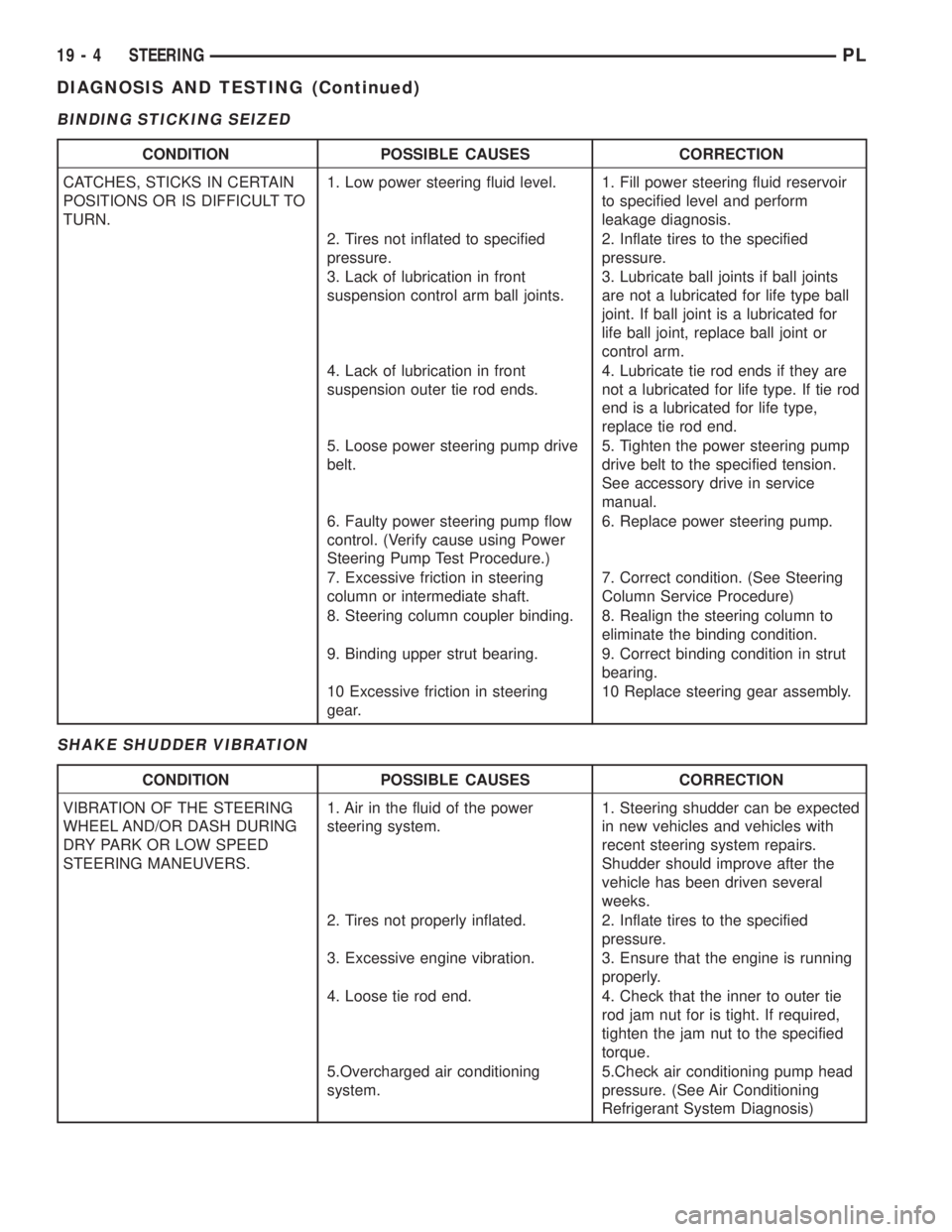
BINDING STICKING SEIZED
SHAKE SHUDDER VIBRATION
CONDITION POSSIBLE CAUSES CORRECTION
CATCHES, STICKS IN CERTAIN
POSITIONS OR IS DIFFICULT TO
TURN.1. Low power steering fluid level. 1. Fill power steering fluid reservoir
to specified level and perform
leakage diagnosis.
2. Tires not inflated to specified
pressure.2. Inflate tires to the specified
pressure.
3. Lack of lubrication in front
suspension control arm ball joints.3. Lubricate ball joints if ball joints
are not a lubricated for life type ball
joint. If ball joint is a lubricated for
life ball joint, replace ball joint or
control arm.
4. Lack of lubrication in front
suspension outer tie rod ends.4. Lubricate tie rod ends if they are
not a lubricated for life type. If tie rod
end is a lubricated for life type,
replace tie rod end.
5. Loose power steering pump drive
belt.5. Tighten the power steering pump
drive belt to the specified tension.
See accessory drive in service
manual.
6. Faulty power steering pump flow
control. (Verify cause using Power
Steering Pump Test Procedure.)6. Replace power steering pump.
7. Excessive friction in steering
column or intermediate shaft.7. Correct condition. (See Steering
Column Service Procedure)
8. Steering column coupler binding. 8. Realign the steering column to
eliminate the binding condition.
9. Binding upper strut bearing. 9. Correct binding condition in strut
bearing.
10 Excessive friction in steering
gear.10 Replace steering gear assembly.
CONDITION POSSIBLE CAUSES CORRECTION
VIBRATION OF THE STEERING
WHEEL AND/OR DASH DURING
DRY PARK OR LOW SPEED
STEERING MANEUVERS.1. Air in the fluid of the power
steering system.1. Steering shudder can be expected
in new vehicles and vehicles with
recent steering system repairs.
Shudder should improve after the
vehicle has been driven several
weeks.
2. Tires not properly inflated. 2. Inflate tires to the specified
pressure.
3. Excessive engine vibration. 3. Ensure that the engine is running
properly.
4. Loose tie rod end. 4. Check that the inner to outer tie
rod jam nut for is tight. If required,
tighten the jam nut to the specified
torque.
5.Overcharged air conditioning
system.5.Check air conditioning pump head
pressure. (See Air Conditioning
Refrigerant System Diagnosis)
19 - 4 STEERINGPL
DIAGNOSIS AND TESTING (Continued)