1999 DODGE NEON driver seat adjustment
[x] Cancel search: driver seat adjustmentPage 95 of 1200

DRUM BRAKE AUTOMATIC ADJUSTER
Place the vehicle on a hoist with a helper in the
driver's seat to apply the brakes. Remove the access
plug from the rear adjustment slot in each brake
support plate to provide access to the adjuster star
wheel. Then, to eliminate the possibility of maximum
adjustment, back the star wheel off approximately 10
notches. It will be necessary to hold the adjuster
lever away from the star wheel to permit this adjust-
ment.
Apply the brake pedal. This application of force
will cause the brake shoes to leave the anchor. Upon
application of the brake pedal, the lever should move
downward, turning the star wheel. Thus, a definite
rotation of the adjuster star wheel can be observed if
the automatic adjuster is working properly. If one or
more adjusters do not function properly, the respec-
tive drum must be removed for adjuster servicing.
ROTOR THICKNESS AND RUNOUT
Any servicing of the rotor requires extreme care to
maintain the rotor within service tolerances to
ensure proper brake action.
Before refinishing or refacing a rotor, the disc
should be checked and inspected for the following
conditions:
Braking surface scoring, rust, impregnation of lin-
ing material and worn ridges.
Excessive lateral runout or wobble.
Thickness variation (Parallelism).
Dishing or distortion (Flatness).
If a vehicle has not been driven for a period of
time, the rotor surface will rust in the area not cov-
ered by the brake lining and cause noise and chatter
when the brakes are applied.
Excessive wear and scoring of the rotor can cause
temporary improper lining contact if ridges are not
removed before installation of new brake pad assem-
blies.
Some discoloration or wear of the rotor surface is
normal and does not require resurfacing when lin-
ings are replaced.
Excessive runout or wobble in a rotor can increase
pedal travel due to piston knock back. This will
increase guide pin sleeve wear due to tendency of cal-
iper to follow rotor wobble.
Thickness variation in a rotor can also result in
pedal pulsation, chatter and surge due to variation in
brake output. This can also be caused by excessive
runout in rotor or hub.
Dishing or distortion can be caused by extreme
heat and abuse of the brakes.
ROTOR RUNOUT AND THICKNESS VARIATION
On vehicle rotor runout is the combination of the
individual runout of the hub face and the runout ofthe rotor. (The hub and rotor runouts are separable).
To measure runout on the vehicle, remove the wheel
and reinstall the lug nuts tightening the rotor to the
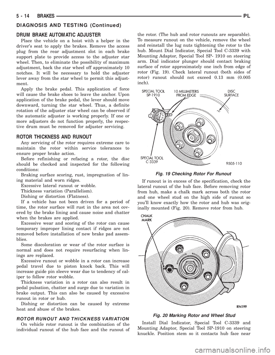
hub. Mount Dial Indicator, Special Tool C-3339 with
Mounting Adaptor, Special Tool SP- 1910 on steering
arm. Dial indicator plunger should contact braking
surface of rotor approximately one inch from edge of
rotor (Fig. 19). Check lateral runout (both sides of
rotor) runout should not exceed 0.13 mm (0.005
inch).
If runout is in excess of the specification, check the
lateral runout of the hub face. Before removing rotor
from hub, make a chalk mark across both the rotor
and one wheel stud on the high side of runout so
you'll know exactly how the rotor and hub was orig-
inally mounted (Fig. 20). Remove rotor from hub.
Install Dial Indicator, Special Tool C-3339 and
Mounting Adaptor, Special Tool SP-1910 on steering
knuckle. Position stem so it contacts hub face near
Fig. 19 Checking Rotor For Runout
Fig. 20 Marking Rotor and Wheel Stud
5 - 14 BRAKESPL
DIAGNOSIS AND TESTING (Continued)
Page 115 of 1200

or fluid leak is visible, disassemble caliper and
install a new seal and boot, (and piston if scored).
Refer to Caliper Disassembly And Re-Assembly Pro-
cedures in Disc Brake Caliper Service in this section
of the service manual.
Check the caliper dust boot and caliper pin bush-
ings to determine if they are in good condition.
Replace if they are damaged, dry, or found to be brit-
tle. Refer to Guide Pin Bushing Service in Disc
Brake Caliper Service in this section of the service
manual.
INSTALL
(1) Completely retract the caliper piston back into
the piston bore of the caliper assembly. This is
required for caliper installation when new brake pad
assemblies are installed on caliper.
(2) Lubricate both adapter abutments with a lib-
eral amount of MopartMultipurpose Lubricant, or
equivalent.
(3) Install rear rotor on the hub making sure it is
squarely seated on face of hub (Fig. 77).
(4) Remove protective paper from noise suppres-
sion gasket on both inner and outer brake pad
assemblies (if equipped).
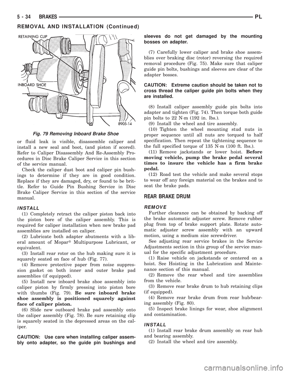
(5) Install new inboard brake shoe assembly into
caliper piston by firmly pressing into piston bore
with thumbs (Fig. 79).Be sure inboard brake
shoe assembly is positioned squarely against
face of caliper piston.
(6) Slide new outboard brake pad assembly onto
the caliper assembly (Fig. 78). Be sure retaining clip
is squarely seated in the depressed areas on the cal-
iper.
CAUTION: Use care when installing caliper assem-
bly onto adapter, so the guide pin bushings andsleeves do not get damaged by the mounting
bosses on adapter.
(7) Carefully lower caliper and brake shoe assem-
blies over braking disc (rotor) reversing the required
removal procedure (Fig. 75). Make sure that caliper
guide pin bolts, bushings and sleeves are clear of the
adapter bosses.
CAUTION: Extreme caution should be taken not to
cross thread the caliper guide pin bolts when they
are installed.
(8) Install caliper assembly guide pin bolts into
adapter and tighten (Fig. 74). Then torque both guide
pin bolts to 22 N´m (192 in. lbs.).
(9) Install the wheel and tire assembly.
(10) Tighten the wheel mounting stud nuts in
proper sequence until all nuts are torqued to half
specification. Then repeat the tightening sequence to
the full specified torque of 135 N´m (100 ft. lbs.).
(11) Remove jackstands or lower hoist.Before
moving vehicle, pump the brake pedal several
times to insure the vehicle has a firm brake
pedal.
(12) Road test the vehicle and make several stops
to wear off any foreign material on the brakes and to
seat the brake pads.
REAR BRAKE DRUM
REMOVE
Further clearance can be obtained by backing off
the brake automatic adjuster screw. Remove rubber
plug from top of brake support plate. Rotate auto-
matic adjuster screw assembly with an upward
motion, using a medium size screwdriver.
See adjusting rear service brakes in the Service
Adjustments section in this group of the service man-
ual for the specific adjustment procedure.
(1) Raise vehicle on jackstands or centered on a
hoist. See Hoisting in the Lubrication and Mainte-
nance section of this manual.
(2) Remove the rear wheel and tire assemblies
from the vehicle.
(3) Remove rear brake drum to hub retaining clips
(if equipped).
(4) Remove rear brake drum from rear hub/bear-
ing assembly (Fig. 80).
(5) Inspect brake linings for wear, shoe alignment
and contamination.
INSTALL
(1) Install rear brake drum assembly on rear hub
and bearing assembly.
(2) Install the wheel and tire assembly.
Fig. 79 Removing Inboard Brake Shoe
5 - 34 BRAKESPL
REMOVAL AND INSTALLATION (Continued)