1999 DODGE NEON boot
[x] Cancel search: bootPage 19 of 1200
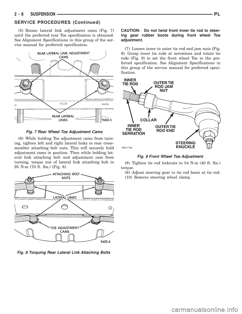
(5) Rotate lateral link adjustment cams (Fig. 7)
until the preferred rear Toe specification is obtained.
See Alignment Specifications in this group of the ser-
vice manual for preferred specification.
(6) While holding Toe adjustment cams from turn-
ing, tighten left and right lateral links to rear cross-
member attaching bolt nuts. This will securely hold
adjustment cams in position. Then while holding lat-
eral link attaching bolt and adjustment cam from
turning, torque nut of lateral link attaching bolt to
95 N´m (70 ft. lbs.) (Fig. 8).CAUTION: Do not twist front inner tie rod to steer-
ing gear rubber boots during front wheel Toe
adjustment.
(7) Loosen inner to outer tie rod end jam nuts (Fig.
9). Grasp inner tie rods at serrations and rotate tie
rods (Fig. 9) to set the front wheel Toe to the pre-
ferred specification. See Alignment Specifications in
this group of the service manual for preferred speci-
fication.
(8) Tighten tie rod locknuts to 54 N´m (40 ft. lbs.)
torque.
(9) Adjust steering gear to tie rod boots at tie rod.
(10) Remove steering wheel clamp.
Fig. 7 Rear Wheel Toe Adjustment Cams
Fig. 8 Torquing Rear Lateral Link Attaching Bolts
Fig. 9 Front Wheel Toe Adjustment
2 - 8 SUSPENSIONPL
SERVICE PROCEDURES (Continued)
Page 26 of 1200
Use the procedure and special tools shown in the
service procedures section for the wheel mounting
studs when replacing the wheel attaching studs.
The hub and bearing assembly does not require
removal from the steering knuckle or the rear
knuckle to replace the wheel attaching studs in the
hub and bearing assembly.
DIAGNOSIS AND TESTING
MCPHERSON STRUT ASSEMBLY
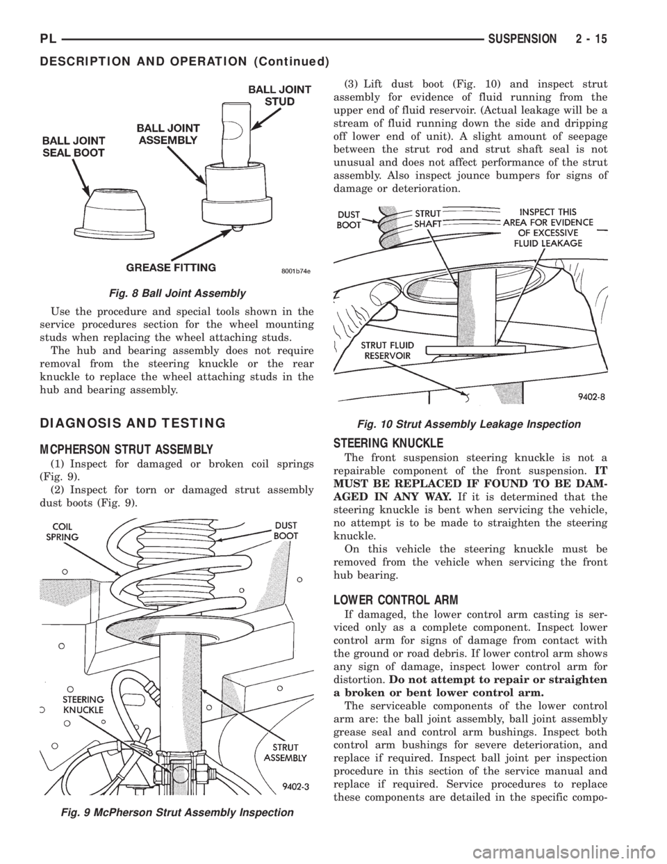
(1) Inspect for damaged or broken coil springs
(Fig. 9).
(2) Inspect for torn or damaged strut assembly
dust boots (Fig. 9).(3) Lift dust boot (Fig. 10) and inspect strut
assembly for evidence of fluid running from the
upper end of fluid reservoir. (Actual leakage will be a
stream of fluid running down the side and dripping
off lower end of unit). A slight amount of seepage
between the strut rod and strut shaft seal is not
unusual and does not affect performance of the strut
assembly. Also inspect jounce bumpers for signs of
damage or deterioration.
STEERING KNUCKLE
The front suspension steering knuckle is not a
repairable component of the front suspension.IT
MUST BE REPLACED IF FOUND TO BE DAM-
AGED IN ANY WAY.If it is determined that the
steering knuckle is bent when servicing the vehicle,
no attempt is to be made to straighten the steering
knuckle.
On this vehicle the steering knuckle must be
removed from the vehicle when servicing the front
hub bearing.
LOWER CONTROL ARM
If damaged, the lower control arm casting is ser-
viced only as a complete component. Inspect lower
control arm for signs of damage from contact with
the ground or road debris. If lower control arm shows
any sign of damage, inspect lower control arm for
distortion.Do not attempt to repair or straighten
a broken or bent lower control arm.
The serviceable components of the lower control
arm are: the ball joint assembly, ball joint assembly
grease seal and control arm bushings. Inspect both
control arm bushings for severe deterioration, and
replace if required. Inspect ball joint per inspection
procedure in this section of the service manual and
replace if required. Service procedures to replace
these components are detailed in the specific compo-
Fig. 8 Ball Joint Assembly
Fig. 9 McPherson Strut Assembly Inspection
Fig. 10 Strut Assembly Leakage Inspection
PLSUSPENSION 2 - 15
DESCRIPTION AND OPERATION (Continued)
Page 43 of 1200

²Binding strut assembly pivot bearing. If pivot
bearing is replaced it is to be installed with the white
side of bearing facing up (Fig. 74).
²Inspect dust shield for rips and/or deterioration.
²Inspect jounce bumper for cracks and signs of
deterioration.
(11) Replace any components of the strut assembly
found to be worn or defective during the inspection,
before assembling the strut.
ASSEMBLE
(1) Clamp the strut assembly in a vise, with the
strut in a vertical position.When clamping the
strut assembly in the vise, do not clamp strut
using the body of the strut only by strut clevis
bracket (Fig. 67).
(2) Install the compressed coil spring onto the
strut. Coil spring is to be installed with smaller coil
down, so spring correctly seats on strut assembly
(Fig. 73).
(3) Install jounce bumper on the strut shaft (Fig.
72).
(4) Install dust shield, pivot bearing and upper
spring seat as an assembly on the strut (Fig. 71).
(5) Position upper spring seat alignment notch
with clevis bracket on strut assembly.
(6) Install strut mount on strut assembly (Fig. 70)
and the strut mount retaining nut on the shaft of the
strut assembly.
WARNING: THE FOLLOWING 2 STEPS MUST BE
COMPLETELY DONE BEFORE SPRING COMPRES-
SOR, SPECIAL TOOL C-4838 IS RELEASED FROM
THE COIL SPRING.
(7) Install Socket, Strut Nut, Special Tool L-4558A
(or L-4558) on the strut shaft retaining nut (Fig. 69).
Then install a 10 mm socket through the center of
the socket and on the hex of the strut shaft (Fig. 69).
While holding strut shaft from turning, torque strut
shaft retaining nut to 75 N´m (55 ft. lbs.).
(8) Equally loosen both Spring Compressors, Spe-
cial Tool C-4838 until top coil of spring is fully seated
against upper spring seat and strut mount. Then
relieve all tension from spring compressors and
remove spring compressors from strut assembly
spring.
BALL JOINT
DISASSEMBLE
(1) Using a screw driver or other suitable tool, pry
seal boot off of ball joint assembly (Fig. 75).
(2) Position Receiving Cup, Special Tool 6758 to
support lower control arm while receiving ball joint
assembly (Fig. 76). Install Remover/Installer, Special
Tool 6804 in top of ball joint assembly (Fig. 76).(3) Using arbor press, press ball joint assembly
completely out of lower control arm.
ASSEMBLE
CAUTION: When installing ball joint in its mount-
ing hole in lower control arm, position ball joint so
notch in ball joint stud is facing the front lower con-
trol arm bushing. This will ease assembly of ball
joint to steering knuckle when attempting to install
pinch bolt.
(1) By hand, position ball joint assembly into ball
joint bore of lower control arm. Be sure ball joint
assembly is not cocked in the bore of the control arm,
this will cause binding of the ball joint assembly,
when being pressed into lower control arm.
(2) Position assembly in an arbor press with
Receiving Cup, Special Tool 6758 supporting lower
control arm (Fig. 77). Then install Remover/Installer,
Special Tool 6804 on the bottom of the ball joint
assembly (Fig. 77).
Fig. 75 Ball Joint Seal Boot Removal
Fig. 76 Removing Ball Joint From Lower Control
Arm
2 - 32 SUSPENSIONPL
DISASSEMBLY AND ASSEMBLY (Continued)
Page 44 of 1200
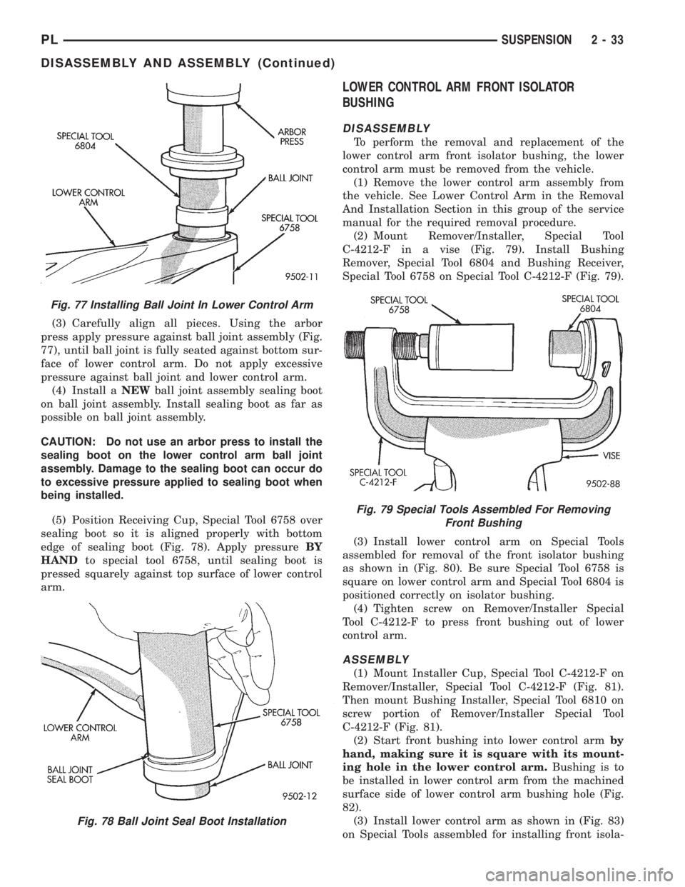
(3) Carefully align all pieces. Using the arbor
press apply pressure against ball joint assembly (Fig.
77), until ball joint is fully seated against bottom sur-
face of lower control arm. Do not apply excessive
pressure against ball joint and lower control arm.
(4) Install aNEWball joint assembly sealing boot
on ball joint assembly. Install sealing boot as far as
possible on ball joint assembly.
CAUTION: Do not use an arbor press to install the
sealing boot on the lower control arm ball joint
assembly. Damage to the sealing boot can occur do
to excessive pressure applied to sealing boot when
being installed.
(5) Position Receiving Cup, Special Tool 6758 over
sealing boot so it is aligned properly with bottom
edge of sealing boot (Fig. 78). Apply pressureBY
HANDto special tool 6758, until sealing boot is
pressed squarely against top surface of lower control
arm.
LOWER CONTROL ARM FRONT ISOLATOR
BUSHING
DISASSEMBLY
To perform the removal and replacement of the
lower control arm front isolator bushing, the lower
control arm must be removed from the vehicle.
(1) Remove the lower control arm assembly from
the vehicle. See Lower Control Arm in the Removal
And Installation Section in this group of the service
manual for the required removal procedure.
(2) Mount Remover/Installer, Special Tool
C-4212-F in a vise (Fig. 79). Install Bushing
Remover, Special Tool 6804 and Bushing Receiver,
Special Tool 6758 on Special Tool C-4212-F (Fig. 79).
(3) Install lower control arm on Special Tools
assembled for removal of the front isolator bushing
as shown in (Fig. 80). Be sure Special Tool 6758 is
square on lower control arm and Special Tool 6804 is
positioned correctly on isolator bushing.
(4) Tighten screw on Remover/Installer Special
Tool C-4212-F to press front bushing out of lower
control arm.
ASSEMBLY
(1) Mount Installer Cup, Special Tool C-4212-F on
Remover/Installer, Special Tool C-4212-F (Fig. 81).
Then mount Bushing Installer, Special Tool 6810 on
screw portion of Remover/Installer Special Tool
C-4212-F (Fig. 81).
(2) Start front bushing into lower control armby
hand, making sure it is square with its mount-
ing hole in the lower control arm.Bushing is to
be installed in lower control arm from the machined
surface side of lower control arm bushing hole (Fig.
82).
(3) Install lower control arm as shown in (Fig. 83)
on Special Tools assembled for installing front isola-
Fig. 77 Installing Ball Joint In Lower Control Arm
Fig. 78 Ball Joint Seal Boot Installation
Fig. 79 Special Tools Assembled For Removing
Front Bushing
PLSUSPENSION 2 - 33
DISASSEMBLY AND ASSEMBLY (Continued)
Page 53 of 1200
a unique bolt and nut assembly at each end. The lat-
eral arm to rear crossmember attaching bolts are
longer than the lateral arm to knuckle attaching
bolts. Each lateral arm to knuckle attaching bolt and
nut assembly uses 2 flat washers. Each lateral arm
to rear crossmember attaching bolt uses 1 flat
washer and 1 adjustment cam to provide a means for
rear wheel Toe adjustment. The tension strut assem-
bly attaches to a bracket on the frame rail and to the
bottom of the knuckle.
Lateral arms, tension struts and knuckles are nor-
mally replaced only when the part has been damaged
or when the vehicle has been involved in an accident.
If a suspension part has been damaged, be sure to
check the underbody dimensions of the car. If under-
body dimensions of the vehicle are not correct, the
frame must be straightened before replacement sus-
pension components are installed.
DIAGNOSIS AND TESTING
STRUT INSPECTION (ON VEHICLE)
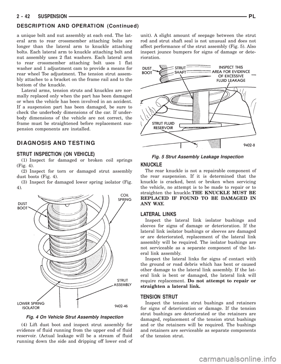
(1) Inspect for damaged or broken coil springs
(Fig. 4).
(2) Inspect for torn or damaged strut assembly
dust boots (Fig. 4).
(3) Inspect for damaged lower spring isolator (Fig.
4).
(4) Lift dust boot and inspect strut assembly for
evidence of fluid running from the upper end of fluid
reservoir. (Actual leakage will be a stream of fluid
running down the side and dripping off lower end ofunit). A slight amount of seepage between the strut
rod and strut shaft seal is not unusual and does not
affect performance of the strut assembly (Fig. 5). Also
inspect jounce bumpers for signs of damage or dete-
rioration.
KNUCKLE
The rear knuckle is not a repairable component of
the rear suspension. If it is determined that the
knuckle is cracked, bent or broken when servicing
the vehicle, no attempt is to be made to repair or to
straighten the knuckle.THE KNUCKLE MUST BE
REPLACED IF FOUND TO BE DAMAGED IN
ANY WAY.
LATERAL LINKS
Inspect the lateral link isolator bushings and
sleeves for signs of damage or deterioration. If the
lateral link isolator bushings or sleeves are damaged
or are deteriorated, replacement of the lateral link
assembly will be required. The isolator bushings are
not serviceable as a separate component of the lat-
eral link assembly.
Inspect the lateral links for signs of contact with
the ground or road debris which has bent or caused
other damage to the lateral link assembly. If the lat-
eral link is bent or damaged, the lateral link will
require replacement.Do not attempt to repair or
straighten a lateral link.
TENSION STRUT
Inspect the tension strut bushings and retainers
for signs of deterioration or damage. If the tension
strut bushings are deteriorated or the retainers are
damaged, replacement of the tension strut bushings
and or the retainers will be required. The bushings
and retainers are serviceable as separate components
of the tension strut.
Fig. 4 On Vehicle Strut Assembly Inspection
Fig. 5 Strut Assembly Leakage Inspection
2 - 42 SUSPENSIONPL
DESCRIPTION AND OPERATION (Continued)
Page 66 of 1200
DIFFERENTIAL AND DRIVELINE
CONTENTS
page page
GENERAL INFORMATION
FRONT DRIVESHAFTS.................... 1
DIAGNOSIS AND TESTING
DRIVESHAFT DIAGNOSIS.................. 2
REMOVAL AND INSTALLATION
FRONT DRIVESHAFTS.................... 2
DISASSEMBLY AND ASSEMBLY
DRIVESHAFT RECONDITION............... 7INNER TRIPOD JOINT SEAL BOOT.......... 9
OUTER C/V JOINT SEAL BOOT............ 13
SPECIFICATIONS
TORQUE.............................. 16
SPECIAL TOOLS
DRIVESHAFT........................... 16
GENERAL INFORMATION
FRONT DRIVESHAFTS
Vehicles equipped with either an automatic or
manual transmission use the unequal±length drive-
shaft system.
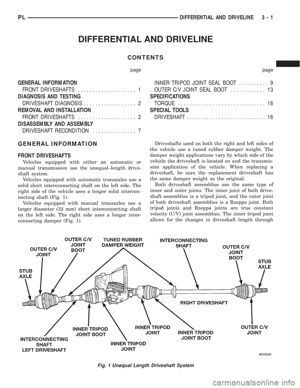
Vehicles equipped with automatic transaxles use a
solid short interconnecting shaft on the left side. The
right side of the vehicle uses a longer solid intercon-
necting shaft (Fig. 1).
Vehicles equipped with manual transaxles use a
larger diameter (32 mm) short interconnecting shaft
on the left side. The right side uses a longer inter-
connecting damper (Fig. 1).Driveshafts used on both the right and left sides of
the vehicle use a tuned rubber damper weight. The
damper weight applications vary by which side of the
vehicle the driveshaft is located on and the transmis-
sion application of the vehicle. When replacing a
driveshaft, be sure the replacement driveshaft has
the same damper weight as the original.
Both driveshaft assemblies use the same type of
inner and outer joints. The inner joint of both drive-
shaft assemblies is a tripod joint, and the outer joint
of both driveshaft assemblies is a Rzeppa joint. Both
tripod joints and Rzeppa joints are true constant
velocity (C/V) joint assemblies. The inner tripod joint
allows for the changes in driveshaft length through
Fig. 1 Unequal Length Driveshaft System
PLDIFFERENTIAL AND DRIVELINE 3 - 1
Page 67 of 1200
the jounce and rebound travel of the front suspen-
sion.
On vehicles equipped with ABS brakes, the outer
C/V joint is equipped with a tone wheel used to
determine vehicle speed for ABS brake operation.
The inner tripod joint of both driveshafts is splined
into the transaxle side gears. The inner tripod joints
are retained in the side gears of the transaxle using
a snap ring located in the stub shaft of the tripod
joint. The outer C/V joint has a stub shaft that is
splined into the wheel hub and retained by a hub nut
using a nut lock and cotter pin.
NOTE: This vehicle does not use a rubber±lip bear-
ing seal as on previous front±wheel±drive cars to
prevent contamination of the front wheel bearing.
On these vehicles, the face of the outer C/V joint
fits deeply into the steering knuckle, using a close
outer C/V joint±to±steering knuckle fit. This design
deters direct water splash on bearing seal while
allowing any water that gets in, to run out the bot-
tom of the steering knuckle bearing bore. It is
important to thoroughly clean the outer C/V joint
and the wheel bearing area in the steering knuckle
before it is assembled after servicing.
DIAGNOSIS AND TESTING
DRIVESHAFT DIAGNOSIS
VEHICLE INSPECTION
(1) Check for grease in the vicinity of the inboard
tripod joint and outboard C/V joint; this is a sign of
inner or outer joint seal boot or seal boot clamp dam-
age.
(2) A light film of grease may appear on the right
inner tripod joint seal boot; this is considered normal
and should not require replacement of the seal boot.
The right inner tripod joint seal boot is made of sili-
cone rubber; which will allow the weeping (sweating)
of the joint lubricant to pass through it while in oper-
ation.
NOISE AND/OR VIBRATION IN TURNS
A clicking noise and/or a vibration in turns could
be caused by one of the following conditions.
(1) Damaged outer C/V or inner tripod joint seal
boot or seal boot clamps. This will result in the loss
and/or contamination of the joint grease, resulting in
inadequate lubrication of the joint.
(2) Noise may also be caused by another compo-
nent of the vehicle coming in contact with the drive-
shafts.
CLUNKING NOISE DURING ACCELERATION
This noise may be a result of one of the following
conditions:
(1) A torn seal boot on the inner or outer joint of
the driveshaft assembly.
(2) A loose or missing clamp on the inner or outer
joint of the driveshaft assembly.
(3) A damaged or worn driveshaft C/V joint.
SHUDDER OR VIBRATION DURING
ACCELERATION
(1) A worn or damaged driveshaft inner tripod
joint.
(2) A sticking tripod joint spider assembly (inner
tripod joint only).
(3) Improper wheel alignment. See Wheel Align-
ment in this group for alignment checking and set-
ting procedures and specifications.
VIBRATION AT HIGHWAY SPEEDS
(1) Foreign material (mud, etc.) packed on the
backside of the wheel(s).
(2) Out of balance front tires or wheels. See Group
22, Wheels And Tires for the required balancing pro-
cedure.
(3) Improper tire and/or wheel runout. See Group
22, Wheels And Tires for the required runout check-
ing procedure.
REMOVAL AND INSTALLATION
FRONT DRIVESHAFTS
CAUTION: Boot sealing is vital to retain special
lubricants and to prevent foreign contaminants
from entering the C/V joint. Mishandling, such as
allowing the assemblies to dangle unsupported, or
pulling or pushing the ends can cut boots or dam-
age C/V joints. During removal and installation pro-
cedures, always support both ends of the driveshaft
to prevent damage.
REMOVAL
CAUTION: The driveshaft, when installed, acts as a
bolt and secures the front hub/bearing assembly. If
vehicle is to be supported or moved on its wheels
with a driveshaft removed, install a PROPER±SIZED
BOLT AND NUT through front hub. Tighten bolt and
nut to 203 N´m (150 ft. lbs.). This will ensure that
the hub bearing cannot loosen.
(1) Remove cotter pin, nut lock, and spring washer
(Fig. 2) from the end of the outer C/V joint stub axle.
(2) Loosen (but do not remove) stub axle±to±hub/
bearing retaining nut (Fig. 3). Loosen hub nut while
3 - 2 DIFFERENTIAL AND DRIVELINEPL
GENERAL INFORMATION (Continued)
Page 72 of 1200
rect fluid level checking procedure for the type of
transaxle being checked.
(17) Lower vehicle.
DISASSEMBLY AND ASSEMBLY
DRIVESHAFT RECONDITION
NOTE: The only service that is to be performed on
the driveshaft assemblies is the replacement of the
driveshaft seal boots.
If any failure of internal driveshaft components is
diagnosed during a vehicle road test or disassembly
of the driveshaft, the driveshaft will need to be
replaced as an assembly.
NOTE: Lubricant requirements and quantities are
different for inner joints than for outer joints. Use
only the recommended lubricants in the required
quantities when servicing driveshaft assemblies.
See (Fig. 21) for the exploded view of the front
driveshaft components.
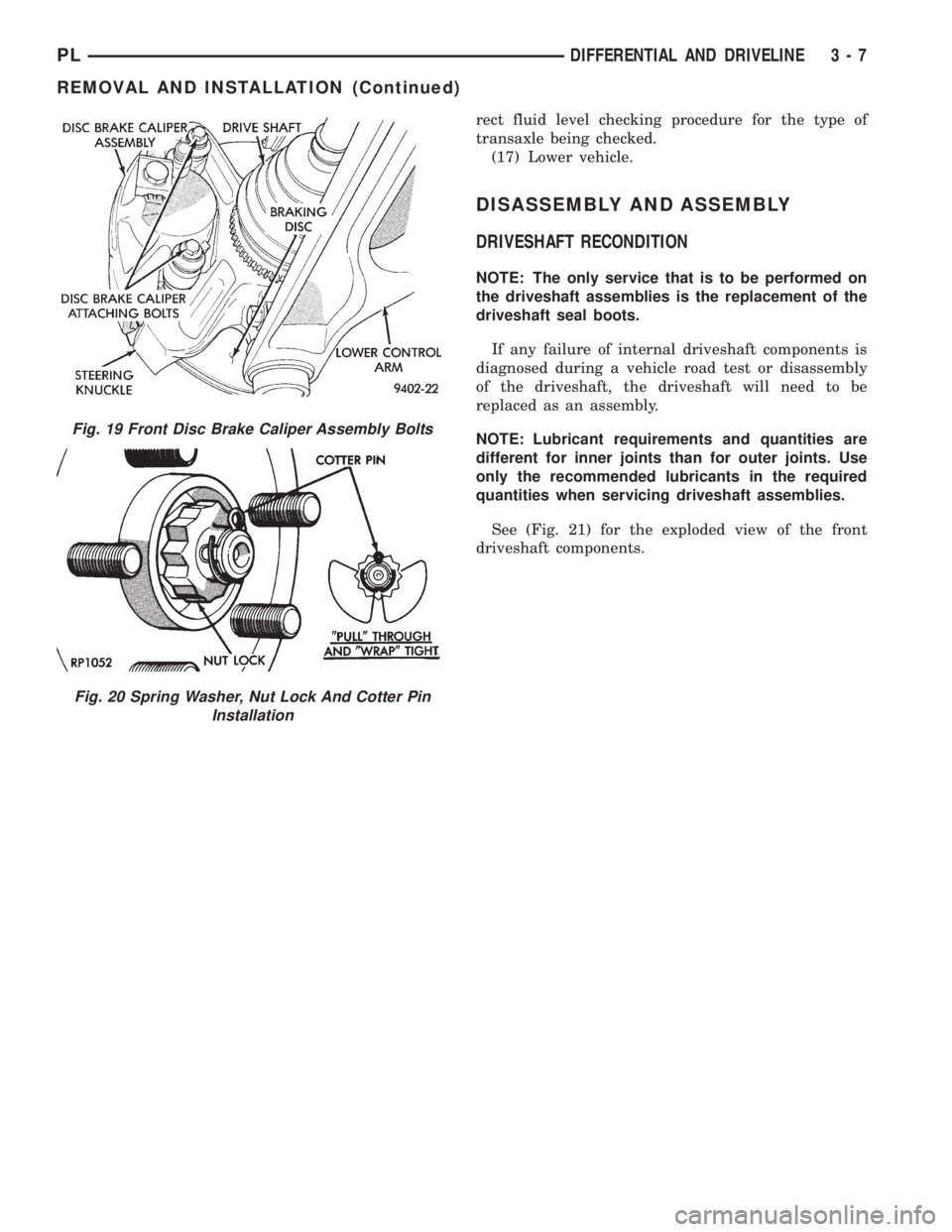
Fig. 19 Front Disc Brake Caliper Assembly Bolts
Fig. 20 Spring Washer, Nut Lock And Cotter Pin
Installation
PLDIFFERENTIAL AND DRIVELINE 3 - 7
REMOVAL AND INSTALLATION (Continued)