1999 DODGE NEON buttons
[x] Cancel search: buttonsPage 298 of 1200

VEHICLE SPEED CONTROL SYSTEM
CONTENTS
page page
GENERAL INFORMATION
INTRODUCTION......................... 1
DESCRIPTION AND OPERATION
POWERTRAIN CONTROL MODULE.......... 3
SERVO CABLE.......................... 3
SPEED CONTROL SERVO.................. 1
SPEED CONTROL SWITCHES.............. 2
STOP LAMP SWITCH..................... 3
VACUUM RESERVOIR.................... 3
VEHICLE SPEED AND DISTANCE............ 3
DIAGNOSIS AND TESTING
CHECKING FOR DIAGNOSTIC CODES........ 4
ELECTRICAL TESTS AT POWERTRAIN
CONTROL MODULE..................... 7
OVERSHOOT/UNDERSHOOT FOLLOWING
SPEED CONTROL SET................... 6ROAD TEST............................ 3
SERVO VACUUM TEST.................... 6
SPEED CONTROL ELECTRICAL TEST........ 4
SPEED CONTROL SWITCH TEST............ 6
STOP LAMP SWITCH TEST................ 6
VACUUM SUPPLY TEST................... 8
VEHICLE SPEED SENSOR................. 8
REMOVAL AND INSTALLATION
POWERTRAIN CONTROL MODULE......... 10
SPEED CONTROL SERVO CABLE............ 9
SPEED CONTROL SERVO.................. 8
SPEED CONTROL SWITCH................. 8
STOP LAMP SWITCH.................... 8
VACUUM RESERVOIR................... 10
VEHICLE SPEED SENSOR................ 10
GENERAL INFORMATION
INTRODUCTION
The speed control system is electronically con-
trolled and vacuum operated. The electronic control
is integrated into the powertrain control module
which is located in the engine compartment. The con-
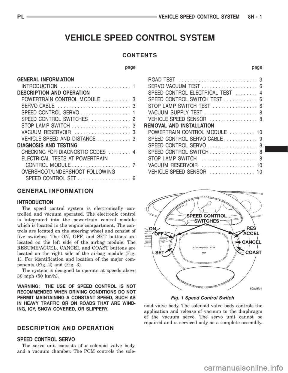
trols are located on the steering wheel and consist of
five switches. The ON, OFF, and SET buttons are
located on the left side of the airbag module. The
RESUME/ACCEL, CANCEL and COAST buttons are
located on the right side of the airbag module (Fig.
1). For identification and location of the major com-
ponents (Fig. 2) and (Fig. 3).
The system is designed to operate at speeds above
30 mph (50 km/h).
WARNING: THE USE OF SPEED CONTROL IS NOT
RECOMMENDED WHEN DRIVING CONDITIONS DO NOT
PERMIT MAINTAINING A CONSTANT SPEED, SUCH AS
IN HEAVY TRAFFIC OR ON ROADS THAT ARE WIND-
ING, ICY, SNOW COVERED, OR SLIPPERY.
DESCRIPTION AND OPERATION
SPEED CONTROL SERVO
The servo unit consists of a solenoid valve body,
and a vacuum chamber. The PCM controls the sole-noid valve body. The solenoid valve body controls the
application and release of vacuum to the diaphragm
of the vacuum servo. The servo unit cannot be
repaired and is serviced only as a complete assembly.
Fig. 1 Speed Control Switch
PLVEHICLE SPEED CONTROL SYSTEM 8H - 1
Page 372 of 1200

REMOTE KEYLESS ENTRY
INDEX
page page
GENERAL INFORMATION
INTRODUCTION......................... 3
DESCRIPTION AND OPERATION
VEHICLE ACCESS CODE (VAC)
PROGRAMMING........................ 3
DIAGNOSIS AND TESTING
REMOTE KEYLESS ENTRY CONDITION....... 4
REMOTE KEYLESS ENTRY SYSTEM......... 5
SERVICE PROCEDURES
HORN CHIRP CANCELLATION.............. 5PANIC FUNCTION CANCELLATION........... 5
PROGRAM REMOTE KEYLESS ENTRY
MODULE.............................. 5
REMOVAL AND INSTALLATION
REMOTE KEYLESS ENTRY MODULE......... 6
SPECIFICATIONS
RKE TRANSMITTER BATTERY.............. 6
RKE TRANSMITTER RANGE................ 6
GENERAL INFORMATION
INTRODUCTION
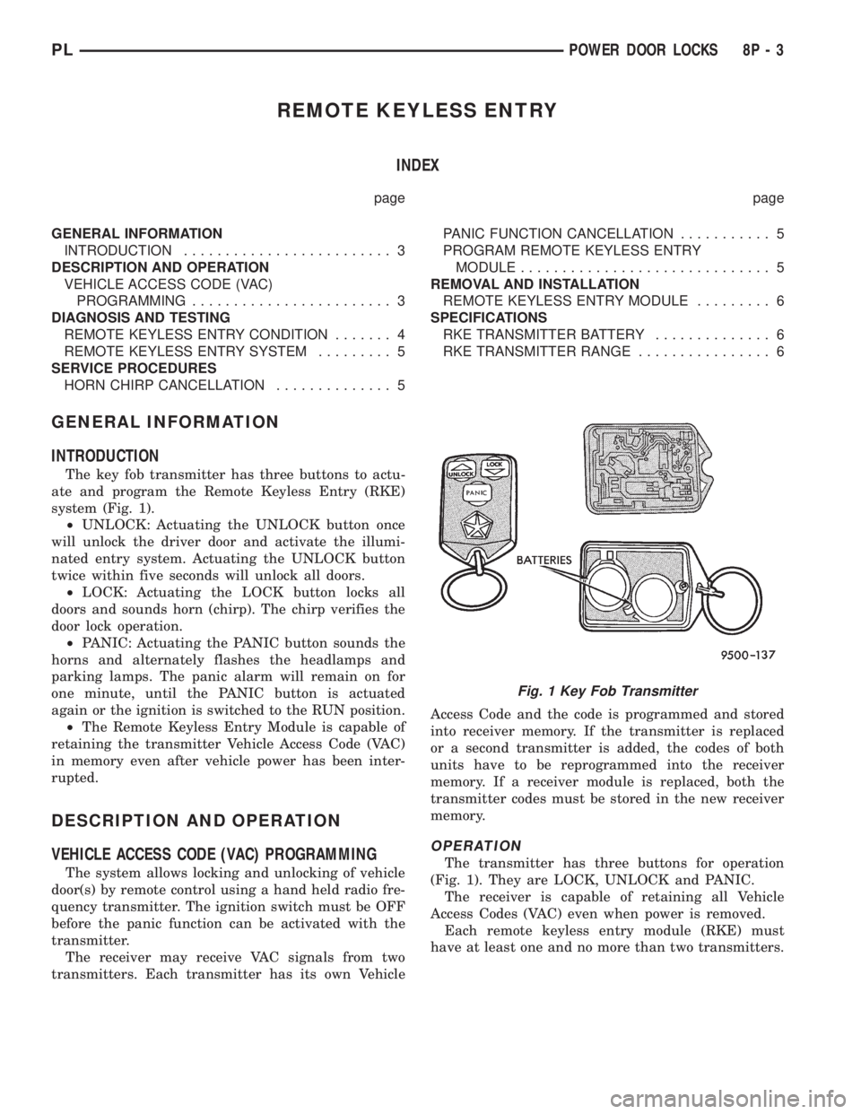
The key fob transmitter has three buttons to actu-
ate and program the Remote Keyless Entry (RKE)
system (Fig. 1).
²UNLOCK: Actuating the UNLOCK button once
will unlock the driver door and activate the illumi-
nated entry system. Actuating the UNLOCK button
twice within five seconds will unlock all doors.
²LOCK: Actuating the LOCK button locks all
doors and sounds horn (chirp). The chirp verifies the
door lock operation.
²PANIC: Actuating the PANIC button sounds the
horns and alternately flashes the headlamps and
parking lamps. The panic alarm will remain on for
one minute, until the PANIC button is actuated
again or the ignition is switched to the RUN position.
²The Remote Keyless Entry Module is capable of
retaining the transmitter Vehicle Access Code (VAC)
in memory even after vehicle power has been inter-
rupted.
DESCRIPTION AND OPERATION
VEHICLE ACCESS CODE (VAC) PROGRAMMING
The system allows locking and unlocking of vehicle
door(s) by remote control using a hand held radio fre-
quency transmitter. The ignition switch must be OFF
before the panic function can be activated with the
transmitter.
The receiver may receive VAC signals from two
transmitters. Each transmitter has its own VehicleAccess Code and the code is programmed and stored
into receiver memory. If the transmitter is replaced
or a second transmitter is added, the codes of both
units have to be reprogrammed into the receiver
memory. If a receiver module is replaced, both the
transmitter codes must be stored in the new receiver
memory.
OPERATION
The transmitter has three buttons for operation
(Fig. 1). They are LOCK, UNLOCK and PANIC.
The receiver is capable of retaining all Vehicle
Access Codes (VAC) even when power is removed.
Each remote keyless entry module (RKE) must
have at least one and no more than two transmitters.
Fig. 1 Key Fob Transmitter
PLPOWER DOOR LOCKS 8P - 3
Page 377 of 1200

transmitter vehicle access codes into the memory of
the immobilizer receiver. Refer to the Vehicle Theft
Security System menu item on the DRB scan tool for
the procedures.
The immobilizer receiver recognizes the Lock and
Unlock signals received from the programmed immo-
bilizer transmitters. If the code sent by the key fob
transmitter is recognized as valid by the Immobilizer
module, it will decode the Crankshaft Position Sensor
signal, enable the starter circuit, and allow the
engine to run.
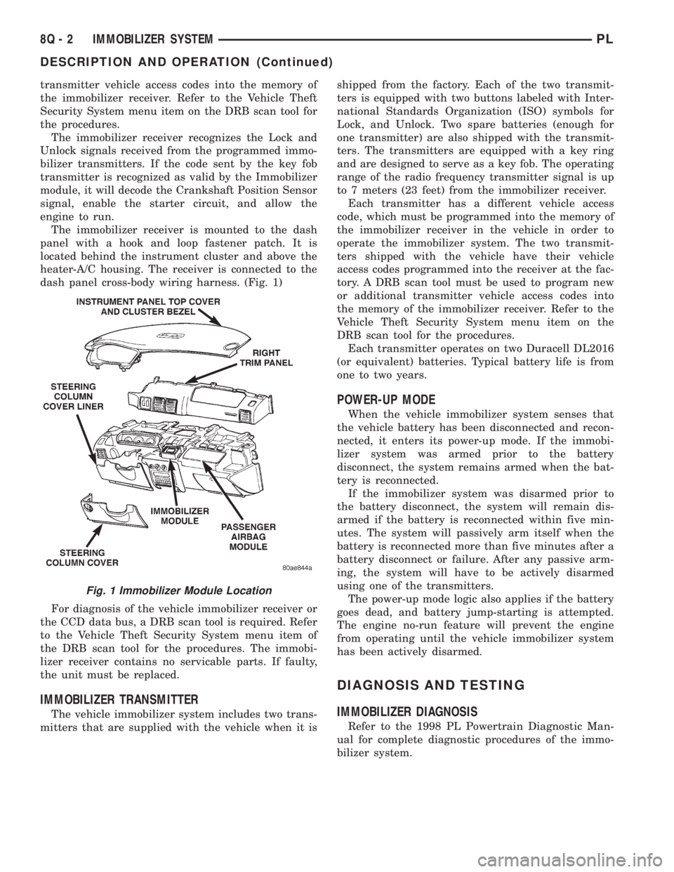
The immobilizer receiver is mounted to the dash
panel with a hook and loop fastener patch. It is
located behind the instrument cluster and above the
heater-A/C housing. The receiver is connected to the
dash panel cross-body wiring harness. (Fig. 1)
For diagnosis of the vehicle immobilizer receiver or
the CCD data bus, a DRB scan tool is required. Refer
to the Vehicle Theft Security System menu item of
the DRB scan tool for the procedures. The immobi-
lizer receiver contains no servicable parts. If faulty,
the unit must be replaced.
IMMOBILIZER TRANSMITTER
The vehicle immobilizer system includes two trans-
mitters that are supplied with the vehicle when it isshipped from the factory. Each of the two transmit-
ters is equipped with two buttons labeled with Inter-
national Standards Organization (ISO) symbols for
Lock, and Unlock. Two spare batteries (enough for
one transmitter) are also shipped with the transmit-
ters. The transmitters are equipped with a key ring
and are designed to serve as a key fob. The operating
range of the radio frequency transmitter signal is up
to 7 meters (23 feet) from the immobilizer receiver.
Each transmitter has a different vehicle access
code, which must be programmed into the memory of
the immobilizer receiver in the vehicle in order to
operate the immobilizer system. The two transmit-
ters shipped with the vehicle have their vehicle
access codes programmed into the receiver at the fac-
tory. A DRB scan tool must be used to program new
or additional transmitter vehicle access codes into
the memory of the immobilizer receiver. Refer to the
Vehicle Theft Security System menu item on the
DRB scan tool for the procedures.
Each transmitter operates on two Duracell DL2016
(or equivalent) batteries. Typical battery life is from
one to two years.
POWER-UP MODE
When the vehicle immobilizer system senses that
the vehicle battery has been disconnected and recon-
nected, it enters its power-up mode. If the immobi-
lizer system was armed prior to the battery
disconnect, the system remains armed when the bat-
tery is reconnected.
If the immobilizer system was disarmed prior to
the battery disconnect, the system will remain dis-
armed if the battery is reconnected within five min-
utes. The system will passively arm itself when the
battery is reconnected more than five minutes after a
battery disconnect or failure. After any passive arm-
ing, the system will have to be actively disarmed
using one of the transmitters.
The power-up mode logic also applies if the battery
goes dead, and battery jump-starting is attempted.
The engine no-run feature will prevent the engine
from operating until the vehicle immobilizer system
has been actively disarmed.
DIAGNOSIS AND TESTING
IMMOBILIZER DIAGNOSIS
Refer to the 1998 PL Powertrain Diagnostic Man-
ual for complete diagnostic procedures of the immo-
bilizer system.
Fig. 1 Immobilizer Module Location
8Q - 2 IMMOBILIZER SYSTEMPL
DESCRIPTION AND OPERATION (Continued)