1999 DODGE NEON stop start
[x] Cancel search: stop startPage 8 of 1200
JUMP STARTING, TOWING AND HOISTING
INDEX
page page
SERVICE PROCEDURES
HOISTING RECOMMENDATIONS............ 9JUMP STARTING PROCEDURE.............. 7
TOWING RECOMMENDATIONS.............. 8
SERVICE PROCEDURES
JUMP STARTING PROCEDURE
WARNING: REVIEW ALL SAFETY PRECAUTIONS
AND WARNINGS IN GROUP 8A, BATTERY/START-
ING/CHARGING SYSTEMS DIAGNOSTICS. DO NOT
JUMP START A FROZEN BATTERY, PERSONAL
INJURY CAN RESULT. DO NOT JUMP START WHEN
MAINTENANCE FREE BATTERY INDICATOR DOT IS
YELLOW OR BRIGHT COLOR. DO NOT JUMP
START A VEHICLE WHEN THE BATTERY FLUID IS
BELOW THE TOP OF LEAD PLATES. DO NOT
ALLOW JUMPER CABLE CLAMPS TO TOUCH
EACH OTHER WHEN CONNECTED TO A BOOSTER
SOURCE. DO NOT USE OPEN FLAME NEAR BAT-
TERY. REMOVE METALLIC JEWELRY WORN ON
HANDS OR WRISTS TO AVOID INJURY BY ACCI-
DENTAL ARCING OF BATTERY CURRENT. WHEN
USING A HIGH OUTPUT BOOSTING DEVICE, DO
NOT ALLOW BATTERY VOLTAGE TO EXCEED 16
VOLTS. REFER TO INSTRUCTIONS PROVIDED
WITH DEVICE BEING USED.
CAUTION: When using another vehicle as a
booster, do not allow vehicles to touch. Electrical
systems can be damaged on either vehicle.
TO JUMP START A DISABLED VEHICLE:
(1) Raise hood on disabled vehicle and visually
inspect engine compartment for:
²Battery cable clamp condition, clean if necessary.
²Frozen battery.
²Yellow or bright color test indicator, if equipped.
²Low battery fluid level.
²Generator drive belt condition and tension.
²Fuel fumes or leakage, correct if necessary.
CAUTION: If the cause of starting problem on dis-
abled vehicle is severe, damage to booster vehicle
charging system can result.
(2) When using another vehicle as a booster
source, park the booster vehicle within cable reach.
Turn off all accessories, set the parking brake, placethe automatic transmission in PARK or the manual
transmission in NEUTRAL and turn the ignition
OFF.
(3) On disabled vehicle, place gear selector in park
or neutral and set park brake. Turn off all accesso-
ries.
(4) Connect jumper cables to booster battery. RED
clamp to positive terminal (+). BLACK clamp to neg-
ative terminal (-). DO NOT allow clamps at opposite
end of cables to touch, electrical arc will result.
Review all warnings in this procedure.
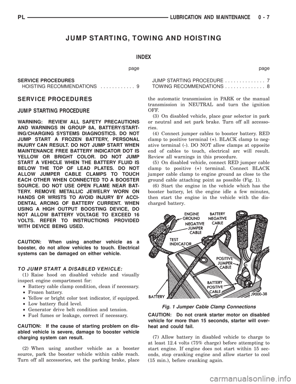
(5) On disabled vehicle, connect RED jumper cable
clamp to positive (+) terminal. Connect BLACK
jumper cable clamp to engine ground as close to the
ground cable attaching point as possible (Fig. 1).
(6) Start the engine in the vehicle which has the
booster battery, let the engine idle a few minutes,
then start the engine in the vehicle with the dis-
charged battery.
CAUTION: Do not crank starter motor on disabled
vehicle for more than 15 seconds, starter will over-
heat and could fail.
(7) Allow battery in disabled vehicle to charge to
at least 12.4 volts (75% charge) before attempting to
start engine. If engine does not start within 15 sec-
onds, stop cranking engine and allow starter to cool
(15 min.), before cranking again.
Fig. 1 Jumper Cable Clamp Connections
PLLUBRICATION AND MAINTENANCE 0 - 7
Page 113 of 1200
(4) Carefully lower caliper and brake shoe assem-
blies over braking disc (rotor) reversing the required
removal procedure (Fig. 71). Make sure that the cal-
iper guide pin bolts, bushings and sleeves are clear of
the adapter bosses.
CAUTION: Extreme caution should be taken not to
cross thread the caliper guide pin bolts when they
are installed.
(5) Install caliper assembly guide pin bolts into
adapter and tighten (Fig. 70). Then torque both guide
pin bolts to 22 N´m (192 in. lbs.).
(6) Install the wheel and tire assembly.
(7) Tighten the wheel mounting stud nuts in
proper sequence until all nuts are torqued to half
specification. Then repeat the tightening sequence to
the full specified torque of 135 N´m (100 ft. lbs.).
(8) Remove jackstands or lower hoist.Before
moving vehicle, pump the brake pedal several
times to insure the vehicle has a firm brake
pedal.
(9) Road test the vehicle and make several stops to
wear off any foreign material on the brakes and to
seat the brake pads.
REAR DISC BRAKE SHOES
WARNING: ALTHOUGH FACTORY INSTALLED
BRAKELININGS ARE MADE FROM ASBESTOS
FREE MATERIALS, SOME AFTER MARKET BRAKE-
LINING MAY CONTAIN ASBESTOS. THIS SHOULD
BE TAKEN INTO ACCOUNT WHEN SERVICING A
VEHICLE'S BRAKE SYSTEM, WHEN AFTERMARKET
BRAKELININGS MAY HAVE BEEN INSTALLED ON
THE VEHICLE. ALWAYS WEAR A RESPIRATOR
WHEN CLEANING BRAKE COMPONENTS AS
ASBESTOS CAN CAUSE SERIOUS BODILY HARM
SUCH AS ASBESTOSIS AND OR CANCER. NEVER
CLEAN BRAKE COMPONENTS BY USING COM-
PRESSED AIR, USE ONLY A VACUUM CLEANER
SPECIFICALLY DESIGNED FOR THE REMOVAL OF
BRAKE DUST. IF A VACUUM CLEANER IS NOT
AVAILABLE, CLEAN BRAKE PARTS USING ONLY
WATER DAMPENED SHOP TOWELS. DO NOT CRE-
ATE BRAKELINING DUST BY SANDING BRAKE LIN-
INGS WHEN SERVICING A VEHICLE. DISPOSE OF
ALL DUST AND DIRT SUSPECTED OF CONTAINING
ASBESTOS FIBERS USING ONLY SEALED AIR-
TIGHT BAGS OR CONTAINERS. FOLLOW ALL REC-
OMMENDED SAFETY PRACTICES PRESCRIBED BY
THE OCCUPATIONAL SAFETY AND HEALTH ADMIN-
ISTRATION (OSHA) AND THE ENVIRONMENTAL
PROTECTION AGENCY (EPA), FOR HANDLING AND
DISPOSAL OF PRODUCTS CONTAINING ASBES-
TOS.During service procedures, grease or any other for-
eign material must be kept off caliper assembly, sur-
faces of braking rotor and external surfaces of hub.
Handling of the braking rotor and caliper should
be done in such a way as to avoid deformation of the
rotor and scratching or nicking of the brake linings.
If inspection reveals that the square sectioned cal-
iper piston seal is worn or damaged, it should be
replaced immediately.
During removal and installation of a wheel and
tire assembly, use care not to strike the caliper.
NOTE: Before vehicle is moved after any brake
service work, pump the brake pedal several times
to insure the vehicle has a firm brake pedal.
NOTE: Starting with the 1998 model year, different
lining material is used on the rear disc brake shoes.
Vehicles equipped with optional 4 wheel disc
brakes use a new lining material on the rear disc
brake shoes than prior model year vehicles
equipped with this brake system. When new brake
shoes are installed, be sure brake shoes for the
correct model year and type of brake system the
vehicle is equipped with are used.REMOVE
(1) Raise vehicle on jackstands or centered on a
hoist. See Hoisting in the Lubrication and Mainte-
nance section of this manual.
(2) Remove rear wheel and tire assemblies from
vehicle.
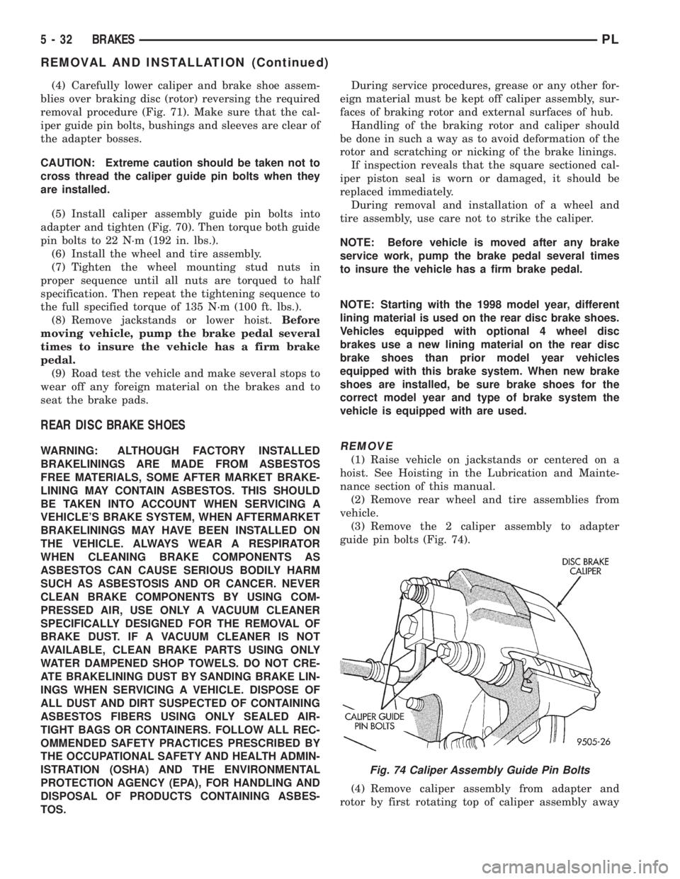
(3) Remove the 2 caliper assembly to adapter
guide pin bolts (Fig. 74).
(4) Remove caliper assembly from adapter and
rotor by first rotating top of caliper assembly away
Fig. 74 Caliper Assembly Guide Pin Bolts
5 - 32 BRAKESPL
REMOVAL AND INSTALLATION (Continued)
Page 151 of 1200
This is accomplished by a sophisticated system of
electrical and hydraulic components. As a result,
there are a few performance characteristics that may
at first seem different but should be considered nor-
mal. These characteristics are discussed below.
NORMAL BRAKING SYSTEM FUNCTION
Under normal braking conditions, the ABS System
functions the same as a standard brake system with
a diagonally split master cylinder and conventional
vacuum assist.
ABS SYSTEM OPERATION
If a wheel locking tendency is detected during a
brake application, the brake system will enter the
ABS mode. During ABS braking, hydraulic pressure
in the four wheel circuits is modulated to prevent
any wheel from locking. Each wheel circuit is
designed with a set of electric solenoids to allow mod-
ulation, although for vehicle stability, both rear
wheel solenoids receive the same electrical signal.
During an ABS stop, the brakes hydraulic system
is still diagonally split. However, the brake system
pressure is further split into four control channels.
During antilock operation of the vehicle's brake sys-
tem the front wheels are controlled independently
and are on two separate control channels and the
rear wheels of the vehicle are controlled together.
The system can build and release pressure at each
wheel, depending on signals generated by the wheel
speed sensors (WSS) at each wheel and received at
the Controller Antilock Brake (CAB).
ABS operation is available at all vehicle speeds
above 3 to 5 mph. Wheel lockup may be perceived at
the very end of an ABS stop and is considered nor-
mal.
VEHICLE HANDLING PERFORMANCE DURING
ABS BRAKING
It is important to remember that an antilock brake
system does not shorten a vehicle's stopping distance
under all driving conditions, but does provide
improved control of the vehicle while stopping. Vehi-
cle stopping distance is still dependent on vehicle
speed, weight, tires, road surfaces and other factors.
Though ABS provides the driver with some steer-
ing control during hard braking, there are conditions
however, where the system does not provide any ben-
efit. In particular, hydroplaning is still possible when
the tires ride on a film of water. This results in the
vehicles tires leaving the road surface rendering the
vehicle virtually uncontrollable. In addition, extreme
steering maneuvers at high speed or high speed cor-
nering beyond the limits of tire adhesion to the road
surface may cause vehicle skidding, independent of
vehicle braking. For this reason, the ABS system is
termed Antilock instead of Anti-Skid.
NOISE AND BRAKE PEDAL FEEL
During ABS braking, some brake pedal movement
may be felt. In addition, ABS braking will create
ticking, popping and/or groaning noises heard by the
driver. This is normal due to pressurized fluid being
transferred between the master cylinder and the
brakes. If ABS operation occurs during hard braking,
some pulsation may be felt in the vehicle body due to
fore and aft movement of the suspension as brake
pressures are modulated.
At the end of an ABS stop, ABS will be turned off
when the vehicle is slowed to a speed of 3±4 mph.
There may be a slight brake pedal drop anytime that
the ABS is deactivated, such as at the end of the stop
when the vehicle speed is less then 3 mph or during
an ABS stop where ABS is no longer required. These
conditions will exist when a vehicle is being stopped
on a road surface with patches of ice, loose gravel or
sand on it. Also stopping a vehicle on a bumpy road
surface will activate ABS because of the wheel hop
caused by the bumps.
TIRE NOISE AND MARKS
Although the ABS system prevents complete wheel
lock-up, some wheel slip is desired in order to
achieve optimum braking performance. Wheel slip is
defined as follows, 0 percent slip means the wheel is
rolling freely and 100 percent slip means the wheel is
fully locked. During brake pressure modulation,
wheel slip is allowed to reach up to 25 to30%. This
means that the wheel rolling velocity is 25 to 30%
less than that of a free rolling wheel at a given vehi-
cle speed. This slip may result in some tire chirping,
depending on the road surface. This sound should not
be interpreted as total wheel lock-up.
Complete wheel lock up normally leaves black tire
marks on dry pavement. The ABS System will not
leave dark black tire marks since the wheel never
reaches a fully locked condition. Tire marks may
however be noticeable as light patched marks.
START UP CYCLE
When the ignition is turned on, a popping sound
and a slight brake pedal movement may be noticed.
Additionally, when the vehicle is first driven off a
humming may be heard and/or felt by the driver at
approximately 20 to 40 kph (12 to 25 mph). The ABS
warning lamp will also be on for up to 5 seconds
after the ignition is turned on. All of these conditions
are a normal function of ABS as the system is per-
forming a diagnosis check.
5 - 70 BRAKESPL
DESCRIPTION AND OPERATION (Continued)
Page 161 of 1200
malfunction has occurred with one of the proportion-
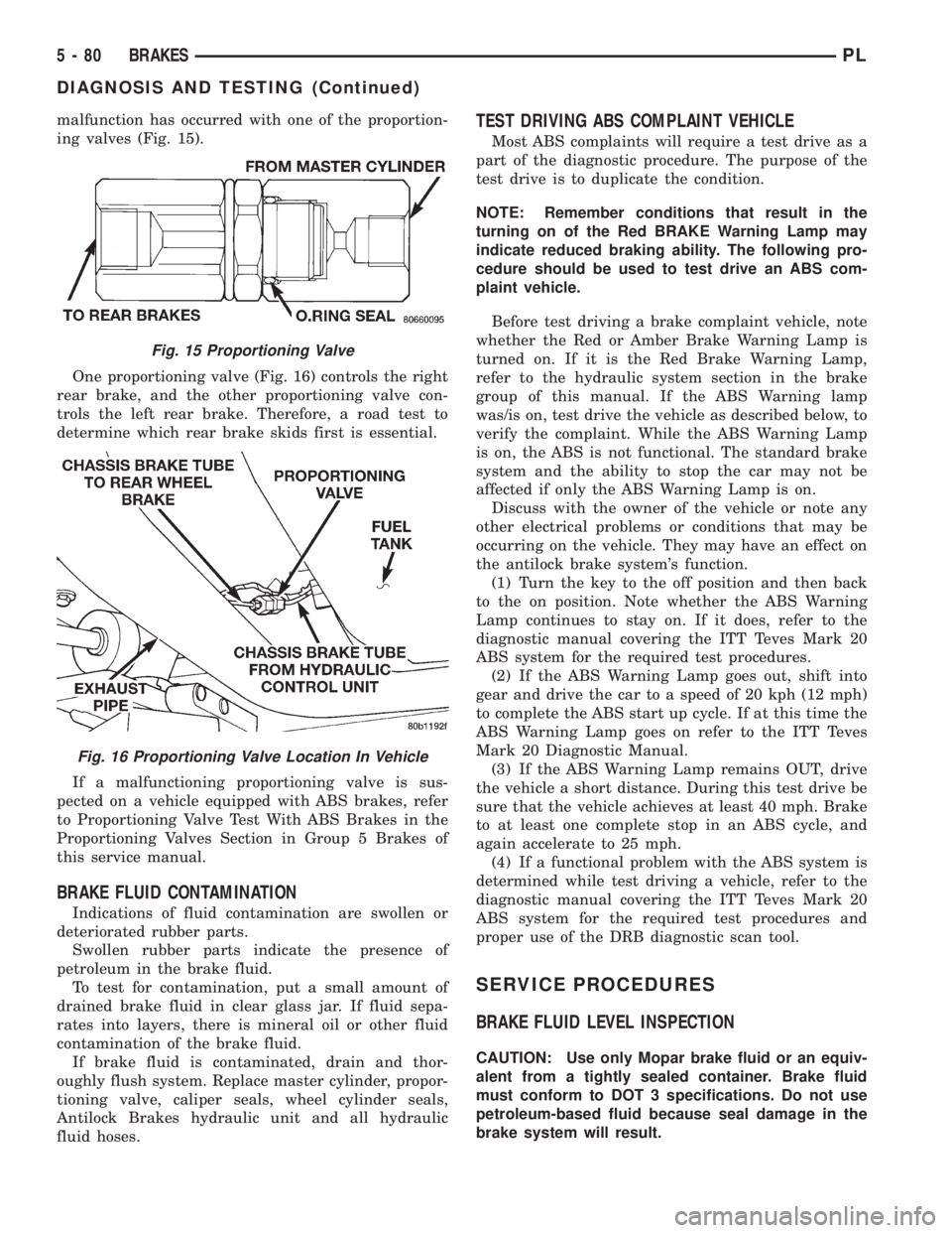
ing valves (Fig. 15).
One proportioning valve (Fig. 16) controls the right
rear brake, and the other proportioning valve con-
trols the left rear brake. Therefore, a road test to
determine which rear brake skids first is essential.
If a malfunctioning proportioning valve is sus-
pected on a vehicle equipped with ABS brakes, refer
to Proportioning Valve Test With ABS Brakes in the
Proportioning Valves Section in Group 5 Brakes of
this service manual.
BRAKE FLUID CONTAMINATION
Indications of fluid contamination are swollen or
deteriorated rubber parts.
Swollen rubber parts indicate the presence of
petroleum in the brake fluid.
To test for contamination, put a small amount of
drained brake fluid in clear glass jar. If fluid sepa-
rates into layers, there is mineral oil or other fluid
contamination of the brake fluid.
If brake fluid is contaminated, drain and thor-
oughly flush system. Replace master cylinder, propor-
tioning valve, caliper seals, wheel cylinder seals,
Antilock Brakes hydraulic unit and all hydraulic
fluid hoses.
TEST DRIVING ABS COMPLAINT VEHICLE
Most ABS complaints will require a test drive as a
part of the diagnostic procedure. The purpose of the
test drive is to duplicate the condition.
NOTE: Remember conditions that result in the
turning on of the Red BRAKE Warning Lamp may
indicate reduced braking ability. The following pro-
cedure should be used to test drive an ABS com-
plaint vehicle.
Before test driving a brake complaint vehicle, note
whether the Red or Amber Brake Warning Lamp is
turned on. If it is the Red Brake Warning Lamp,
refer to the hydraulic system section in the brake
group of this manual. If the ABS Warning lamp
was/is on, test drive the vehicle as described below, to
verify the complaint. While the ABS Warning Lamp
is on, the ABS is not functional. The standard brake
system and the ability to stop the car may not be
affected if only the ABS Warning Lamp is on.
Discuss with the owner of the vehicle or note any
other electrical problems or conditions that may be
occurring on the vehicle. They may have an effect on
the antilock brake system's function.
(1) Turn the key to the off position and then back
to the on position. Note whether the ABS Warning
Lamp continues to stay on. If it does, refer to the
diagnostic manual covering the ITT Teves Mark 20
ABS system for the required test procedures.
(2) If the ABS Warning Lamp goes out, shift into
gear and drive the car to a speed of 20 kph (12 mph)
to complete the ABS start up cycle. If at this time the
ABS Warning Lamp goes on refer to the ITT Teves
Mark 20 Diagnostic Manual.
(3) If the ABS Warning Lamp remains OUT, drive
the vehicle a short distance. During this test drive be
sure that the vehicle achieves at least 40 mph. Brake
to at least one complete stop in an ABS cycle, and
again accelerate to 25 mph.
(4) If a functional problem with the ABS system is
determined while test driving a vehicle, refer to the
diagnostic manual covering the ITT Teves Mark 20
ABS system for the required test procedures and
proper use of the DRB diagnostic scan tool.
SERVICE PROCEDURES
BRAKE FLUID LEVEL INSPECTION
CAUTION: Use only Mopar brake fluid or an equiv-
alent from a tightly sealed container. Brake fluid
must conform to DOT 3 specifications. Do not use
petroleum-based fluid because seal damage in the
brake system will result.
Fig. 15 Proportioning Valve
Fig. 16 Proportioning Valve Location In Vehicle
5 - 80 BRAKESPL
DIAGNOSIS AND TESTING (Continued)
Page 303 of 1200
OVERSHOOT/UNDERSHOOT FOLLOWING SPEED
CONTROL SET
If the operator repeatedly presses and releases the
set button with their foot off of the accelerator (a ªlift
foot setº to begin speed control operation), the vehicle
may accelerate and exceed the desired set speed by
up to 5 MPH (8 km/h) and then decelerate to less
than the desired set speed before finally achieving
the desired set speed.
The Speed Control has an adaptive strategy that
compensates for vehicle-to-vehicle variations in speed
control cable lengths. When the speed control is set
with the vehicle operators foot off of the accelerator
pedal, the speed control thinks there is excessive
speed control cable slack and adapts. If the lift foot
sets are continually used, the speed control over-
shoot/undershoot condition will develop.
To ªunlearnº the overshoot/undershoot condition,
the vehicle operator has to press and release the set
button while maintaining the desired set speed with
the accelerator pedal (not decelerating or accelerat-
ing), and then turn the cruise control switch to the
OFF position (or press the CANCEL button if
equipped) after waiting 10 seconds. This procedure
must be performed approximately 10±15 times to
completely unlearn the overshoot/undershoot condi-
tion.
SERVO VACUUM TEST
(1) Turn ignition switch to the ON position with-
out starting engine. Activate speed control ON
switch.
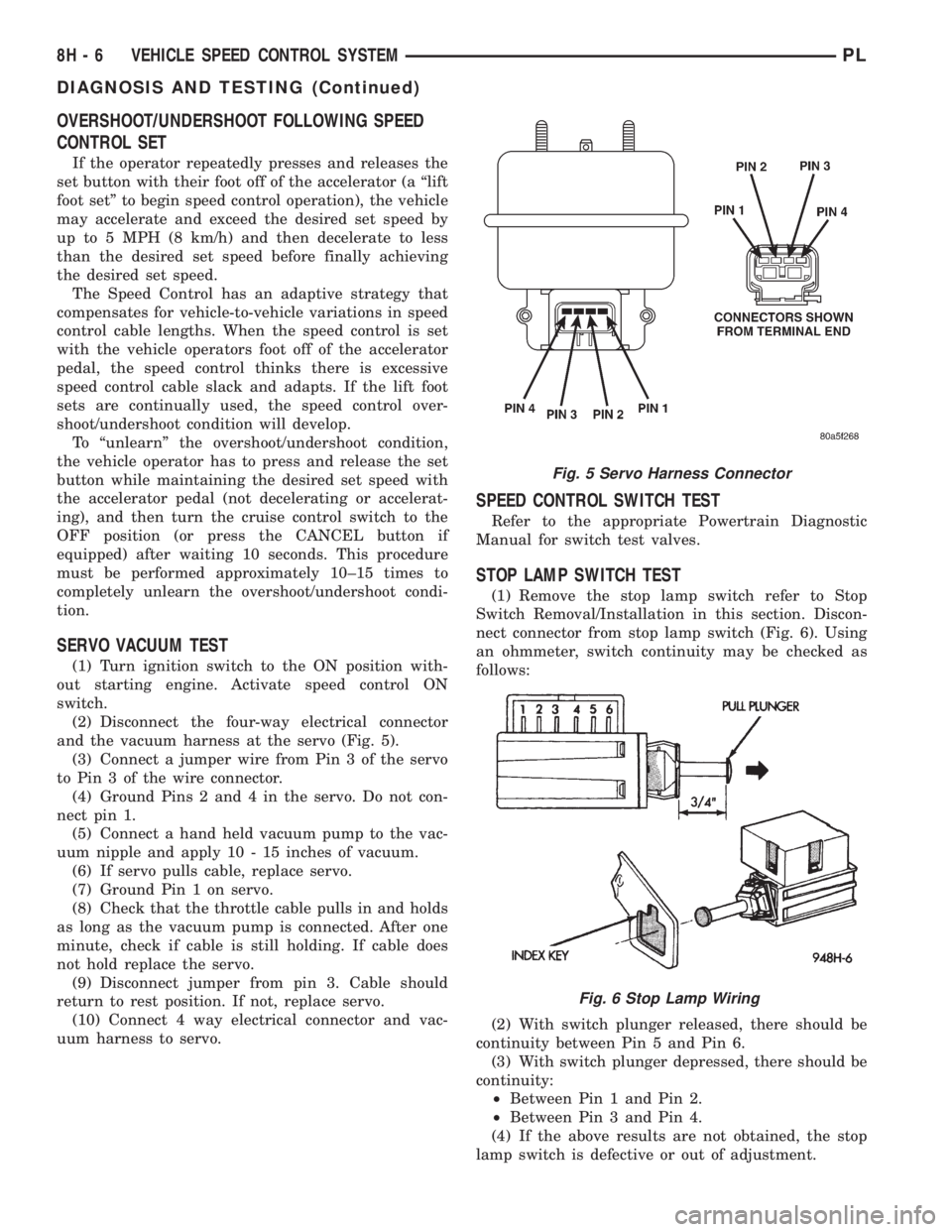
(2) Disconnect the four-way electrical connector
and the vacuum harness at the servo (Fig. 5).
(3) Connect a jumper wire from Pin 3 of the servo
to Pin 3 of the wire connector.
(4) Ground Pins 2 and 4 in the servo. Do not con-
nect pin 1.
(5) Connect a hand held vacuum pump to the vac-
uum nipple and apply 10 - 15 inches of vacuum.
(6) If servo pulls cable, replace servo.
(7) Ground Pin 1 on servo.
(8) Check that the throttle cable pulls in and holds
as long as the vacuum pump is connected. After one
minute, check if cable is still holding. If cable does
not hold replace the servo.
(9) Disconnect jumper from pin 3. Cable should
return to rest position. If not, replace servo.
(10) Connect 4 way electrical connector and vac-
uum harness to servo.
SPEED CONTROL SWITCH TEST
Refer to the appropriate Powertrain Diagnostic
Manual for switch test valves.
STOP LAMP SWITCH TEST
(1) Remove the stop lamp switch refer to Stop
Switch Removal/Installation in this section. Discon-
nect connector from stop lamp switch (Fig. 6). Using
an ohmmeter, switch continuity may be checked as
follows:
(2) With switch plunger released, there should be
continuity between Pin 5 and Pin 6.
(3) With switch plunger depressed, there should be
continuity:
²Between Pin 1 and Pin 2.
²Between Pin 3 and Pin 4.
(4) If the above results are not obtained, the stop
lamp switch is defective or out of adjustment.
Fig. 5 Servo Harness Connector
Fig. 6 Stop Lamp Wiring
8H - 6 VEHICLE SPEED CONTROL SYSTEMPL
DIAGNOSIS AND TESTING (Continued)
Page 305 of 1200
(c) If continuity is OK between cavity 62 and
cavity 1, repair open circuit between cavity 2 of the
stop lamp switch connector and ground.
(6) Using an ohmmeter, check continuity from cav-
ity 76 on PCM connector to ground with the trans-
mission in park or neutral. If no continuity, test TRS/
Park-Neutral switch and switch wiring
(7) Turn speed control and ignition switch OFF.
(8) Unplug the BLACK 40-way connector from the
Powertrain Control Module (PCM)
(9) Using an ohmmeter, check continuity from cav-
ity 3 of servo connector to cavity 5 on the PCM con-
nector.
(a) If continuity is OK, replace PCM. Check cir-
cuit for short to ground before replacing PCM.
(b) If no continuity, remove stop lamp switch
and conduct Stop Lamp Switch Test. If test fails,
adjust or replace as necessary.
(c) If switch passes, measure continuity from
cavity 4 of stop lamp switch connector to cavity 3
of servo connector. Repair open circuit if necessary.
(d) If continuity is OK, measure continuity from
cavity 3 of stop lamp switch to cavity 5 of PCM
connector. Repair open circuit as necessary.
(e) Install PCM connectors onto PCM and speed
control servo connector to servo.
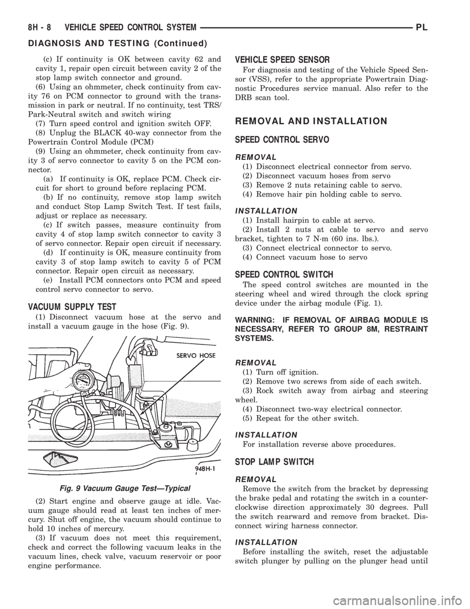
VACUUM SUPPLY TEST
(1) Disconnect vacuum hose at the servo and
install a vacuum gauge in the hose (Fig. 9).
(2) Start engine and observe gauge at idle. Vac-
uum gauge should read at least ten inches of mer-
cury. Shut off engine, the vacuum should continue to
hold 10 inches of mercury.
(3) If vacuum does not meet this requirement,
check and correct the following vacuum leaks in the
vacuum lines, check valve, vacuum reservoir or poor
engine performance.
VEHICLE SPEED SENSOR
For diagnosis and testing of the Vehicle Speed Sen-
sor (VSS), refer to the appropriate Powertrain Diag-
nostic Procedures service manual. Also refer to the
DRB scan tool.
REMOVAL AND INSTALLATION
SPEED CONTROL SERVO
REMOVAL
(1) Disconnect electrical connector from servo.
(2) Disconnect vacuum hoses from servo
(3) Remove 2 nuts retaining cable to servo.
(4) Remove hair pin holding cable to servo.
INSTALLATION
(1) Install hairpin to cable at servo.
(2) Install 2 nuts at cable to servo and servo
bracket, tighten to 7 N´m (60 ins. lbs.).
(3) Connect electrical connector to servo.
(4) Connect vacuum hose to servo
SPEED CONTROL SWITCH
The speed control switches are mounted in the
steering wheel and wired through the clock spring
device under the airbag module (Fig. 1).
WARNING: IF REMOVAL OF AIRBAG MODULE IS
NECESSARY, REFER TO GROUP 8M, RESTRAINT
SYSTEMS.
REMOVAL
(1) Turn off ignition.
(2) Remove two screws from side of each switch.
(3) Rock switch away from airbag and steering
wheel.
(4) Disconnect two-way electrical connector.
(5) Repeat for the other switch.
INSTALLATION
For installation reverse above procedures.
STOP LAMP SWITCH
REMOVAL
Remove the switch from the bracket by depressing
the brake pedal and rotating the switch in a counter-
clockwise direction approximately 30 degrees. Pull
the switch rearward and remove from bracket. Dis-
connect wiring harness connector.
INSTALLATION
Before installing the switch, reset the adjustable
switch plunger by pulling on the plunger head until
Fig. 9 Vacuum Gauge TestÐTypical
8H - 8 VEHICLE SPEED CONTROL SYSTEMPL
DIAGNOSIS AND TESTING (Continued)
Page 316 of 1200
(b) If fuse blows, disconnect wiper switch and
replace fuse.
(c) If fuse does not blow, replace switch.
(d) If fuse blows, repair wiring as necessary.
MOTOR OPERATES SLOWLY AT ALL SPEEDS
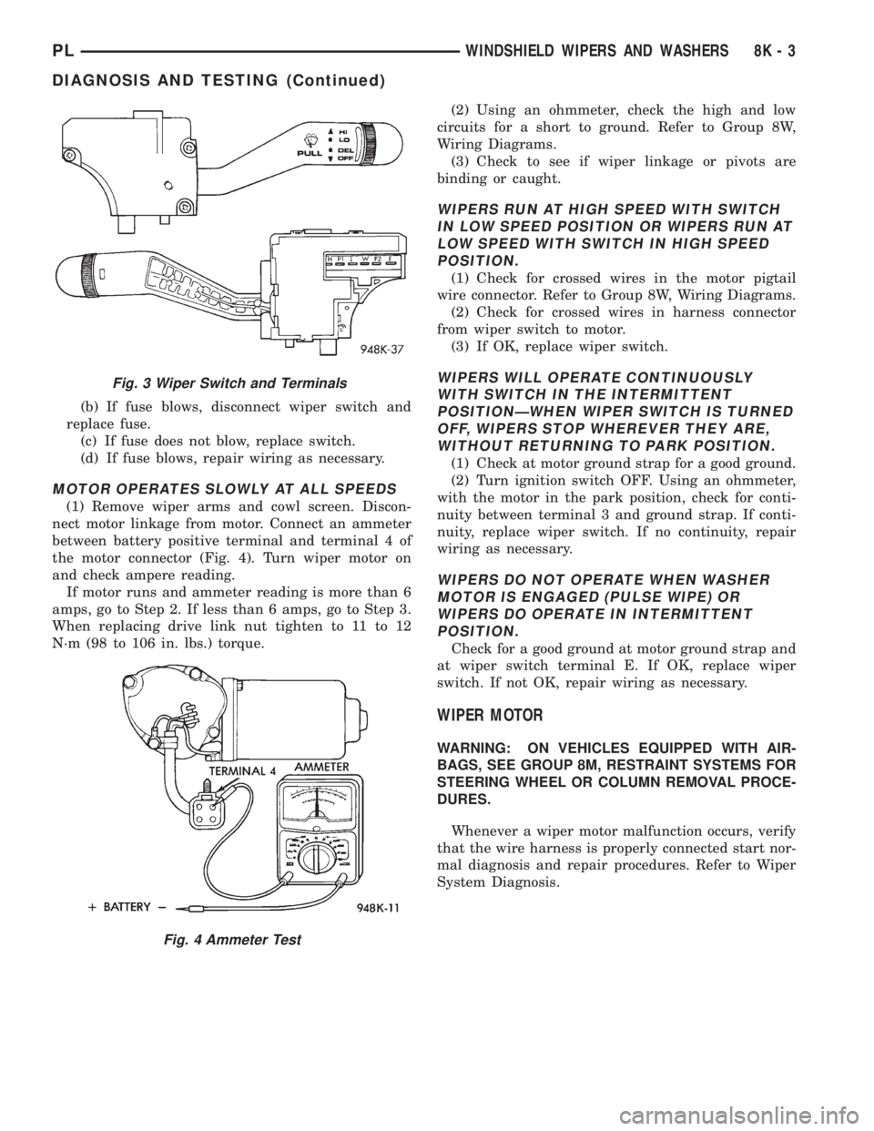
(1) Remove wiper arms and cowl screen. Discon-
nect motor linkage from motor. Connect an ammeter
between battery positive terminal and terminal 4 of
the motor connector (Fig. 4). Turn wiper motor on
and check ampere reading.
If motor runs and ammeter reading is more than 6
amps, go to Step 2. If less than 6 amps, go to Step 3.
When replacing drive link nut tighten to 11 to 12
N´m (98 to 106 in. lbs.) torque.(2) Using an ohmmeter, check the high and low
circuits for a short to ground. Refer to Group 8W,
Wiring Diagrams.
(3) Check to see if wiper linkage or pivots are
binding or caught.
WIPERS RUN AT HIGH SPEED WITH SWITCH
IN LOW SPEED POSITION OR WIPERS RUN AT
LOW SPEED WITH SWITCH IN HIGH SPEED
POSITION.
(1) Check for crossed wires in the motor pigtail
wire connector. Refer to Group 8W, Wiring Diagrams.
(2) Check for crossed wires in harness connector
from wiper switch to motor.
(3) If OK, replace wiper switch.
WIPERS WILL OPERATE CONTINUOUSLY
WITH SWITCH IN THE INTERMITTENT
POSITIONÐWHEN WIPER SWITCH IS TURNED
OFF, WIPERS STOP WHEREVER THEY ARE,
WITHOUT RETURNING TO PARK POSITION.
(1) Check at motor ground strap for a good ground.
(2) Turn ignition switch OFF. Using an ohmmeter,
with the motor in the park position, check for conti-
nuity between terminal 3 and ground strap. If conti-
nuity, replace wiper switch. If no continuity, repair
wiring as necessary.
WIPERS DO NOT OPERATE WHEN WASHER
MOTOR IS ENGAGED (PULSE WIPE) OR
WIPERS DO OPERATE IN INTERMITTENT
POSITION.
Check for a good ground at motor ground strap and
at wiper switch terminal E. If OK, replace wiper
switch. If not OK, repair wiring as necessary.
WIPER MOTOR
WARNING: ON VEHICLES EQUIPPED WITH AIR-
BAGS, SEE GROUP 8M, RESTRAINT SYSTEMS FOR
STEERING WHEEL OR COLUMN REMOVAL PROCE-
DURES.
Whenever a wiper motor malfunction occurs, verify
that the wire harness is properly connected start nor-
mal diagnosis and repair procedures. Refer to Wiper
System Diagnosis.
Fig. 3 Wiper Switch and Terminals
Fig. 4 Ammeter Test
PLWINDSHIELD WIPERS AND WASHERS 8K - 3
DIAGNOSIS AND TESTING (Continued)
Page 321 of 1200
WINDSHIELD WASHER SYSTEM
INDEX
page page
DESCRIPTION AND OPERATION
WASHER NOZZLE........................ 8
DIAGNOSIS AND TESTING
WINDSHIELD WASHERS................... 8REMOVAL AND INSTALLATION
WASHER NOZZLE........................ 9
WASHER RESERVOIR PUMP.............. 10
WASHER RESERVOIR..................... 9
DESCRIPTION AND OPERATION
WASHER NOZZLE
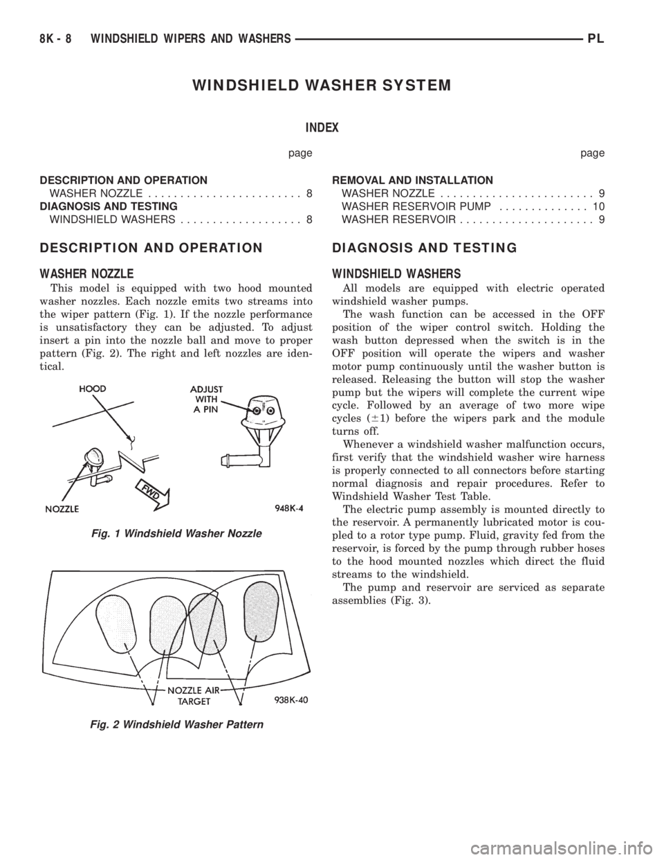
This model is equipped with two hood mounted
washer nozzles. Each nozzle emits two streams into
the wiper pattern (Fig. 1). If the nozzle performance
is unsatisfactory they can be adjusted. To adjust
insert a pin into the nozzle ball and move to proper
pattern (Fig. 2). The right and left nozzles are iden-
tical.
DIAGNOSIS AND TESTING
WINDSHIELD WASHERS
All models are equipped with electric operated
windshield washer pumps.
The wash function can be accessed in the OFF
position of the wiper control switch. Holding the
wash button depressed when the switch is in the
OFF position will operate the wipers and washer
motor pump continuously until the washer button is
released. Releasing the button will stop the washer
pump but the wipers will complete the current wipe
cycle. Followed by an average of two more wipe
cycles (61) before the wipers park and the module
turns off.
Whenever a windshield washer malfunction occurs,
first verify that the windshield washer wire harness
is properly connected to all connectors before starting
normal diagnosis and repair procedures. Refer to
Windshield Washer Test Table.
The electric pump assembly is mounted directly to
the reservoir. A permanently lubricated motor is cou-
pled to a rotor type pump. Fluid, gravity fed from the
reservoir, is forced by the pump through rubber hoses
to the hood mounted nozzles which direct the fluid
streams to the windshield.
The pump and reservoir are serviced as separate
assemblies (Fig. 3).
Fig. 1 Windshield Washer Nozzle
Fig. 2 Windshield Washer Pattern
8K - 8 WINDSHIELD WIPERS AND WASHERSPL