1999 DODGE NEON check oil
[x] Cancel search: check oilPage 4 of 1200
MAINTENANCE SCHEDULES
INDEX
page page
GENERAL INFORMATION
INTRODUCTION......................... 3
SCHEDULE ± A.......................... 3SCHEDULE ± B.......................... 4
UNSCHEDULED INSPECTION............... 3
GENERAL INFORMATION
INTRODUCTION
Service and maintenance procedures for compo-
nents and systems listed in Schedule ± A or B can be
found by using the Group Tab Locator index at the
front of this manual. If it is not clear which group
contains the information needed, refer to the index at
the back of this manual.
There are two maintenance schedules that show
proper service based on the conditions that the vehi-
cle is subjected to. Use the schedule that best
describes these conditions.
Schedule ±A, lists maintenance recommended for
vehicles used for general transportation.
Schedule ±B, lists maintenance recommended for
vehicles used under the following conditions:
²Frequent short trip driving less than 5 miles (8
km)
²Frequent driving in dusty conditions
²Frequent trailer towing
²Extensive idling
²More than 50% of your driving is at sustained
high speeds during hot weather, above 90ÉF (32ÉC)
Where time and mileage are listed, follow the
interval that occurs first.
EMISSION CONTROL SYSTEM MAINTENANCE
The scheduled emission maintenance listed inbold
typeon the Maintenance Schedules, must be done at
the mileage specified to assure the continued proper
functioning of the emission control system. These,
and all other maintenance services included in this
manual, should be done to provide the best vehicle
performance and reliability. More frequent mainte-
nance may be needed for vehicles in severe operating
conditions such as dusty areas and very short trip
driving.
UNSCHEDULED INSPECTION
At Each Stop For Fuel
²Check engine oil level, add as required.
²Check windshield washer solvent and add if
required.
Once A Month
²Check tire pressure and look for unusual wear
or damage.
²Inspect battery, clean, and tighten terminals as
required.
²Check fluid levels of coolant reservoir, power
steering and automatic transmission and add as
required.
²Check all lights and all other electrical items for
correct operation.
At Each Oil Change
²Inspect exhaust system.
²Inspect brake hoses.
²Inspect the CV joints and front suspension com-
ponents.
²Rotate the tires at each oil change interval
shown on Schedule ± A (7,500 miles) or every other
interval shown on schedule ± B (6,000 miles).
²Check coolant level, hoses and clamps.
²Check the manual transaxle fluid level.
²If the mileage is less than 7,500 miles (12 000
km) yearly, replace the engine oil filter at each oil
change.
SCHEDULE ± A
7,500 Miles (12 000 km) or at 6 months
²Change engine oil.
15,000 Miles (24 000 km) or at 12 months
²Change engine oil.
²Replace engine oil filter.
²Adjust drive belt tension.
22,500 Miles (36 000 km) or at 18 months
²Change engine oil.
²Inspect the front brake pads and rear brake lin-
ings.
30,000 Miles (48 000 km) or at 24 months
²Change engine oil.
²Replace engine oil filter.
²Lubricate front suspension ball joints.
²Adjust drive belt tension.
PLLUBRICATION AND MAINTENANCE 0 - 3
Page 5 of 1200

²Replace air cleaner element.
²Replace spark plugs.
²Change automatic transmission fluid.
37,500 Miles (60 000 km) or at 30 months
²Change engine oil.
45,000 Miles (72 000 km) or at 36 months
²Change engine oil.
²Replace engine oil filter.
²Inspect front brake pads and rear brake linings.
²Adjust drive belt tension.
²Flush and replace engine coolant at 36 months,
regardless of mileage.
52,500 Miles (84 000 km) or at 42 months
²Change engine oil.
²Flush and replace engine coolant if not done at
36 months.
60,000 Miles (96 000 km) or at 48 months
²Change engine oil.
²Replace engine oil filter.
²Check and replace, if necessary***, the PCV
valve.**
²Lubricate front suspension upper ball joints.
²Replace drive belts.
²Replace air cleaner element.
²Replace ignition cables.
²Replace spark plugs.
²Change automatic transmission fluid.
67,500 Miles (108 000 km) or at 54 months
²Change engine oil.
²Inspect front brake pads and rear brake linings.
75,000 Miles (120 000 km) or at 60 months
²Change engine oil.
²Replace engine oil filter.
²Adjust drive belt tension.
²Flush and replace engine coolant if it has been
30,000 miles (48 000 km) or 24 months since last
change.
82,500 Miles (132 000 km) or at 66 months
²Change engine oil.
²Flush and replace engine coolant if it has been
30,000 miles (48 000 km) or 24 months since last
change.
90,000 Miles (144 000 km) or at 72 months
²Change engine oil.
²Replace engine oil filter.
²Check and replace, if necessary***, the PCV
valve.**
²Lubricate front suspension upper ball joints.
²Inspect front brake pads and rear brake linings.²Adjust drive belt tension.
²Replace air cleaner air cleaner element.
²Replace spark plugs.
²Change automatic transmission fluid.
97,500 Miles (156 000 km) or at 78 months
²Change engine oil.
105,000 Miles (168 000 km)
²Change engine oil.
²Replace engine oil filter.
²Replace engine timing belt
²Adjust drive belt tension.
SCHEDULE ± B
NOTE: * Follow this schedule if you usually operate
your vehicle under one or more of the following
conditions. Change the automatic transmission
fluid and filter every 15,000 miles (24 000 km) if you
usually operate your vehicle under one of the con-
ditions marked with an *.
3,000 Miles (5 000 km)
²Change engine oil
6,000 Miles (10 000 km)
²Change engine oil
²Replace engine oil filter.
9,000 Miles (14 000 km)
²Change engine oil
²Inspect front brake pads and rear brake lining.
12,000 Miles (19 000 km)
²Change engine oil
²Replace engine oil filter.
15,000 Miles (24 000 km)
²Change engine oil
²Adjust drive belt tension.
²Inspect and replace, if required, the air
cleaner element.
²Change automatic transaxle fluid and filter.
Adjust the bands.*
18,000 Miles (29 000 km)
²Change engine oil
²Replace engine oil filter.
²Inspect front brake pads and rear brake linings.
21,000 Miles (34 000 km)
²Change engine oil
0 - 4 LUBRICATION AND MAINTENANCEPL
GENERAL INFORMATION (Continued)
Page 6 of 1200

24,000 Miles (38 000 km)
²Change engine oil
²Replace engine oil filter.
27,000 Miles (43 000 km)
²Change engine oil
²Inspect front brake pads and rear brake linings.
30,000 Miles (48 000 km)
²Change engine oil
²Replace engine oil filter.
²Check and replace, if necessary, the PCV
valve.**
²Lubricate front suspension upper ball joints.
²Adjust drive belt tension.
²Replace air cleaner element.
²Replace spark plugs.
²Change automatic transmission fluid and filter.
Adjust the bands.*
33,000 Miles (53 000 km)
²Change engine oil.
36,000 Miles (58 000 km)
²Change engine oil.
²Replace engine oil filter.
²Flush and replace engine coolant.
²Inspect front brake pads and rear brake linings.
39,000 Miles (62 000 km)
²Change engine oil.
42,000 Miles (67 000 km)
²Change engine oil.
²Replace engine oil filter.
45,000 Miles (72 000 km)
²Change engine oil.
²Inspect front brake pads and rear brake linings.
²Inspect and replace, if necessary, the air
cleaner element.
²Adjust drive belt tension.
²Change automatic transaxle fluid and filter.
Adjust the bands.*
48,000 Miles (77 000 km)
²Change engine oil.
²Replace engine oil filter.
51,000 Miles (82 000 km)
²Change engine oil.
²Flush and replace engine coolant.
54,000 Miles (86 000 km)
²Change engine oil.
²Replace engine oil filter.
²Inspect front brake pads and rear brake linings.
57,000 Miles (91 000 km)
²Change engine oil.
60,000 Miles (96 000 km)
²Change engine oil.
²Replace engine oil filter.
²Check and replace, if necessary***, the PCV
valve.**
²Lubricate front suspension upper ball joints.
²Replace drive belts.
²Replace air cleaner element.
²Replace ignition cables.
²Replace spark plugs.
²Change automatic transaxle fluid and filter.
Adjust the bands.*
63,000 Miles (101 000 km)
²Change engine oil.
²Inspect front brake pads and rear brake linings.
66,000 Miles (106 000 km)
²Change engine oil.
²Replace engine oil filter.
69,000 Miles (110 000 km)
²Change engine oil.
72,000 Miles (115 000 km)
²Change engine oil.
²Replace engine oil filter.
²Inspect front brake pads and rear brake linings.
75,000 Miles (120 000 km)
²Change engine oil.
²Adjust drive belt tension.
²Inspect and replace, if necessary, the air
cleaner element.
²Change automatic transaxle fluid and filter.
Adjust the bands.*
78,000 Miles (125 000 km)
²Change engine oil.
²Replace engine oil filter.
81,000 Miles (130 000 km)
²Change engine oil.
²Flush and replace the engine coolant.
²Inspect front brake pads and rear brake linings.
84,000 Miles (134 000 km)
²Change engine oil.
²Replace engine oil filter.
87,000 Miles (139 000 km)
²Change engine oil.
PLLUBRICATION AND MAINTENANCE 0 - 5
GENERAL INFORMATION (Continued)
Page 7 of 1200

90,000 Miles (144 000 km)
²Change engine oil.
²Replace engine oil filter.
²Inspect front brake pads and rear brake linings.
²Check and replace, if necessary***, the PCV
valve.**
²Lubricate front suspension upper ball joints.
²Adjust drive belt tension.
²Replace air cleaner element.
²Replace spark plugs.
²Change automatic transaxle fluid and filter.
Adjust the bands.*
93,000 Miles (149 000 km)
²Change engine oil.
96,000 Miles (154 000 km)
²Change engine oil.
²Replace engine oil filter.
99,000 Miles (158 000 km)
²Change engine oil.
²Inspect front brake pads and rear brake linings.
102,000 Miles (163 000km)
²Change engine oil.
²Replace engine oil filter.
105,000 Miles (168 000km)
²Replace the engine timing belt
²Change engine oil.
²Replace engine oil filter.
²Adjust drive belt tension.
²Inspect and replace, if necessary, the air
cleaner element.
NOTE: **This maintenance is recommended by
Chrysler to the owner but is not required to main-
tain the warranty on the PCV valve.
NOTE: ***This maintenance is not required if the
PCV valve was previously replaced.
0 - 6 LUBRICATION AND MAINTENANCEPL
GENERAL INFORMATION (Continued)
Page 50 of 1200
REAR SUSPENSION
INDEX
page page
GENERAL INFORMATION
GENERAL INFORMATION................. 39
DESCRIPTION AND OPERATION
COIL SPRING........................... 41
COMPETITION PACKAGE SUSPENSION...... 41
KNUCKLE............................. 41
LATERAL LINKS AND TENSION STRUTS...... 41
REAR SUSPENSION..................... 39
STABILIZER BAR........................ 41
STRUT................................ 41
DIAGNOSIS AND TESTING
KNUCKLE............................. 42
LATERAL LINKS......................... 42
STABILIZER BAR AND BUSHINGS........... 43
STABILIZER BAR ATTACHING LINKS......... 43
STRUT INSPECTION (ON VEHICLE)......... 42
TENSION STRUT........................ 42
SERVICE PROCEDURES
REAR WHEEL ALIGNMENT................ 43REMOVAL AND INSTALLATION
COIL SPRING........................... 44
KNUCKLE............................. 46
LATERAL LINKS......................... 48
STABILIZER BAR........................ 45
STRUT ASSEMBLY...................... 43
DISASSEMBLY AND ASSEMBLY
STABILIZER BAR BUSHINGS............... 53
STRUT ASSEMBLY...................... 50
ADJUSTMENTS
STRUT ADJUSTMENT COMPETITION
PACKAGE SUSPENSION................ 53
SPECIFICATIONS
REAR SUSPENSION FASTENER TORQUE
SPECIFICATIONS...................... 54
SPECIAL TOOLS
REAR SUSPENSION..................... 54
GENERAL INFORMATION
GENERAL INFORMATION
CAUTION: Only frame contact or wheel lift hoisting
equipment can be used on vehicles having a fully
independent rear suspension. Vehicles with inde-
pendent rear suspension can not be hoisted using
equipment designed to lift a vehicle by the rear
axle. If this type of hoisting equipment is used dam-
age to rear suspension components will occur.
NOTE: If a rear suspension component becomes
bent, damaged or fails, no attempt should be made
to straighten or repair it. Always replace with a new
component.
DESCRIPTION AND OPERATION
REAR SUSPENSION
The rear suspension system used on this vehicle is
a fully independent type rear suspension system (Fig.
1).A forged rear knuckle is bolted to each rear strut.
The movement of the rear knuckle is controlled lat-
erally using lateral links going from the front and
rear of the knuckle to the rear crossmember. Fore
and aft movement of the knuckle is controlled by a
tension strut.
The lateral links and tension strut have rubber iso-
lator bushings at each end. The lateral links are
attached to the rear crossmember and knuckle, using
a common bolt and nut assembly at each end. The
tension strut bolts to the bottom of the knuckle and
to a bracket attached to the floor pan of the vehicle.
The lateral links, tension strut and spindle are
normally replaced only when the part has been dam-
aged or when the vehicle has been involved in an
accident. If a suspension part has been damaged, be
sure to check the underbody dimensions of the car. If
the underbody dimensions are not correct, the frame
of the vehicle must be straightened, before replace-
ment suspension components are installed.
PLSUSPENSION 2 - 39
Page 53 of 1200
a unique bolt and nut assembly at each end. The lat-
eral arm to rear crossmember attaching bolts are
longer than the lateral arm to knuckle attaching
bolts. Each lateral arm to knuckle attaching bolt and
nut assembly uses 2 flat washers. Each lateral arm
to rear crossmember attaching bolt uses 1 flat
washer and 1 adjustment cam to provide a means for
rear wheel Toe adjustment. The tension strut assem-
bly attaches to a bracket on the frame rail and to the
bottom of the knuckle.
Lateral arms, tension struts and knuckles are nor-
mally replaced only when the part has been damaged
or when the vehicle has been involved in an accident.
If a suspension part has been damaged, be sure to
check the underbody dimensions of the car. If under-
body dimensions of the vehicle are not correct, the
frame must be straightened before replacement sus-
pension components are installed.
DIAGNOSIS AND TESTING
STRUT INSPECTION (ON VEHICLE)
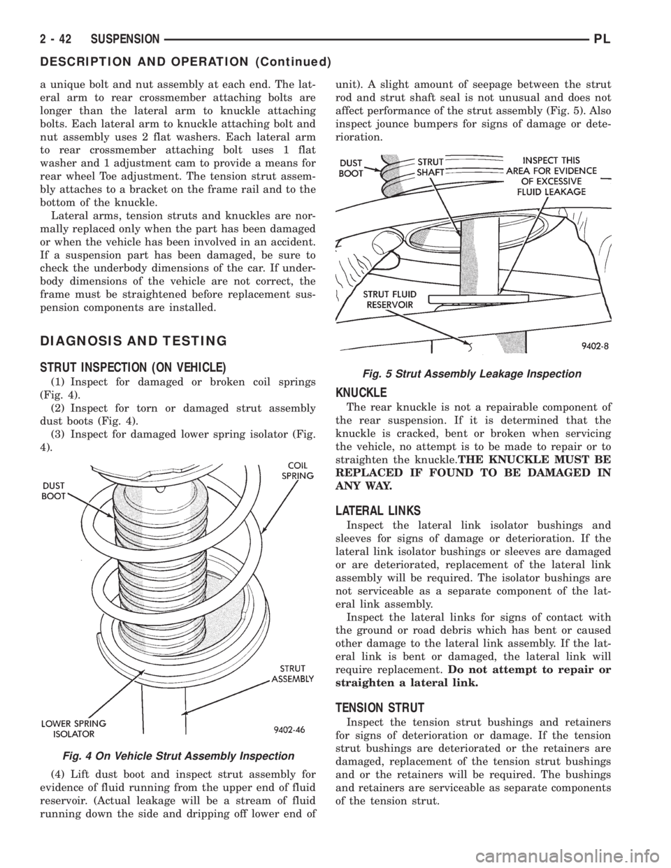
(1) Inspect for damaged or broken coil springs
(Fig. 4).
(2) Inspect for torn or damaged strut assembly
dust boots (Fig. 4).
(3) Inspect for damaged lower spring isolator (Fig.
4).
(4) Lift dust boot and inspect strut assembly for
evidence of fluid running from the upper end of fluid
reservoir. (Actual leakage will be a stream of fluid
running down the side and dripping off lower end ofunit). A slight amount of seepage between the strut
rod and strut shaft seal is not unusual and does not
affect performance of the strut assembly (Fig. 5). Also
inspect jounce bumpers for signs of damage or dete-
rioration.
KNUCKLE
The rear knuckle is not a repairable component of
the rear suspension. If it is determined that the
knuckle is cracked, bent or broken when servicing
the vehicle, no attempt is to be made to repair or to
straighten the knuckle.THE KNUCKLE MUST BE
REPLACED IF FOUND TO BE DAMAGED IN
ANY WAY.
LATERAL LINKS
Inspect the lateral link isolator bushings and
sleeves for signs of damage or deterioration. If the
lateral link isolator bushings or sleeves are damaged
or are deteriorated, replacement of the lateral link
assembly will be required. The isolator bushings are
not serviceable as a separate component of the lat-
eral link assembly.
Inspect the lateral links for signs of contact with
the ground or road debris which has bent or caused
other damage to the lateral link assembly. If the lat-
eral link is bent or damaged, the lateral link will
require replacement.Do not attempt to repair or
straighten a lateral link.
TENSION STRUT
Inspect the tension strut bushings and retainers
for signs of deterioration or damage. If the tension
strut bushings are deteriorated or the retainers are
damaged, replacement of the tension strut bushings
and or the retainers will be required. The bushings
and retainers are serviceable as separate components
of the tension strut.
Fig. 4 On Vehicle Strut Assembly Inspection
Fig. 5 Strut Assembly Leakage Inspection
2 - 42 SUSPENSIONPL
DESCRIPTION AND OPERATION (Continued)
Page 55 of 1200

(7) Remove carpet (if required) from top of strut
tower. Then remove rubber dust shield (Fig. 8) from
top of strut tower, this will allow easier access to
upper strut mount attaching nuts.
(8) Loosen but do not remove the 4 upper strut
mount to strut tower attaching nuts (Fig. 9). Then
while supporting the strut assembly fully remove the
4 strut mount attaching nuts.
(9) Remove strut assembly from knuckle, by slid-
ing knuckle out of clevis bracket on strut assembly.
Then remove strut assembly from vehicle.
INSTALL
(1) Position strut assembly back into vehicle with
the 4 studs on strut mount assembly through holes
in strut tower of vehicle. Install the 4 strut mount to
body attaching nuts (Fig. 9) onto mount studs.
Torque the 4 strut mount to body attaching nuts to
34 N´m (300 in. lbs).(2) Install dust shield into hole on top of strut
tower (Fig. 8). Install carpeting back on top of rear
strut tower.
(3) Raise vehicle.
CAUTION: The knuckle to strut assembly attaching
bolts are serrated and must not be turned during
installation. Install and torque nuts while holding
bolts stationary in knuckle.
(4) Install knuckle assembly into clevis bracket on
strut assembly. Install the 2 clevis bracket to knuckle
assembly attaching bolts and nuts (Fig. 7). Torque
both clevis bracket to knuckle assembly attaching
nuts to 95 N´m (70 ft. lbs.).
(5) Install hydraulic flex hose bracket, on strut
assembly bracket (Fig. 6). Install and securely
tighten bolt attaching hose bracket to strut bracket.
If vehicle is equipped with Anti-Lock brakes, the
wheel speed sensor cable routing clip is also attached
to the strut assembly bracket.
(6) Install wheel and tire assembly on vehicle.
Tighten the wheel mounting stud nuts in proper
sequence until all nuts are torqued to half specifica-
tion. Then repeat tightening sequence to full speci-
fied torque of 135 N´m (100 ft. lbs.).
(7) Lower vehicle to the ground.
(8) Check and reset rear wheel TOE to specifica-
tions if required. Refer to Front And Rear Toe Setting
Procedure in the Wheel Alignment Check And
Adjustment section in this group of the service man-
ual for the required Toe setting procedure.
COIL SPRING
Coil springs are rated separately for each side of
vehicle depending on optional equipment and type of
service. During service procedures where both
springs are removed, mark springs (Chalk, Tape,
etc.) (Fig. 10) to ensure installation in original posi-
tion. If the coils springs require replacement.Be
sure that the springs needing replacement, are
replaced with springs meeting the correct load
and spring rate for the vehicle.
NOTE: During service procedures requiring
removal or installation of a coil spring with Spring
Compressor, Special Tool C-4838. It is required that
the first full top and bottom coil of the coil spring
be captured by the jaws of spring compressor (Fig.
10).
Replacement of the coil spring requires removal of
the strut assembly from the vehicle, and the disas-
sembly of the strut. Refer to strut assembly in the
removal and installation section in this group of the
service manual for the required removal and replace-
ment procedure for the strut assembly. Then refer to
Fig. 8 Dust Shield Removal From Strut Tower
Fig. 9 Strut Mount Attaching Nuts
2 - 44 SUSPENSIONPL
REMOVAL AND INSTALLATION (Continued)
Page 61 of 1200
link mounting bolt at crossmember MUST be
installed, with head of bolt facing rear of vehi-
cle. The long attaching bolt must be used at
rear crossmember and short bolt used at
knuckle.
(1) Install washer on short lateral link attaching
bolt. Then install short lateral link attaching bolt,
into lateral link having the same size bushing
sleeves. Then install lateral link, bolt and washer
onto knuckle as an assembly, with head of bolt facing
to front of vehicle (Fig. 24).
(2) Install lateral link with small and large bush-
ing sleeve, on lateral link attaching bolt in rear
knuckle (Fig. 24).Small bushing sleeve must be
installed on bolt in rear knuckle with large
bushing sleeve at crossmember of vehicle.
(3) Install washer and nut onto lateral link attach-
ing bolt at rear knuckle (Fig. 24).Do not tighten
the lateral link to rear knuckle attaching bolt
at this time.
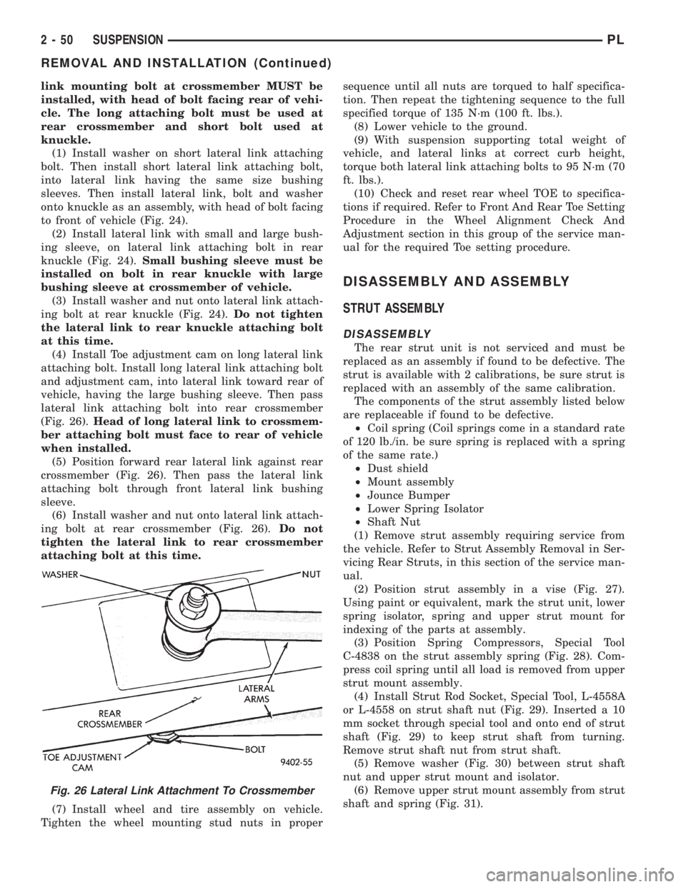
(4) Install Toe adjustment cam on long lateral link
attaching bolt. Install long lateral link attaching bolt
and adjustment cam, into lateral link toward rear of
vehicle, having the large bushing sleeve. Then pass
lateral link attaching bolt into rear crossmember
(Fig. 26).Head of long lateral link to crossmem-
ber attaching bolt must face to rear of vehicle
when installed.
(5) Position forward rear lateral link against rear
crossmember (Fig. 26). Then pass the lateral link
attaching bolt through front lateral link bushing
sleeve.
(6) Install washer and nut onto lateral link attach-
ing bolt at rear crossmember (Fig. 26).Do not
tighten the lateral link to rear crossmember
attaching bolt at this time.
(7) Install wheel and tire assembly on vehicle.
Tighten the wheel mounting stud nuts in propersequence until all nuts are torqued to half specifica-
tion. Then repeat the tightening sequence to the full
specified torque of 135 N´m (100 ft. lbs.).
(8) Lower vehicle to the ground.
(9) With suspension supporting total weight of
vehicle, and lateral links at correct curb height,
torque both lateral link attaching bolts to 95 N´m (70
ft. lbs.).
(10) Check and reset rear wheel TOE to specifica-
tions if required. Refer to Front And Rear Toe Setting
Procedure in the Wheel Alignment Check And
Adjustment section in this group of the service man-
ual for the required Toe setting procedure.
DISASSEMBLY AND ASSEMBLY
STRUT ASSEMBLY
DISASSEMBLY
The rear strut unit is not serviced and must be
replaced as an assembly if found to be defective. The
strut is available with 2 calibrations, be sure strut is
replaced with an assembly of the same calibration.
The components of the strut assembly listed below
are replaceable if found to be defective.
²Coil spring (Coil springs come in a standard rate
of 120 lb./in. be sure spring is replaced with a spring
of the same rate.)
²Dust shield
²Mount assembly
²Jounce Bumper
²Lower Spring Isolator
²Shaft Nut
(1) Remove strut assembly requiring service from
the vehicle. Refer to Strut Assembly Removal in Ser-
vicing Rear Struts, in this section of the service man-
ual.
(2) Position strut assembly in a vise (Fig. 27).
Using paint or equivalent, mark the strut unit, lower
spring isolator, spring and upper strut mount for
indexing of the parts at assembly.
(3) Position Spring Compressors, Special Tool
C-4838 on the strut assembly spring (Fig. 28). Com-
press coil spring until all load is removed from upper
strut mount assembly.
(4) Install Strut Rod Socket, Special Tool, L-4558A
or L-4558 on strut shaft nut (Fig. 29). Inserted a 10
mm socket through special tool and onto end of strut
shaft (Fig. 29) to keep strut shaft from turning.
Remove strut shaft nut from strut shaft.
(5) Remove washer (Fig. 30) between strut shaft
nut and upper strut mount and isolator.
(6) Remove upper strut mount assembly from strut
shaft and spring (Fig. 31).
Fig. 26 Lateral Link Attachment To Crossmember
2 - 50 SUSPENSIONPL
REMOVAL AND INSTALLATION (Continued)