1999 DODGE NEON stop start
[x] Cancel search: stop startPage 719 of 1200
(1) Position the vehicle on a level surface and turn
engine off.
(2) Hoist and support vehicle on safety stands.
Refer to Hoisting and Jacking Recommendations.(3) Remove oil fill cap.
(4) Place a suitable drain pan under crankcase
drain.
(5) Remove drain plug from crankcase and allow
oil to drain into pan. Inspect drain plug threads for
stretching or other damage. Replace drain plug and
gasket if damaged.
(6) Install drain plug in crankcase.
(7) Lower vehicle and fill crankcase with specified
type and amount of engine oil described in this sec-
tion.
(8) Install oil fill cap.
(9) Start engine and inspect for leaks.
(10) Stop engine and inspect oil level.
Fig. 7 Engine Oil Container Standard Notations
9 - 6 ENGINEPL
GENERAL INFORMATION (Continued)
Page 721 of 1200

cause of low compression unless some malfunc-
tion is present.
(11) Clean or replace spark plugs as necessary
and adjust gap as specified in Group 8, Electrical.
Tighten to specifications.
(12) Test resistance of spark plug cables. Refer to
Group 8, Electrical Ignition System Secondary Cir-
cuit Inspection.
(13) Test coil output voltage, primary and second-
ary resistance. Replace parts as necessary. Refer to
Group 8, Electrical Ignition System.
(14) Check fuel pump pressure at idle and differ-
ent RPM ranges. Refer to Group 14, Fuel System for
Specifications.
(15) The air filter elements should be replaced as
specified in Group 0, Lubrication and Maintenance,.
(16) Inspect crankcase ventilation system as out
lined in Group 0, Lubrication and Maintenance. For
emission controls see Group 25, Emission Controls
for service procedures.
(17) Inspect and adjust accessory belt drives refer-
ring to Group 7, Cooling System, Accessory Drive
Belts for proper adjustments.
(18) Road test vehicle as a final test.
CYLINDER COMBUSTION PRESSURE LEAKAGE
TEST
The combustion pressure leakage test provides an
accurate means for determining engine condition.
Combustion pressure leakage testing will detect:
²Exhaust and intake valve leaks (improper seat-
ing).
²Leaks between adjacent cylinders or into water
jacket.
²Any causes for combustion/compression pressure
loss.
WARNING: DO NOT REMOVE THE RADIATOR CAP
WITH THE SYSTEM HOT AND UNDER PRESSURE
BECAUSE SERIOUS BURNS FROM COOLANT CAN
OCCUR.
Check the coolant level and fill as required. DO
NOT install the radiator cap.
Start and operate the engine until it attains nor-
mal operating temperature, then turn the engine
OFF.
Clean spark plug recesses with compressed air.
Remove the spark plugs.
Remove the oil filler cap.
Remove the air cleaner.
Calibrate the tester according to the manufactur-
er's instructions. The shop air source for testing
should maintain 483 kPa (70 psi) minimum, 1 379
kPa (200 psi) maximum and 552 kPa (80 psi) recom-
mended.Perform the test procedures on each cylinder
according to the tester manufacturer's instructions.
While testing, listen for pressurized air escaping
through the throttle body, tailpipe and oil filler cap
opening. Check for bubbles in the radiator coolant.
All gauge pressure indications should be equal,
with no more than 25% leakage.
FOR EXAMPLE:At 552 kPa (80 psi) input pres-
sure, a minimum of 414 kPa (60 psi) should be main-
tained in the cylinder.
LASH ADJUSTER (TAPPET) NOISE DIAGNOSIS
A tappet-like noise may be produced from several
items. Check the following items.
(1) Engine oil level too high or too low. This may
cause aerated oil to enter the adjusters and cause
them to be spongy.
(2) Insufficient running time after rebuilding cylin-
der head. Low speed running up to 1 hour may be
required.
(3) During this time, turn engine off and let set for
a few minutes before restarting. Repeat this several
times after engine has reached normal operating
temperature.
(4) Low oil pressure.
(5) The oil restrictor pressed into the vertical oil
passage to the cylinder head is plugged with debris.
(6) Air ingested into oil due to broken or cracked
oil pump pick up.
(7) Worn valve guides.
(8) Rocker arm ears contacting valve spring
retainer.
(9) Rocker arm loose, adjuster stuck or at maxi-
mum extension and still leaves lash in the system.
(10) Faulty lash adjuster.
a. Check lash adjusters for sponginess while
installed in cylinder head. Depress part of rocker
arm over adjuster. Normal adjusters should feel very
firm. Spongy adjusters can be bottomed out easily.
b. Remove suspected rocker arms (sohc) or lash
adjuster (dohc) and replace.
INSPECTION (ENGINE OIL LEAKS IN GENERAL)
Begin with a through visual inspection of the
engine, particularly at the area of the suspected leak.
If an oil leak source is not readily identifiable, the
following steps should be followed:
(1) Do not clean or degrease the engine at this
time because some solvents may cause rubber to
swell, temporarily stopping the leak.
(2) Add an oil soluble dye (use as recommended by
manufacturer). Start the engine and let idle for
approximately 15 minutes. Check the oil dipstick to
make sure the dye is thoroughly mixed as indicated
with a bright yellow color under a black light.
9 - 8 ENGINEPL
DIAGNOSIS AND TESTING (Continued)
Page 823 of 1200
INSTALLATION
Before installing manifold. Clean all mating sur-
faces. Replace all seals, with new seals. All intakemanifold fasteners and washers are to be discarded
andNEWfasteners and washers are to be used.
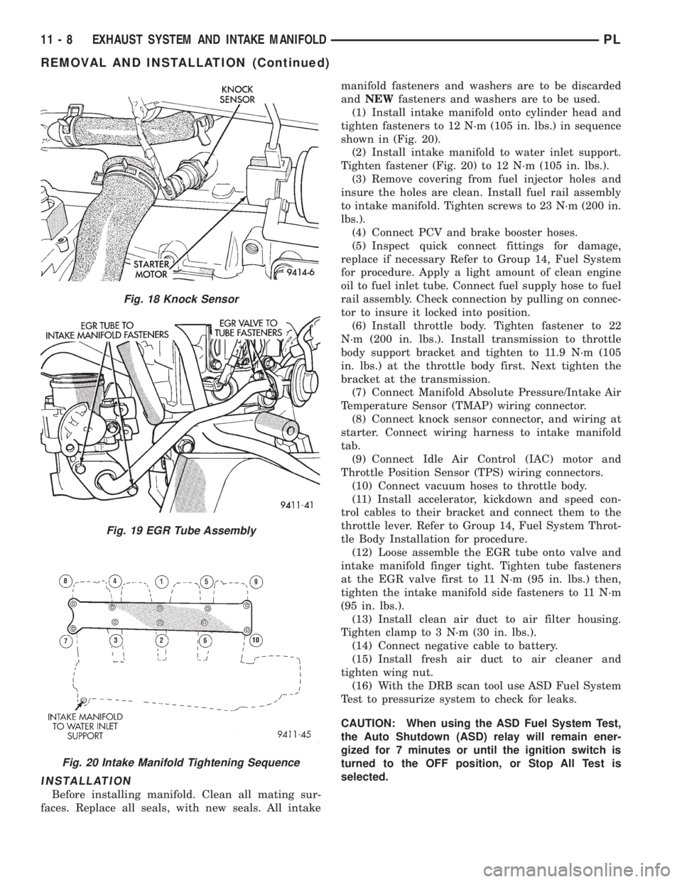
(1) Install intake manifold onto cylinder head and
tighten fasteners to 12 N´m (105 in. lbs.) in sequence
shown in (Fig. 20).
(2) Install intake manifold to water inlet support.
Tighten fastener (Fig. 20) to 12 N´m (105 in. lbs.).
(3) Remove covering from fuel injector holes and
insure the holes are clean. Install fuel rail assembly
to intake manifold. Tighten screws to 23 N´m (200 in.
lbs.).
(4) Connect PCV and brake booster hoses.
(5) Inspect quick connect fittings for damage,
replace if necessary Refer to Group 14, Fuel System
for procedure. Apply a light amount of clean engine
oil to fuel inlet tube. Connect fuel supply hose to fuel
rail assembly. Check connection by pulling on connec-
tor to insure it locked into position.
(6) Install throttle body. Tighten fastener to 22
N´m (200 in. lbs.). Install transmission to throttle
body support bracket and tighten to 11.9 N´m (105
in. lbs.) at the throttle body first. Next tighten the
bracket at the transmission.
(7) Connect Manifold Absolute Pressure/Intake Air
Temperature Sensor (TMAP) wiring connector.
(8) Connect knock sensor connector, and wiring at
starter. Connect wiring harness to intake manifold
tab.
(9) Connect Idle Air Control (IAC) motor and
Throttle Position Sensor (TPS) wiring connectors.
(10) Connect vacuum hoses to throttle body.
(11) Install accelerator, kickdown and speed con-
trol cables to their bracket and connect them to the
throttle lever. Refer to Group 14, Fuel System Throt-
tle Body Installation for procedure.
(12) Loose assemble the EGR tube onto valve and
intake manifold finger tight. Tighten tube fasteners
at the EGR valve first to 11 N´m (95 in. lbs.) then,
tighten the intake manifold side fasteners to 11 N´m
(95 in. lbs.).
(13) Install clean air duct to air filter housing.
Tighten clamp to 3 N´m (30 in. lbs.).
(14) Connect negative cable to battery.
(15) Install fresh air duct to air cleaner and
tighten wing nut.
(16) With the DRB scan tool use ASD Fuel System
Test to pressurize system to check for leaks.
CAUTION: When using the ASD Fuel System Test,
the Auto Shutdown (ASD) relay will remain ener-
gized for 7 minutes or until the ignition switch is
turned to the OFF position, or Stop All Test is
selected.
Fig. 18 Knock Sensor
Fig. 19 EGR Tube Assembly
Fig. 20 Intake Manifold Tightening Sequence
11 - 8 EXHAUST SYSTEM AND INTAKE MANIFOLDPL
REMOVAL AND INSTALLATION (Continued)
Page 826 of 1200

INSTALLATION
Before installing manifolds. Clean all mating sur-
faces. Replace all gaskets, with new.
(1) Assemble lower manifold to upper (if sepa-
rated) and tighten bolts in sequence shown in (Fig.
29) to 28 N´m (250 in. lbs.).
(2) Install intake manifold onto cylinder head and
tighten fasteners to 28 N´m (250 in. lbs.) in sequence
shown in (Fig. 30).
(3) Remove covering from fuel injector holes and
insure the holes are clean. Install fuel rail assembly
to intake manifold. Tighten screws to 23 N´m (200 in.
lbs.).
(4) Connect PCV and brake booster hoses.
(5) Inspect quick connect fittings for damage,
replace if necessary Refer to Group 14, Fuel System
for procedure. Apply a light amount of clean engine
oil to fuel inlet tube. Connect fuel supply hose to fuel
rail assembly. Check connection by pulling on connec-
tor to insure it locked into position.
(6) Connect heater tube and hose to intake mani-
fold.
(7) Connect upper radiator hose and coolant recov-
ery hose.
(8) Connect coolant temperature sensor wiring con-
nector.
(9) Install throttle body. Tighten fastener to 22
N´m (200 in. lbs.).
(10) Connect Manifold Absolute Pressure/Intake
Air Temperature Sensor (TMAP) wiring connector.(11) Connect knock sensor connector and starter
wires. Connect wiring harness to heater tube tab.
(12) Connect Idle Air Control (IAC) motor and
Throttle Position Sensor (TPS) wiring connectors.
(13) Connect vacuum hoses to throttle body.
(14) Install accelerator, kickdown and speed con-
trol cables to their bracket and connect them to the
throttle lever. Refer to Group 14, Fuel System Throt-
tle Body Installation for procedure.
(15) Loose assemble the EGR tube onto valve and
intake manifold finger tight. Tighten tube fasteners
at the EGR valve first to 11 N´m (95 in. lbs.) then,
tighten the intake manifold side fasteners to 11 N´m
(95 in. lbs.).
(16) Install fresh air duct to air filter housing.
Tighten clamp to 3 N´m (25 in. lbs.).
(17) Connect negative cable to battery.
(18) With the DRB scan tool use ASD Fuel System
Test to pressurize system to check for leaks.
CAUTION: When using the ASD Fuel System Test,
the Auto Shutdown (ASD) relay will remain ener-
gized for 7 minutes or until the ignition switch is
turned to the OFF position, or Stop All Test is
selected.
EXHAUST MANIFOLD
REMOVAL
(1) Remove air cleaner assembly and bracket.
(2) Remove exhaust manifold heat shield (Fig. 31).
(3) Disconnect upstream heated oxygen sensor con-
nector.
Fig. 29 Lower Intake Manifold to Upper Tightening
Sequence
Fig. 30 Intake Manifold To Cylinder Head Tightening
Sequence
Fig. 31 Exhaust Manifold Heat Shield
PLEXHAUST SYSTEM AND INTAKE MANIFOLD 11 - 11
REMOVAL AND INSTALLATION (Continued)
Page 911 of 1200
Rectangular pumping vanes in the shaft driven
rotor, move power steering fluid from the intake to
the cam ring pressure cavities of the power steering
pump. As the rotor begins to turn, centrifugal force
throws the vanes against the inside surface of the
cam ring to pickup residual oil. This oil is then forced
into the high pressure area. As more oil is picked up
by the vanes, the additional oil is forced into the cav-
ities of the thrust plate through two crossover holes
in the cam ring and pressure plate. The crossover
holes empty into the high pressure area between the
pressure plate and the housing end cover.
As the high pressure area is filled, oil flows under
the vanes in the rotor slots, forcing the vanes to fol-
low the inside surface of the cam ring. As the vanes
reach the restricted area of the cam ring, oil is forced
out from between the vanes. When excess oil flow is
generated during high-speed operation, a regulated
amount of oil returns to the pump intake side
through a flow control valve. The flow control valve
reduces the power required to drive the pump and
holds down temperature build-up.
When steering conditions exceed maximum pres-
sure requirements, such as when the wheels are
turned against the stops. The pressure built up in
the steering gear exerts pressure on the spring end of
the flow control valve. The high pressure lifts the
relief valve ball from its seat and allows oil to flow
through a trigger orifice located in the outlet fitting.
This reduces pressure on the spring end of the flow
control valve which then opens and allows the oil to
return to the intake side of the pump. This action
limits maximum pressure output of the pump to a
safe level.
Under normal power steering pump operating con-
ditions, pressure requirements of the pump are below
maximum, causing the pressure relief valve to
remain closed.
DIAGNOSIS AND TESTING
POWER STEERING SYSTEM TEST PROCEDURE
The following procedure can be used to test the
operation of the power steering system on the vehi-
cle. This test will provide the flow rate of the power
steering pump along with the maximum relief pres-
sure. This test is to be performed any time a power
steering system problem is present to determine if
the power steering pump or power steering gear is
not functioning properly. The following pressure and
flow test is performed using Pressure/Flow Tester,
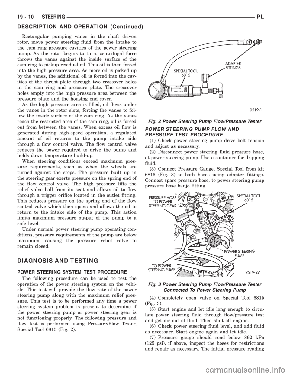
Special Tool 6815 (Fig. 2).
POWER STEERING PUMP FLOW AND
PRESSURE TEST PROCEDURE
(1) Check power steering pump drive belt tension
and adjust as necessary.
(2) Disconnect power steering fluid pressure hose,
at power steering pump. Use a container for dripping
fluid.
(3) Connect Pressure Gauge, Special Tool from kit
6815 (Fig. 3) to both hoses using adapter fittings.
Connect spare pressure hose, to power steering pump
pressure hose banjo fitting.
(4) Completely open valve on Special Tool 6815
(Fig. 3).
(5) Start engine and let idle long enough to circu-
late power steering fluid through flow/pressure test
and get air out of fluid. Then shut off engine.
(6) Check power steering fluid level, and add fluid
as necessary. Start engine again and let idle.
(7) Pressure gauge should read below 862 kPa
(125 psi), if above, inspect the hoses for restrictions
and repair as necessary. The initial pressure reading
Fig. 2 Power Steering Pump Flow/Pressure Tester
Fig. 3 Power Steering Pump Flow/Pressure Tester
Connected To Power Steering Pump
19 - 10 STEERINGPL
DESCRIPTION AND OPERATION (Continued)
Page 912 of 1200
should be in the range of 345-552 kPa (50-80 psi).
The flow meter should read between 1.3 and 1.4
GPM
CAUTION: The following test procedure involves
testing power steering pump maximum pressure
output and flow control valve operation. Do not
leave valve closed for more than 5 seconds as the
pump could be damaged.
(8) Close valve fully three times and record high-
est pressure indicated each time.All three read-
ings must be above specifications and within
345 kPa (50 psi) of each other.
NOTE: Power steering pump maximum relief pres-
sure is 8240 to 8920 kPa (1195 to 1293 psi.).
²If power steering pump pressures above specifi-
cations but not within 345 kPa (50 psi) of each other,
then replace power steering pump.
²If pressures within 345 kPa (50 psi) of each
other but below specifications, then replace power
steering pump.
CAUTION: Do not force the pump to operate
against the stops for more than 5 seconds at a time
because, pump damage will result.
(9) Open test valve. Turn steering wheel to the
extreme left and right positions until against the
stops, recording the highest indicated pressure at
each position. Compare pressure gauge readings to
power steering pump specifications. If highest output
pressures are not the same against either stop, the
steering gear is leaking internally and must be
replaced.
SERVICE PROCEDURES
POWER STEERING SYSTEM FLUID LEVEL CHECK
WARNING: FLUID LEVEL SHOULD BE CHECKED
WITH ENGINE OFF TO PREVENT INJURY FROM
MOVING PARTS. DO NOT USE AUTOMATIC TRANS-
MISSION FLUID IN THE POWER STEERING SYS-
TEM. DO NOT OVERFILL THE POWER STEERING
SYSTEM.
Wipe reservoir filler cap free of dirt. Then check
fluid level. The dipstick should indicate COLD when
fluid is at normal ambient temperature, approxi-
mately 21ÉC to 27ÉC (70ÉF to 80ÉF). In all pumps add
fluid as necessary, use onlyMopar Power Steering
Fluid, or equivalent. DO NOT USE ANY TYPE
OF AUTOMATIC TRANSMISSION FLUID.
POWER STEERING PUMP INITIAL OPERATION
CAUTION: The fluid level should be checked with
engine off to prevent injury from moving compo-
nents. Use only MoparTPower Steering Fluid. Do
not use automatic transmission fluid. Do not over-
fill.
Wipe filler cap clean, then check the fluid level.
The dipstick should indicateFULL COLDwhen the
fluid is at normal temperature of approximately 21ÉC
to 27ÉC (70ÉF to 80ÉF).
(1) Fill the pump fluid reservoir to the proper level
and let the fluid settle for at least two (2) minutes.
(2) Start the engine and let run for a few seconds.
Then turn the engine off.
(3) Add fluid if necessary. Repeat the above proce-
dure until the fluid level remains constant after run-
ning the engine.
(4) Raise the front wheels off the ground.
(5) Start the engine. Slowly turn the steering
wheel right and left, lightly contacting the wheel
stops.
(6) Add power steering fluid if necessary.
(7) Lower the vehicle and turn the steering wheel
slowly from lock to lock.
(8) Stop the engine. Check the fluid level and refill
as required.
(9) If the fluid is extremely foamy, allow the vehi-
cle to stand a few minutes and repeat the above pro-
cedure.
POWER STEERING PUMP FLOW CONTROL VALVE
SEAL
The power steering pump does not require removal
from the engine for removal and replacement of the
flow control valve fitting O-Ring.
REMOVE
(1) Remove the power steering fluid pressure hose
from the power steering pump pressure fitting (Fig.
4).
(2) Remove the flow control valve fitting from the
power steering pump housing (Fig. 5).Prevent flow
control valve and spring from sliding out of
housing bore.
(3) Remove and discard O-ring seal from fitting.
INSTALL
(1) If necessary, clean and install flow control
valve and spring in pump housing bore.
(2) Install new O-ring seal on fitting.
(3) Install fitting in pump housing and tighten to
75 N´m (55 ft. lbs.)
(4) Install power steering fluid pressure hose on
flow control valve fitting.
PLSTEERING 19 - 11
DIAGNOSIS AND TESTING (Continued)
Page 914 of 1200
REMOVE
CAUTION: When removing and installing the
power steering pressure switch, the use of a 7/8
inch deep well socket is required. The deep well
socket will prevent damage to the plastic, electrical
connector area, of the power steering pressure
switch.
(1) Disconnect negative battery cable from the neg-
ative post of the battery. Be sure cable is isolated
from negative post on battery.
(2) Raise vehicle.
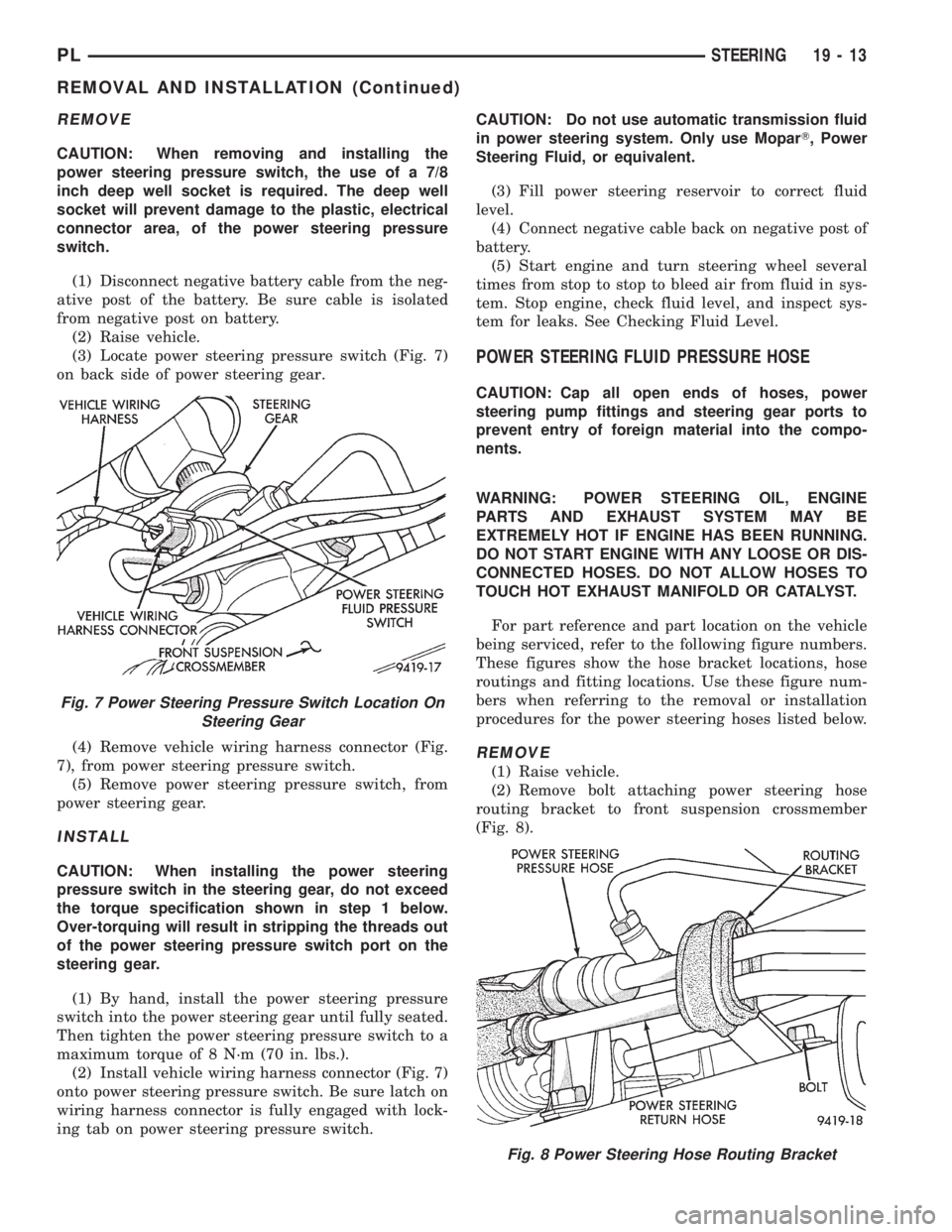
(3) Locate power steering pressure switch (Fig. 7)
on back side of power steering gear.
(4) Remove vehicle wiring harness connector (Fig.
7), from power steering pressure switch.
(5) Remove power steering pressure switch, from
power steering gear.
INSTALL
CAUTION: When installing the power steering
pressure switch in the steering gear, do not exceed
the torque specification shown in step 1 below.
Over-torquing will result in stripping the threads out
of the power steering pressure switch port on the
steering gear.
(1) By hand, install the power steering pressure
switch into the power steering gear until fully seated.
Then tighten the power steering pressure switch to a
maximum torque of 8 N´m (70 in. lbs.).
(2) Install vehicle wiring harness connector (Fig. 7)
onto power steering pressure switch. Be sure latch on
wiring harness connector is fully engaged with lock-
ing tab on power steering pressure switch.CAUTION: Do not use automatic transmission fluid
in power steering system. Only use MoparT, Power
Steering Fluid, or equivalent.
(3) Fill power steering reservoir to correct fluid
level.
(4) Connect negative cable back on negative post of
battery.
(5) Start engine and turn steering wheel several
times from stop to stop to bleed air from fluid in sys-
tem. Stop engine, check fluid level, and inspect sys-
tem for leaks. See Checking Fluid Level.
POWER STEERING FLUID PRESSURE HOSE
CAUTION: Cap all open ends of hoses, power
steering pump fittings and steering gear ports to
prevent entry of foreign material into the compo-
nents.
WARNING: POWER STEERING OIL, ENGINE
PARTS AND EXHAUST SYSTEM MAY BE
EXTREMELY HOT IF ENGINE HAS BEEN RUNNING.
DO NOT START ENGINE WITH ANY LOOSE OR DIS-
CONNECTED HOSES. DO NOT ALLOW HOSES TO
TOUCH HOT EXHAUST MANIFOLD OR CATALYST.
For part reference and part location on the vehicle
being serviced, refer to the following figure numbers.
These figures show the hose bracket locations, hose
routings and fitting locations. Use these figure num-
bers when referring to the removal or installation
procedures for the power steering hoses listed below.
REMOVE
(1) Raise vehicle.
(2) Remove bolt attaching power steering hose
routing bracket to front suspension crossmember
(Fig. 8).
Fig. 7 Power Steering Pressure Switch Location On
Steering Gear
Fig. 8 Power Steering Hose Routing Bracket
PLSTEERING 19 - 13
REMOVAL AND INSTALLATION (Continued)
Page 916 of 1200
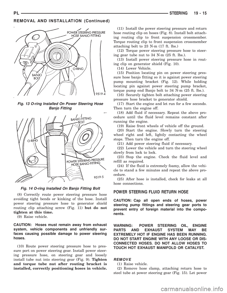
(8) Correctly route power steering pressure hose
avoiding tight bends or kinking of the hose. Install
power steering pressure hose to generator shield
routing clip attaching screw (Fig. 11)but do not
tighten at this time.
(9) Raise vehicle.
CAUTION: Hoses must remain away from exhaust
system, vehicle components and unfriendly sur-
faces causing possible damage to power steering
hoses.
(10) Route power steering pressure hose to pres-
sure port on power steering gear. Install power steer-
ing pressure hose, on steering gear and loosely
install tube nut into steering gear (Fig. 9).Tighten
and torque tube nut after routing bracket is
installed, correctly positioning hoses in vehicle.(11) Install the power steering pressure and return
hose routing clip on hoses (Fig. 8). Install bolt attach-
ing routing clip to front suspension crossmember.
Torque routing clip to front suspension crossmember
attaching bolt to 23 N´m (17 ft. lbs.)
(12) Torque power steering pressure hose to steer-
ing gear tube nut to 34 N´m (25 ft. lbs.).
(13) Install power steering pressure hose in rout-
ing clip on generator shield (Fig. 10).
(14) Lower Vehicle.
(15) Position locating pin on power steering pres-
sure hose banjo fitting so it is against power steering
pump mounting bracket (Fig. 12). While holding
locating pin against power steering pump bracket,
torque pump end Banjo bolt to 34 N´m (25 ft. lbs.).
(16) Securely tighten bolt attaching power steering
pressure hose bracket to generator shield.
(17) Start the engine and let run for a few seconds.
Then turn the engine off.
(18) Add fluid if necessary. Repeat the above pro-
cedure until the fluid level remains constant after
running the engine.
(19) Raise front wheels of vehicle off the ground.
(20) Start the engine. Slowly turn the steering
wheel right and left, lightly contacting the wheel
stops. Then turn the engine off.
(21) Add power steering fluid if necessary.
(22) Lower the vehicle and turn the steering wheel
slowly from lock to lock.
(23) Stop the engine. Check the fluid level and
refill as required.
(24) If the fluid is extremely foamy, allow the vehi-
cle to stand a few minutes and repeat the above pro-
cedure.
(25) After hose is installed, check for leaks at all
hose connections.POWER STEERING FLUID RETURN HOSE
CAUTION: Cap all open ends of hoses, power
steering pump fittings and steering gear ports to
prevent entry of foreign material into the compo-
nents.
WARNING: POWER STEERING OIL, ENGINE
PARTS AND EXHAUST SYSTEM MAY BE
EXTREMELY HOT IF ENGINE HAS BEEN RUNNING.
DO NOT START ENGINE WITH ANY LOOSE OR DIS-
CONNECTED HOSES. DO NOT ALLOW HOSES TO
TOUCH HOT EXHAUST MANIFOLD OR CATALYST.
REMOVE
(1) Raise vehicle.
(2) Remove hose clamp, attaching return hose to
steel tube at power steering gear (Fig. 15). Let power
Fig. 13 O-ring Installed On Power Steering Hose
Banjo Fitting
Fig. 14 O-ring Installed On Banjo Fitting Bolt
PLSTEERING 19 - 15
REMOVAL AND INSTALLATION (Continued)