1999 DODGE NEON radio antenna
[x] Cancel search: radio antennaPage 288 of 1200
AUDIO SYSTEM
CONTENTS
page page
GENERAL INFORMATION
INTRODUCTION......................... 1
DESCRIPTION AND OPERATION
INTERFERENCE ELIMINATION.............. 1
DIAGNOSIS AND TESTING
ANTENNA.............................. 3
AUDIO DIAGNOSTIC TEST PROCEDURES..... 1BENCH TEST FOR ANTENNA MALFUNCTION . . 3
REMOVAL AND INSTALLATION
ANTENNA.............................. 3
FRONT DOOR SPEAKER................... 4
INSTRUMENT PANEL SPEAKER............. 4
RADIO................................. 4
REAR SHELF SPEAKER(S)................. 5
GENERAL INFORMATION
INTRODUCTION
Operating instructions for the factory installed
audio systems can be found in the Owner's Manual
provided with the vehicle.
The vehicles are equipped with an Interior (Igni-
tion Off Draw) fuse in the Power Distribution Center
located in the engine compartment. After the Interior
(IOD) fuse or battery has been disconnected the clock
will require resetting.
DESCRIPTION AND OPERATION
INTERFERENCE ELIMINATION
The radio utilizes a ground wire plugged on to a
blade terminal and is bolted to the radio chassis.
Both connector and terminal should be securely
attached. The engine has three separate ground
straps to suppress ignition noise which may interfere
with radio reception.
²Left engine mount clip on strap
²Engine to shock tower reinforcement
²Rear strut to body, clip-on strap
Inductive type spark plug cables in the high ten-
sion circuit of the ignition system complete the inter-
ference suppression. Faulty or deteriorated spark
plug wires should be replaced.
In addition, there is a capacitor mounted on the
cylinder head which also helps suppress ignition
noise.
DIAGNOSIS AND TESTING
AUDIO DIAGNOSTIC TEST PROCEDURES
CAUTION: The CD player will only operate between
approximate temperatures of -23ÉC and +65ÉC (-10ÉF
and +145ÉF).
Whenever a radio malfunction occurs;
(1) First check FUSES:
(a) Power Distribution Center (PDC), Interior
lamp fuse, M1 - Radio Memory Feed
(b) Fuse Block:
(I) Fuse 12, Illumination in the fuse block
(II) Fuse 16, Ignition feed in the fuse block
NOTE: The vehicles are shipped with the INTERIOR
LAMP fuse disconnected.
(2) Verify, the radio wire harness are properly con-
nected before starting normal diagnosis and repair
procedures. Refer to Audio Diagnosis table and/or
Group 8W, Wiring Diagrams, Radio Section.
PLAUDIO SYSTEM 8F - 1
Page 289 of 1200
AUDIO SYSTEM DIAGNOSIS
CONDITION POSSIBLE CAUSE CORRECTION
NO AUDIO. 1. FUSE FAULTY.
2. RADIO CONNECTOR
FAULTY.
3. WIRING FAULTY.
4. GROUND FAULTY.
5. RADIO FAULTY.
6. SPEAKERS FAULTY.1. CHECK RADIO FUSES IN FUSEBLOCK MODULE. REPLACE
FUSES, IF REQUIRED.
2. CHECK FOR LOOSE OR CORRODED RADIO CONNECTOR.
REPAIR, IF REQUIRED.
3. CHECK FOR BATTERY VOLTAGE AT RADIO CONNECTOR.
REPAIR WIRING, IF REQUIRED.
4. CHECK FOR CONTINUITY BETWEEN RADIO CHASSIS AND
A KNOWN GOOD GROUND. THERE SHOULD BE
CONTINUITY. REPAIR GROUND, IF REQUIRED.
5. EXCHANGE OR REPLACE RADIO, IF REQUIRED.
6. SEE SPEAKER DIAGNOSIS, IN THIS GROUP.
NO DISPLAY. 1. FUSE FAULTY.
2. RADIO CONNECTOR
FAULTY.
3. WIRING FAULTY.
4. GROUND FAULTY.
5. RADIO FAULTY.1. CHECK RADIO FUSES IN FUSEBLOCK MODULE. REPLACE
FUSES, IF REQUIRED.
2. CHECK FOR LOOSE OR CORRODED RADIO CONNECTOR.
REPAIR, IF REQUIRED.
3. CHECK FOR BATTERY VOLTAGE AT RADIO CONNECTOR.
REPAIR WIRING, IF REQUIRED.
4. CHECK FOR CONTINUITY BETWEEN RADIO CHASSIS AND
A KNOWN GOOD GROUND. THERE SHOULD BE
CONTINUITY. REPAIR GROUND, IF REQUIRED.
5. EXCHANGE OR REPLACE RADIO, IF REQUIRED.
NO MEMORY. 1. FUSE FAULTY.
2. RADIO CONNECTOR
FAULTY.
3. WIRING FAULTY.
4. GROUND FAULTY.
5. RADIO FAULTY.1. CHECK IGNITION-OFF DRAW FUSE. REPLACE FUSE, IF
REQUIRED.
2. CHECK FOR LOOSE OR CORRODED RADIO CONNECTOR.
REPAIR, IF REQUIRED.
3. CHECK FOR BATTERY VOLTAGE AT RADIO CONNECTOR.
REPAIR WIRING, IF REQUIRED.
4. CHECK FOR CONTINUITY BETWEEN RADIO CHASSIS AND
A KNOWN GOOD GROUND. THERE SHOULD BE
CONTINUITY. REPAIR GROUND, IF REQUIRED.
5. EXCHANGE OR REPLACE RADIO, IF REQUIRED.
POOR RADIO
RECEPTION.1. ANTENNA FAULTY.
2. GROUND FAULTY.
3. RADIO FAULTY.1. SEE ANTENNA DIAGNOSIS, IN THIS GROUP. REPAIR OR
REPLACE ANTENNA, IF REQUIRED.
2. CHECK FOR CONTINUITY BETWEEN RADIO CHASSIS AND
A KNOWN GOOD GROUND. THERE SHOULD BE
CONTINUITY. REPAIR GROUND, IF REQUIRED..
3. EXCHANGE OR REPLACE RADIO, IF REQUIRED.
NO/POOR TAPE
OPERATION.1. FAULTY TAPE.
2. FOREIGN OBJECTS
BEHIND TAPE DOOR.
3. DIRTY CASSETTE
TAPE HEAD.
4. FAULTY TAPE DECK.1. INSERT KNOWN GOOD TAPE AND TEST OPERATION.
2. REMOVE FOREIGN OBJECTS AND TEST OPERATION.
3. CLEAN HEAD WITH MOPAR CASSETTE HEAD CLEANER.
4. EXCHANGE OR REPLACE RADIO, IF REQUIRED.
NO COMPACT
DISC
OPERATION1. FAULTY CD.
2. FOREIGN MATERIAL
ON CD.
3. CONDENSATION ON
CD OR OPTICS.
4. FAULTY CD PLAYER.1. INSERT KNOWN GOOD CD AND TEST OPERATION.
2. CLEAN CD AND TEST OPERATION.
3. ALLOW TEMPERATURE OF VEHICLE INTERIOR TO
STABILIZE AND TEST OPERATION.
4. EXCHANGE OR REPLACE RADIO, IF REQUIRED.
8F - 2 AUDIO SYSTEMPL
DIAGNOSIS AND TESTING (Continued)
Page 290 of 1200
ANTENNA
The antenna has a short cable which connects into
the instrument panel harness. The connection is
made on the right side of the instrument panel.
Antenna performance may be tested by substitut-
ing a known good antenna. It is also possible to
check short or open circuits with an ohmmeter or
continuity light once the antenna cable is discon-
nected from the radio as follows:
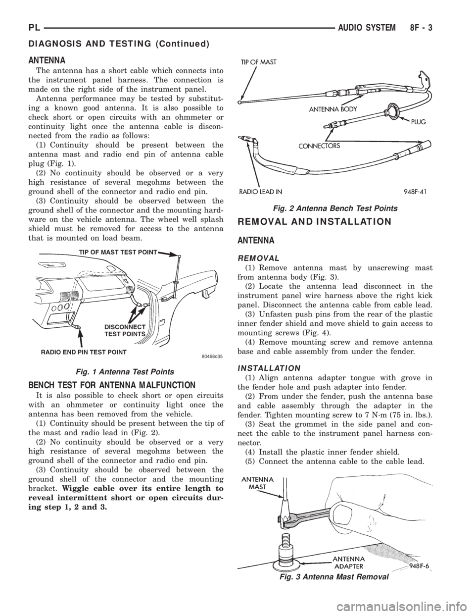
(1) Continuity should be present between the
antenna mast and radio end pin of antenna cable
plug (Fig. 1).
(2) No continuity should be observed or a very
high resistance of several megohms between the
ground shell of the connector and radio end pin.
(3) Continuity should be observed between the
ground shell of the connector and the mounting hard-
ware on the vehicle antenna. The wheel well splash
shield must be removed for access to the antenna
that is mounted on load beam.
BENCH TEST FOR ANTENNA MALFUNCTION
It is also possible to check short or open circuits
with an ohmmeter or continuity light once the
antenna has been removed from the vehicle.
(1) Continuity should be present between the tip of
the mast and radio lead in (Fig. 2).
(2) No continuity should be observed or a very
high resistance of several megohms between the
ground shell of the connector and radio end pin.
(3) Continuity should be observed between the
ground shell of the connector and the mounting
bracket.Wiggle cable over its entire length to
reveal intermittent short or open circuits dur-
ing step 1, 2 and 3.
REMOVAL AND INSTALLATION
ANTENNA
REMOVAL
(1) Remove antenna mast by unscrewing mast
from antenna body (Fig. 3).
(2) Locate the antenna lead disconnect in the
instrument panel wire harness above the right kick
panel. Disconnect the antenna cable from cable lead.
(3) Unfasten push pins from the rear of the plastic
inner fender shield and move shield to gain access to
mounting screws (Fig. 4).
(4) Remove mounting screw and remove antenna
base and cable assembly from under the fender.
INSTALLATION
(1) Align antenna adapter tongue with grove in
the fender hole and push adapter into fender.
(2) From under the fender, push the antenna base
and cable assembly through the adapter in the
fender. Tighten mounting screw to 7 N´m (75 in. lbs.).
(3) Seat the grommet in the side panel and con-
nect the cable to the instrument panel harness con-
nector.
(4) Install the plastic inner fender shield.
(5) Connect the antenna cable to the cable lead.
Fig. 2 Antenna Bench Test Points
Fig. 3 Antenna Mast Removal
Fig. 1 Antenna Test Points
PLAUDIO SYSTEM 8F - 3
DIAGNOSIS AND TESTING (Continued)
Page 291 of 1200
RADIO
REMOVAL
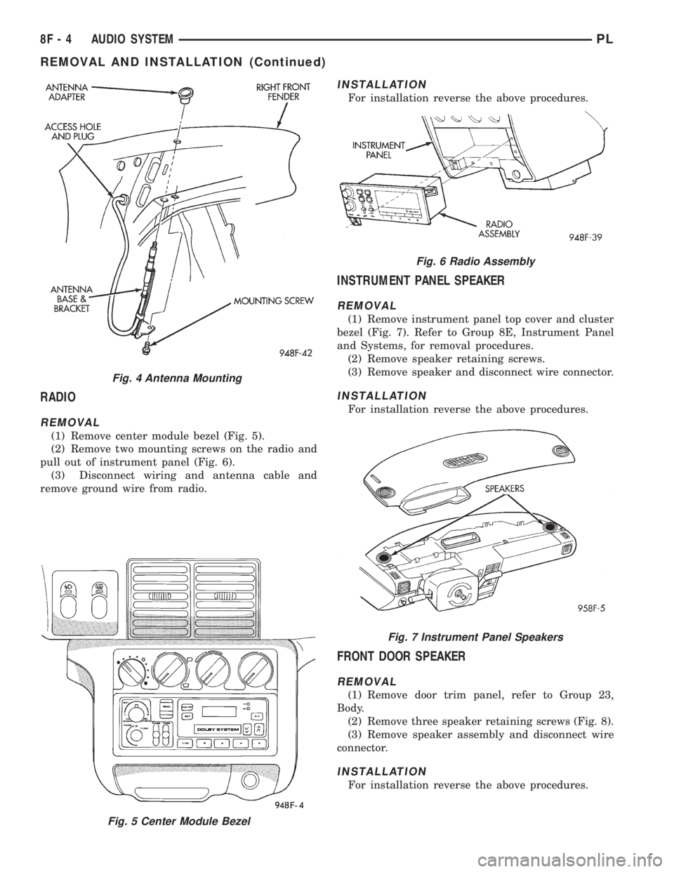
(1) Remove center module bezel (Fig. 5).
(2) Remove two mounting screws on the radio and
pull out of instrument panel (Fig. 6).
(3) Disconnect wiring and antenna cable and
remove ground wire from radio.
INSTALLATION
For installation reverse the above procedures.
INSTRUMENT PANEL SPEAKER
REMOVAL
(1) Remove instrument panel top cover and cluster
bezel (Fig. 7). Refer to Group 8E, Instrument Panel
and Systems, for removal procedures.
(2) Remove speaker retaining screws.
(3) Remove speaker and disconnect wire connector.
INSTALLATION
For installation reverse the above procedures.
FRONT DOOR SPEAKER
REMOVAL
(1) Remove door trim panel, refer to Group 23,
Body.
(2) Remove three speaker retaining screws (Fig. 8).
(3) Remove speaker assembly and disconnect wire
connector.
INSTALLATION
For installation reverse the above procedures.
Fig. 5 Center Module Bezel
Fig. 4 Antenna Mounting
Fig. 6 Radio Assembly
Fig. 7 Instrument Panel Speakers
8F - 4 AUDIO SYSTEMPL
REMOVAL AND INSTALLATION (Continued)
Page 410 of 1200

8W-02 COMPONENT INDEX
Component Page
A/C Compressor Clutch..................8W-42
A/C Compressor Clutch Relay.............8W-42
A/C Cycling Switch.....................8W-42
A/C Heater Blower Motor................8W-42
A/C Heater Control.....................8W-42
A/C Pressure Switches...................8W-42
ABS Warning Lamp Relay................8W-35
Airbag Control Module...................8W-43
Airbags..............................8W-43
Antenna..............................8W-47
Ash Receiver Lamp.....................8W-44
Automatic Shut Down Relay..............8W-30
Back-Up Lamp Switch...................8W-51
Back-Up Lamps........................8W-51
Battery..............................8W-20
Battery Temperature Sensor..............8W-30
Blower Motor Resistor Block..............8W-42
Brake Warning Lamp Switch...........8W-40, 50
Camshaft Position Sensor................8W-30
Center High Mounted Stop Lamp..........8W-51
Cigar Lighter Relay.....................8W-41
Cigar Lighter/Power Outlet...............8W-41
Circuit Breakers.......................8W-11
Clockspring.....................8W-30, 41, 61
Clutch Pedal Position Switch...........8W-10, 21
Combination Flasher....................8W-52
Controller Anti-Lock Brake...............8W-35
Crankshaft Position Sensor...............8W-30
Data Link Connector....................8W-30
Daytime Running Lamp Module...........8W-50
Diode No. 1........................8W-15, 42
Diode No. 2......................8W-10, 11, 44
Diode No. 3......................8W-11,44,70
Dome Lamp...........................8W-44
Door Ajar Switches.....................8W-44
Door Jamb Switches....................8W-44
Door Lock Motors......................8W-61
Door Lock Motors......................8W-61
Door Lock Switches.....................8W-61
Duty Cycle Evap/Purge Solenoid...........8W-30
EGR Transducer Solenoid................8W-30
Engine Coolant Temperature Sensor........8W-30
Engine Oil Pressure Switch...............8W-40
Engine Starter Motor....................8W-21
Engine Starter Motor Relay...............8W-21
Fog Lamp Relays....................8W-50, 51
Fog Lamp Switches..................8W-50, 51
Fog Lamps.........................8W-50, 51
Fuel Injectors..........................8W-30
Fuel Pump Module.....................8W-30
Fuel Pump Relay.......................8W-30
Fuse Block............................8W-11Component Page
Fuses (FB)............................8W-11
Fuses (PDC)...........................8W-10
Fusible Link........................8W-20, 21
Generator.............................8W-20
Glove Box Lamp And Switch..............8W-44
Grounds..............................8W-15
Halo Lamp............................8W-44
Headlamp Dimmer And Optical Horn Switch .8W-50
Headlamp Leveling Motors...............8W-50
Headlamp Leveling Switch...............8W-50
Headlamp Switch.......................8W-50
Headlamps............................8W-50
High Speed Warning Module..............8W-40
Horn Relay...........................8W-41
Horn Switches.........................8W-41
Horns................................8W-41
IAT/Map Sensor........................8W-30
Idle Air Control Motor...................8W-30
Ignition Coil Pack......................8W-30
Ignition Switch........................8W-10
Illumination Lamps.....................8W-40
Immobilizer...........................8W-61
Immobilizer Engine Sensor............8W-30, 61
Indicator Lamps........................8W-40
Instrument Cluster.....................8W-40
Intermittent Wipe/Wash Switch............8W-53
Key-In Switch.........................8W-40
Knock Sensor..........................8W-30
License Lamps.........................8W-51
Map/Reading Lamps....................8W-44
Noise Supressor.....................8W-10, 30
Oxygen Sensors........................8W-30
Park Brake Switch...................8W-40, 50
Park/Neutral Position Switch...........8W-30, 51
Park/Turn Signal Lamps..............8W-50, 52
Power Distribution Center................8W-10
Power Folding Mirror Relay...............8W-62
Power Mirror Fuse Holder................8W-62
Power Mirrors.........................8W-62
Power Steering Pressure Switch...........8W-30
Power Sunroof Motor....................8W-64
Power Window Motors...................8W-60
Power Window Switches.................8W-60
Powertrain Control Module...............8W-30
PRNDL Lamp.........................8W-44
Radiator Fan Motor.....................8W-42
Radio................................8W-47
Rear Window Defogger..................8W-48
Rear Window Defogger Switch.............8W-48
Remote Keyless Entry Module.............8W-61
Remote Keyless Entry Program
Module Connector....................8W-61
PL8W - 02 COMPONENT INDEX 8W - 02 - 1
Page 530 of 1200
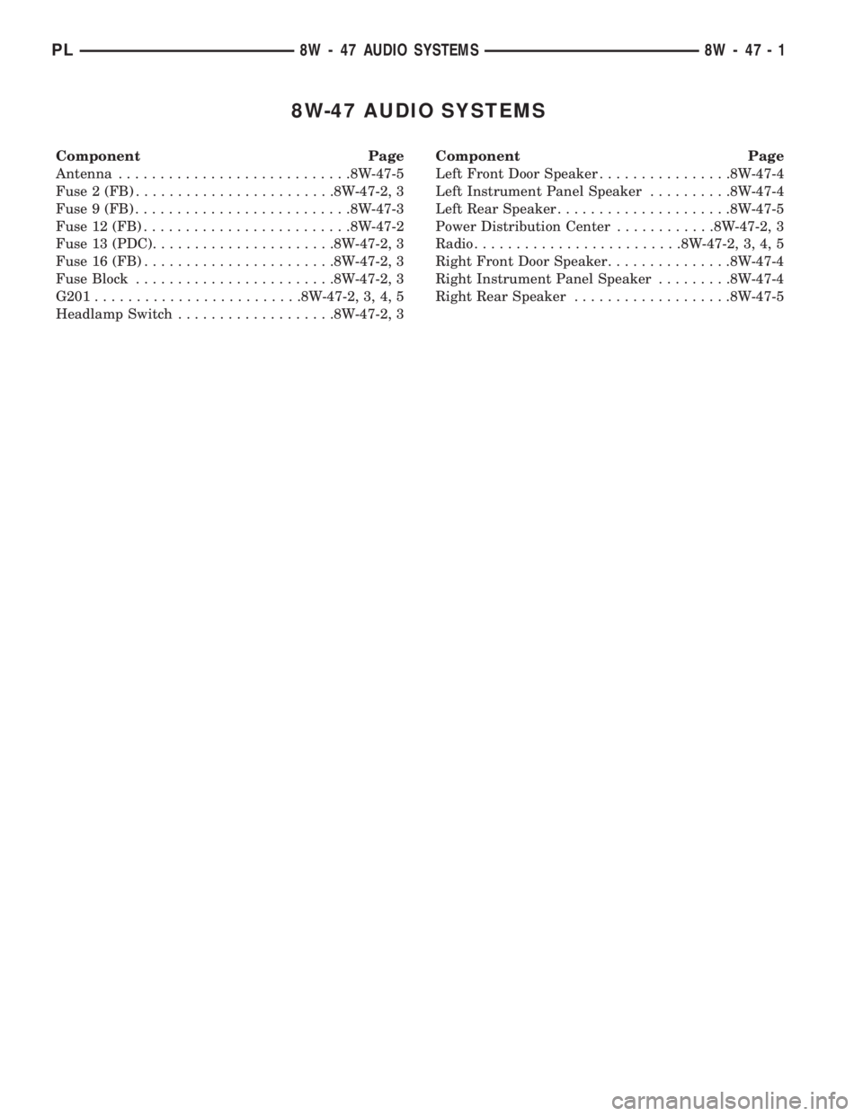
8W-47 AUDIO SYSTEMS
Component Page
Antenna............................8W-47-5
Fuse 2 (FB)........................8W-47-2, 3
Fuse 9 (FB)..........................8W-47-3
Fuse 12 (FB).........................8W-47-2
Fuse 13 (PDC)......................8W-47-2, 3
Fuse 16 (FB).......................8W-47-2, 3
Fuse Block........................8W-47-2, 3
G201.........................8W-47-2, 3, 4, 5
Headlamp Switch...................8W-47-2, 3Component Page
Left Front Door Speaker................8W-47-4
Left Instrument Panel Speaker..........8W-47-4
Left Rear Speaker.....................8W-47-5
Power Distribution Center............8W-47-2, 3
Radio.........................8W-47-2, 3, 4, 5
Right Front Door Speaker...............8W-47-4
Right Instrument Panel Speaker.........8W-47-4
Right Rear Speaker...................8W-47-5
PL8W - 47 AUDIO SYSTEMS 8W - 47 - 1
Page 534 of 1200

2
1
SPEAKER REAR
RIGHT LEFT
REAR
SPEAKER
1 2
C126C13C17C1
RADIO
X51
20
BR/YL
X51
20
BR/YLX57
20
BR/LB
X57
20
BR/LBX52
20
DB/WT
X52
20
DB/WTX58
20
DB/OR
X58
20
DB/OR 19 6 13 8
Z9
14
BK
G201
ANTENNA
INPUT
ANTENNA
LEFT
REAR
SPEAKER
(+) (+)SPEAKERREAR RIGHT
(-) SPEAKERREAR RIGHT
(-) SPEAKERREARLEFT
BUILT-UP-EXPORTEXCEPT
BUILT-UP-EXPORTBUILT-UP-EXPORT EXCEPT
BUILT-UP-EXPORT
BUILT-UP-EXPORT EXCEPT
BUILT-UP-EXPORTBUILT-UP-EXPORT EXCEPT
BUILT-UP-EXPORT
X51
22
BR/YL
X57
22
BR/LB
X52
22
DB/WT
X58
22
DB/OR
C230
(8W-15-7)
(8W-15-8)
PL8W-47 AUDIO SYSTEM 8W - 47 - 5
8301J988W-1