1999 DODGE NEON trailer
[x] Cancel search: trailerPage 4 of 1200

MAINTENANCE SCHEDULES
INDEX
page page
GENERAL INFORMATION
INTRODUCTION......................... 3
SCHEDULE ± A.......................... 3SCHEDULE ± B.......................... 4
UNSCHEDULED INSPECTION............... 3
GENERAL INFORMATION
INTRODUCTION
Service and maintenance procedures for compo-
nents and systems listed in Schedule ± A or B can be
found by using the Group Tab Locator index at the
front of this manual. If it is not clear which group
contains the information needed, refer to the index at
the back of this manual.
There are two maintenance schedules that show
proper service based on the conditions that the vehi-
cle is subjected to. Use the schedule that best
describes these conditions.
Schedule ±A, lists maintenance recommended for
vehicles used for general transportation.
Schedule ±B, lists maintenance recommended for
vehicles used under the following conditions:
²Frequent short trip driving less than 5 miles (8
km)
²Frequent driving in dusty conditions
²Frequent trailer towing
²Extensive idling
²More than 50% of your driving is at sustained
high speeds during hot weather, above 90ÉF (32ÉC)
Where time and mileage are listed, follow the
interval that occurs first.
EMISSION CONTROL SYSTEM MAINTENANCE
The scheduled emission maintenance listed inbold
typeon the Maintenance Schedules, must be done at
the mileage specified to assure the continued proper
functioning of the emission control system. These,
and all other maintenance services included in this
manual, should be done to provide the best vehicle
performance and reliability. More frequent mainte-
nance may be needed for vehicles in severe operating
conditions such as dusty areas and very short trip
driving.
UNSCHEDULED INSPECTION
At Each Stop For Fuel
²Check engine oil level, add as required.
²Check windshield washer solvent and add if
required.
Once A Month
²Check tire pressure and look for unusual wear
or damage.
²Inspect battery, clean, and tighten terminals as
required.
²Check fluid levels of coolant reservoir, power
steering and automatic transmission and add as
required.
²Check all lights and all other electrical items for
correct operation.
At Each Oil Change
²Inspect exhaust system.
²Inspect brake hoses.
²Inspect the CV joints and front suspension com-
ponents.
²Rotate the tires at each oil change interval
shown on Schedule ± A (7,500 miles) or every other
interval shown on schedule ± B (6,000 miles).
²Check coolant level, hoses and clamps.
²Check the manual transaxle fluid level.
²If the mileage is less than 7,500 miles (12 000
km) yearly, replace the engine oil filter at each oil
change.
SCHEDULE ± A
7,500 Miles (12 000 km) or at 6 months
²Change engine oil.
15,000 Miles (24 000 km) or at 12 months
²Change engine oil.
²Replace engine oil filter.
²Adjust drive belt tension.
22,500 Miles (36 000 km) or at 18 months
²Change engine oil.
²Inspect the front brake pads and rear brake lin-
ings.
30,000 Miles (48 000 km) or at 24 months
²Change engine oil.
²Replace engine oil filter.
²Lubricate front suspension ball joints.
²Adjust drive belt tension.
PLLUBRICATION AND MAINTENANCE 0 - 3
Page 157 of 1200

and performance characteristics of the ABS. See the
ABS System Operation Section in this group of the
service manual to familiarize yourself with the oper-
ating principles of the ITT Teves Mark 20 ABS sys-
tem.
ABS SERVICE PRECAUTIONS
The ABS uses an electronic control module, the
CAB. This module is designed to withstand normal
current draws associated with vehicle operation.
Care must be taken to avoid overloading the CAB
circuits.In testing for open or short circuits, do
not ground or apply voltage to any of the cir-
cuits unless instructed to do so for a diagnostic
procedure.These circuits should only be tested
using a high impedance multi-meter or the DRB
tester as described in this section. Power should
never be removed or applied to any control module
with the ignition in the ON position. Before removing
or connecting battery cables, fuses, or connectors,
always turn the ignition to the OFF position.
CAUTION: Use only factory wiring harnesses. Do
not cut or splice wiring to the brake circuits. The
addition of after-market electrical equipment (car
phone, radar detector, citizen band radio, trailer
lighting, trailer brakes, ect.) on a vehicle equippedwith antilock brakes may affect the function of the
antilock brake system.
ABS WIRING DIAGRAM INFORMATION
During the diagnosis of the antilock brake system
it may become necessary to reference the wiring dia-
grams covering the antilock brake system and its
components. For wiring diagrams refer to Antilock
Brakes in Group 8W of this service manual. This
group will provide you with the wiring diagrams and
the circuit description and operation information cov-
ering the antilock brake system.
ABS DIAGNOSTICS MANUAL
Detailed procedures for diagnosing specific ABS
conditions are covered in the diagnostics manual cov-
ering the ITT Teves Mark 20 ABS system. The fol-
lowing information is presented to give the
technician a general background on the diagnostic
capabilities of the ITT Teves Mark 20 ABS system.
Please refer to the above mentioned manual for any
further electronic diagnostics and service procedures
that are required.
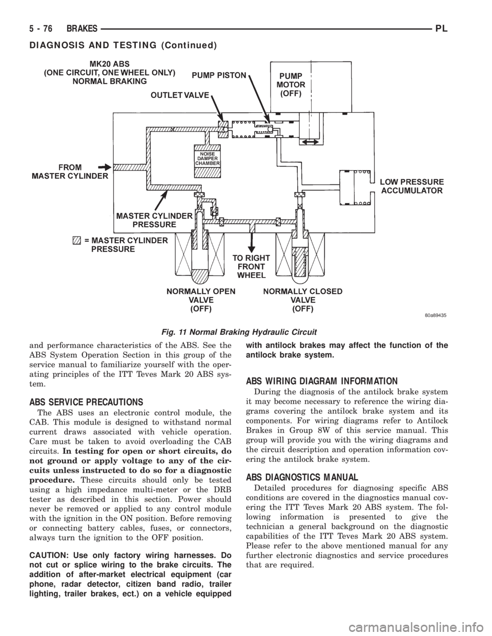
Fig. 11 Normal Braking Hydraulic Circuit
5 - 76 BRAKESPL
DIAGNOSIS AND TESTING (Continued)
Page 200 of 1200

DIAGNOSIS AND TESTING
COOLING SYSTEM DIAGNOSIS
CONDITION POSSIBLE CAUSE CORRECTION
TEMPERATURE GAUGE READS
LOW1. Has a Diagnostic Trouble Code
(DTC) been set indicating a stuck
open engine thermostat?1. Refer to On Board Diagnostic in
Group 25. Replace thermostat if
necessary. If a (DTC) has not been
set, the problem may be with the
temperature gauge.
2. Is the temperature gauge (if
equipped) connected to the
temperature gauge coolant sensor
on the engine?2. Check the connector at the
engine coolant sensor. Refer to
Group 8E. Repair as necessary.
3. Is the temperature gauge (if
equipped) operating OK?3. Check Gauge operation. Refer to
Group 8E. Repair as necessary.
4. Coolant level low during cold
ambient temperature, accompanied
by poor heater performance.4. Check coolant level in the coolant
overflow/reserve tank and the
radiator. Inspect the system for
leaks. Repair as necessary. Refer to
WARNINGS outlined in this section
before removing pressure cap.
TEMPERATURE GAUGE READS
HIGH OR ENGINE COOLANT
WARNING LAMP ILLUMINATES.
COOLANT MAY OR MAY NOT BE
LOST FROM SYSTEM.1. Trailer being towed, a steep hill
being climbed, vehicle being
operated in slow moving traffic, or
engine idling during high ambient
(outside) temperatures with air
conditioning on. High altitudes
Could aggravate these conditions.1. This may be a temporary
condition and repair is not
necessary. Turn off the air
conditioning and drive the vehicle
without any of the previous
conditions. Observe the temperature
gauge the gauge should return to
the normal range. If the gauge does
not return to the normal range,
determine the cause of the
overheating and repair. Refer to
POSSIBLE CAUSES in this section.
2. Is temperature gauge (if
equipped) reading correctly?2. Check gauge. Refer to Group 8E.
Repair as necessary.
3. Is temperature warning lamp (if
equipped) illuminating
unnecessarily?3. Check warning lamp operation.
Refer to Group 8E. Repair as
necessary.
4. Coolant low in overflow/reserve
tank and radiator?4. Check for coolant leaks and
repair as necessary. Refer to
checking cooling system for leaks in
this group.
5. Pressure cap not installed tightly.
If cap is loose, boiling point of
coolant will be lowered. Also refer
to the following step 6.5. Tighten cap.
6. Poor seals at radiator cap. 6. (a) Check condition of cap and
cap seals. Refer to Radiator cap
Inspection. Replace cap if
necessary.
6. (b) Check condition of filler neck.
If neck is bent or damaged, replace
neck.
PLCOOLING 7 - 7
Page 398 of 1200

SECTION IDENTIFICATION
The wiring diagrams are grouped into individual
sections. If a component is most likely found in a par-
ticular group, it will be shown complete (all wires,
connectors, and pins) within that group. For exam-
ple, the Auto Shutdown Relay is most likely to be
found in Group 30, so it is shown there complete. It
can, however, be shown partially in another group if
it contains some associated wiring.
SYMBOLS
International symbols are used throughout the wir-
ing diagrams. These symbols are consistent with
those being used around the world.
GROUP TOPIC
8W-01 thru 8W-09 General Information and
Diagram Overview
8W-10 thru 8W-19 Main Sources of Power and
Vehicle Grounding
8W-20 thru 8W-29 Starting and Charging
8W-30 thru 8W-39 Powertrain/Drivetrain Systems
8W-40 thru 8W-49 Body Electrical items and A/C
8W-50 thru 8W-59 Exterior Lighting, Wipers, and
Trailer Tow
8W-60 thru 8W-69 Power Accessories
8W-70 Splice Information
8W-80 Connector Pin Outs
8W-90 Connector Locations (including
grounds)
8W-95 Splice Locations
PL8W - 01 GENERAL INFORMATION 8W - 01 - 5
DESCRIPTION AND OPERATION (Continued)