1999 DODGE NEON light
[x] Cancel search: lightPage 4 of 1200
MAINTENANCE SCHEDULES
INDEX
page page
GENERAL INFORMATION
INTRODUCTION......................... 3
SCHEDULE ± A.......................... 3SCHEDULE ± B.......................... 4
UNSCHEDULED INSPECTION............... 3
GENERAL INFORMATION
INTRODUCTION
Service and maintenance procedures for compo-
nents and systems listed in Schedule ± A or B can be
found by using the Group Tab Locator index at the
front of this manual. If it is not clear which group
contains the information needed, refer to the index at
the back of this manual.
There are two maintenance schedules that show
proper service based on the conditions that the vehi-
cle is subjected to. Use the schedule that best
describes these conditions.
Schedule ±A, lists maintenance recommended for
vehicles used for general transportation.
Schedule ±B, lists maintenance recommended for
vehicles used under the following conditions:
²Frequent short trip driving less than 5 miles (8
km)
²Frequent driving in dusty conditions
²Frequent trailer towing
²Extensive idling
²More than 50% of your driving is at sustained
high speeds during hot weather, above 90ÉF (32ÉC)
Where time and mileage are listed, follow the
interval that occurs first.
EMISSION CONTROL SYSTEM MAINTENANCE
The scheduled emission maintenance listed inbold
typeon the Maintenance Schedules, must be done at
the mileage specified to assure the continued proper
functioning of the emission control system. These,
and all other maintenance services included in this
manual, should be done to provide the best vehicle
performance and reliability. More frequent mainte-
nance may be needed for vehicles in severe operating
conditions such as dusty areas and very short trip
driving.
UNSCHEDULED INSPECTION
At Each Stop For Fuel
²Check engine oil level, add as required.
²Check windshield washer solvent and add if
required.
Once A Month
²Check tire pressure and look for unusual wear
or damage.
²Inspect battery, clean, and tighten terminals as
required.
²Check fluid levels of coolant reservoir, power
steering and automatic transmission and add as
required.
²Check all lights and all other electrical items for
correct operation.
At Each Oil Change
²Inspect exhaust system.
²Inspect brake hoses.
²Inspect the CV joints and front suspension com-
ponents.
²Rotate the tires at each oil change interval
shown on Schedule ± A (7,500 miles) or every other
interval shown on schedule ± B (6,000 miles).
²Check coolant level, hoses and clamps.
²Check the manual transaxle fluid level.
²If the mileage is less than 7,500 miles (12 000
km) yearly, replace the engine oil filter at each oil
change.
SCHEDULE ± A
7,500 Miles (12 000 km) or at 6 months
²Change engine oil.
15,000 Miles (24 000 km) or at 12 months
²Change engine oil.
²Replace engine oil filter.
²Adjust drive belt tension.
22,500 Miles (36 000 km) or at 18 months
²Change engine oil.
²Inspect the front brake pads and rear brake lin-
ings.
30,000 Miles (48 000 km) or at 24 months
²Change engine oil.
²Replace engine oil filter.
²Lubricate front suspension ball joints.
²Adjust drive belt tension.
PLLUBRICATION AND MAINTENANCE 0 - 3
Page 17 of 1200
CAMBER ADJUSTMENT BOLT PACKAGE INSTALLATION
PROCEDURE
(1) If front and or rear camber readings obtained
are not within the required specification range, a
Mopar Service Kit is available to provide the
required adjustment. The kit contains new bolts and
nuts for the strut clevis bracket to steering knuckle
attachment. The bolts contained in the service kit,
are slightly undersize allowing for movement
between the strut clevis bracket and steering
knuckle. The movement allowed by the undersize
bolts will provide approximately 2 degrees of camber
adjustment per side of vehicle. To install new bolts in
service kit follow the procedure below.
CAUTION: The Mopar Service Kit for allowing
adjustment of front and rear camber are different
for the front and rear of the vehicle. When using the
service kits be sure that the front and rear strut
attaching bolts are always used in the right location
on the vehicle.
(2) Raise front and or rear of vehicle until tires are
not supporting the weight of the vehicle.
CAUTION: The steering knuckle and rear knuckle
to strut assembly attaching bolts are serrated and
must not be turned during removal. Remove nuts
while holding bolts stationary in the steering knuck-
les.
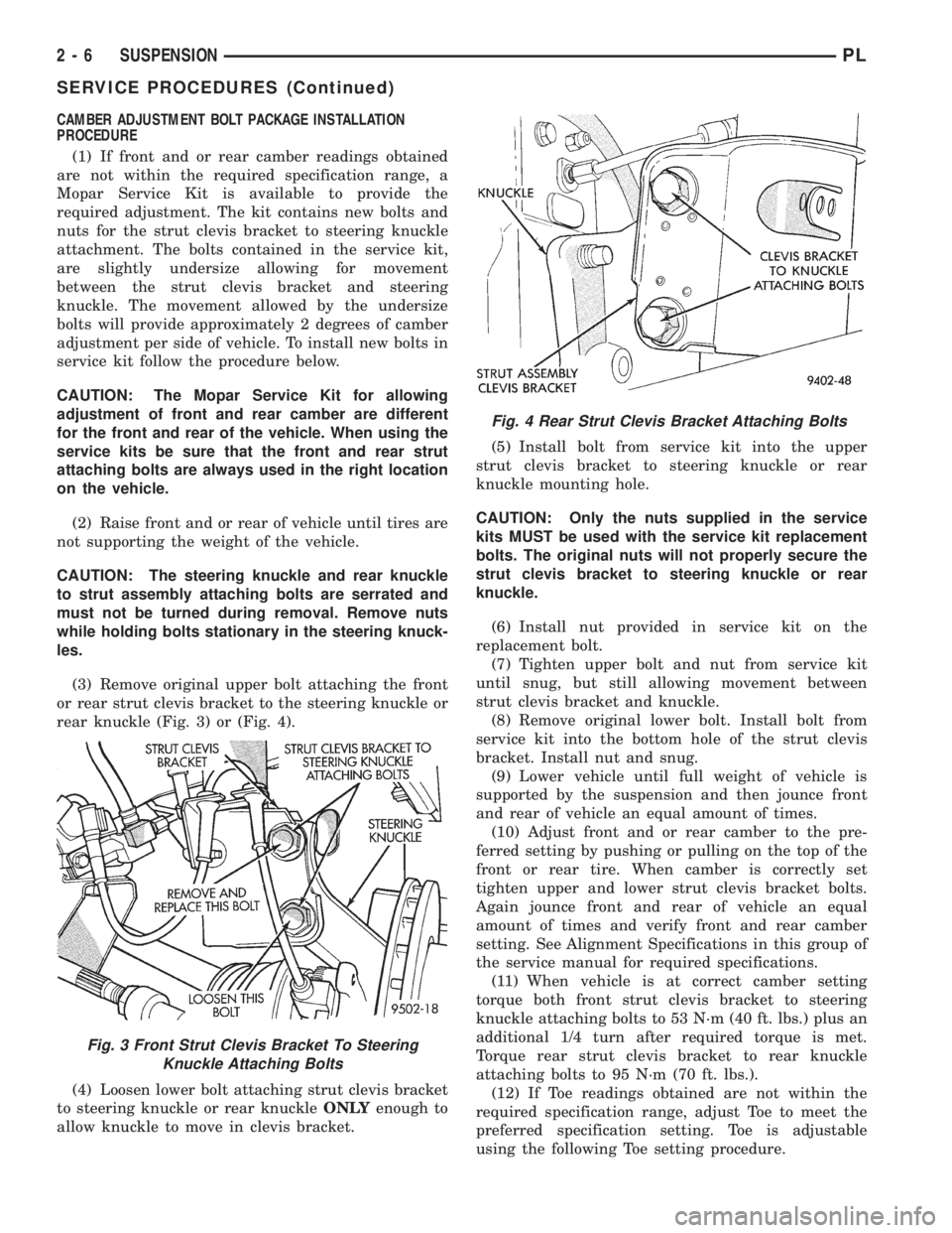
(3) Remove original upper bolt attaching the front
or rear strut clevis bracket to the steering knuckle or
rear knuckle (Fig. 3) or (Fig. 4).
(4) Loosen lower bolt attaching strut clevis bracket
to steering knuckle or rear knuckleONLYenough to
allow knuckle to move in clevis bracket.(5) Install bolt from service kit into the upper
strut clevis bracket to steering knuckle or rear
knuckle mounting hole.
CAUTION: Only the nuts supplied in the service
kits MUST be used with the service kit replacement
bolts. The original nuts will not properly secure the
strut clevis bracket to steering knuckle or rear
knuckle.
(6) Install nut provided in service kit on the
replacement bolt.
(7) Tighten upper bolt and nut from service kit
until snug, but still allowing movement between
strut clevis bracket and knuckle.
(8) Remove original lower bolt. Install bolt from
service kit into the bottom hole of the strut clevis
bracket. Install nut and snug.
(9) Lower vehicle until full weight of vehicle is
supported by the suspension and then jounce front
and rear of vehicle an equal amount of times.
(10) Adjust front and or rear camber to the pre-
ferred setting by pushing or pulling on the top of the
front or rear tire. When camber is correctly set
tighten upper and lower strut clevis bracket bolts.
Again jounce front and rear of vehicle an equal
amount of times and verify front and rear camber
setting. See Alignment Specifications in this group of
the service manual for required specifications.
(11) When vehicle is at correct camber setting
torque both front strut clevis bracket to steering
knuckle attaching bolts to 53 N´m (40 ft. lbs.) plus an
additional 1/4 turn after required torque is met.
Torque rear strut clevis bracket to rear knuckle
attaching bolts to 95 N´m (70 ft. lbs.).
(12) If Toe readings obtained are not within the
required specification range, adjust Toe to meet the
preferred specification setting. Toe is adjustable
using the following Toe setting procedure.
Fig. 3 Front Strut Clevis Bracket To Steering
Knuckle Attaching Bolts
Fig. 4 Rear Strut Clevis Bracket Attaching Bolts
2 - 6 SUSPENSIONPL
SERVICE PROCEDURES (Continued)
Page 26 of 1200
Use the procedure and special tools shown in the
service procedures section for the wheel mounting
studs when replacing the wheel attaching studs.
The hub and bearing assembly does not require
removal from the steering knuckle or the rear
knuckle to replace the wheel attaching studs in the
hub and bearing assembly.
DIAGNOSIS AND TESTING
MCPHERSON STRUT ASSEMBLY
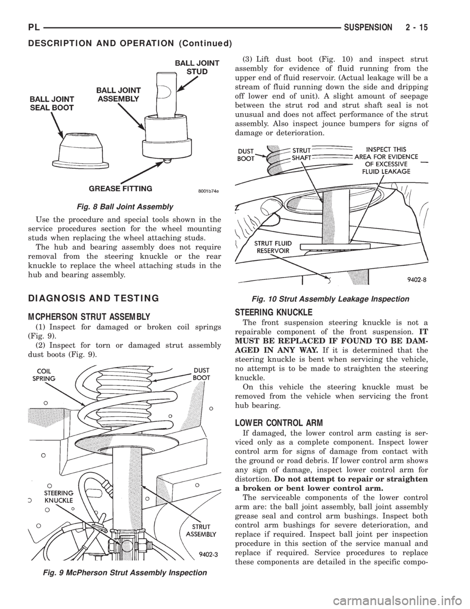
(1) Inspect for damaged or broken coil springs
(Fig. 9).
(2) Inspect for torn or damaged strut assembly
dust boots (Fig. 9).(3) Lift dust boot (Fig. 10) and inspect strut
assembly for evidence of fluid running from the
upper end of fluid reservoir. (Actual leakage will be a
stream of fluid running down the side and dripping
off lower end of unit). A slight amount of seepage
between the strut rod and strut shaft seal is not
unusual and does not affect performance of the strut
assembly. Also inspect jounce bumpers for signs of
damage or deterioration.
STEERING KNUCKLE
The front suspension steering knuckle is not a
repairable component of the front suspension.IT
MUST BE REPLACED IF FOUND TO BE DAM-
AGED IN ANY WAY.If it is determined that the
steering knuckle is bent when servicing the vehicle,
no attempt is to be made to straighten the steering
knuckle.
On this vehicle the steering knuckle must be
removed from the vehicle when servicing the front
hub bearing.
LOWER CONTROL ARM
If damaged, the lower control arm casting is ser-
viced only as a complete component. Inspect lower
control arm for signs of damage from contact with
the ground or road debris. If lower control arm shows
any sign of damage, inspect lower control arm for
distortion.Do not attempt to repair or straighten
a broken or bent lower control arm.
The serviceable components of the lower control
arm are: the ball joint assembly, ball joint assembly
grease seal and control arm bushings. Inspect both
control arm bushings for severe deterioration, and
replace if required. Inspect ball joint per inspection
procedure in this section of the service manual and
replace if required. Service procedures to replace
these components are detailed in the specific compo-
Fig. 8 Ball Joint Assembly
Fig. 9 McPherson Strut Assembly Inspection
Fig. 10 Strut Assembly Leakage Inspection
PLSUSPENSION 2 - 15
DESCRIPTION AND OPERATION (Continued)
Page 53 of 1200
a unique bolt and nut assembly at each end. The lat-
eral arm to rear crossmember attaching bolts are
longer than the lateral arm to knuckle attaching
bolts. Each lateral arm to knuckle attaching bolt and
nut assembly uses 2 flat washers. Each lateral arm
to rear crossmember attaching bolt uses 1 flat
washer and 1 adjustment cam to provide a means for
rear wheel Toe adjustment. The tension strut assem-
bly attaches to a bracket on the frame rail and to the
bottom of the knuckle.
Lateral arms, tension struts and knuckles are nor-
mally replaced only when the part has been damaged
or when the vehicle has been involved in an accident.
If a suspension part has been damaged, be sure to
check the underbody dimensions of the car. If under-
body dimensions of the vehicle are not correct, the
frame must be straightened before replacement sus-
pension components are installed.
DIAGNOSIS AND TESTING
STRUT INSPECTION (ON VEHICLE)
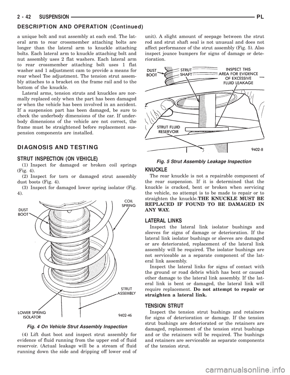
(1) Inspect for damaged or broken coil springs
(Fig. 4).
(2) Inspect for torn or damaged strut assembly
dust boots (Fig. 4).
(3) Inspect for damaged lower spring isolator (Fig.
4).
(4) Lift dust boot and inspect strut assembly for
evidence of fluid running from the upper end of fluid
reservoir. (Actual leakage will be a stream of fluid
running down the side and dripping off lower end ofunit). A slight amount of seepage between the strut
rod and strut shaft seal is not unusual and does not
affect performance of the strut assembly (Fig. 5). Also
inspect jounce bumpers for signs of damage or dete-
rioration.
KNUCKLE
The rear knuckle is not a repairable component of
the rear suspension. If it is determined that the
knuckle is cracked, bent or broken when servicing
the vehicle, no attempt is to be made to repair or to
straighten the knuckle.THE KNUCKLE MUST BE
REPLACED IF FOUND TO BE DAMAGED IN
ANY WAY.
LATERAL LINKS
Inspect the lateral link isolator bushings and
sleeves for signs of damage or deterioration. If the
lateral link isolator bushings or sleeves are damaged
or are deteriorated, replacement of the lateral link
assembly will be required. The isolator bushings are
not serviceable as a separate component of the lat-
eral link assembly.
Inspect the lateral links for signs of contact with
the ground or road debris which has bent or caused
other damage to the lateral link assembly. If the lat-
eral link is bent or damaged, the lateral link will
require replacement.Do not attempt to repair or
straighten a lateral link.
TENSION STRUT
Inspect the tension strut bushings and retainers
for signs of deterioration or damage. If the tension
strut bushings are deteriorated or the retainers are
damaged, replacement of the tension strut bushings
and or the retainers will be required. The bushings
and retainers are serviceable as separate components
of the tension strut.
Fig. 4 On Vehicle Strut Assembly Inspection
Fig. 5 Strut Assembly Leakage Inspection
2 - 42 SUSPENSIONPL
DESCRIPTION AND OPERATION (Continued)
Page 56 of 1200
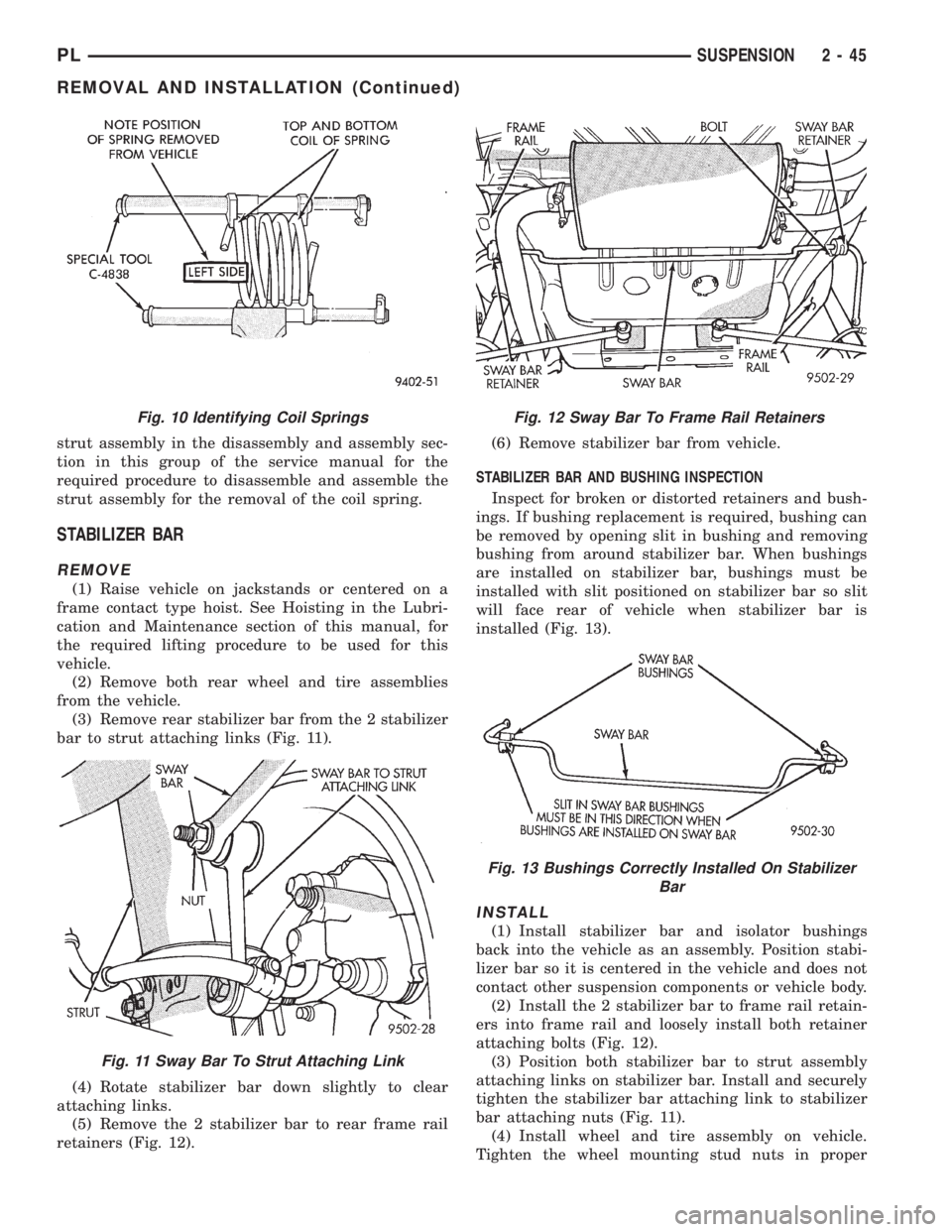
strut assembly in the disassembly and assembly sec-
tion in this group of the service manual for the
required procedure to disassemble and assemble the
strut assembly for the removal of the coil spring.
STABILIZER BAR
REMOVE
(1) Raise vehicle on jackstands or centered on a
frame contact type hoist. See Hoisting in the Lubri-
cation and Maintenance section of this manual, for
the required lifting procedure to be used for this
vehicle.
(2) Remove both rear wheel and tire assemblies
from the vehicle.
(3) Remove rear stabilizer bar from the 2 stabilizer
bar to strut attaching links (Fig. 11).
(4) Rotate stabilizer bar down slightly to clear
attaching links.
(5) Remove the 2 stabilizer bar to rear frame rail
retainers (Fig. 12).(6) Remove stabilizer bar from vehicle.
STABILIZER BAR AND BUSHING INSPECTION
Inspect for broken or distorted retainers and bush-
ings. If bushing replacement is required, bushing can
be removed by opening slit in bushing and removing
bushing from around stabilizer bar. When bushings
are installed on stabilizer bar, bushings must be
installed with slit positioned on stabilizer bar so slit
will face rear of vehicle when stabilizer bar is
installed (Fig. 13).
INSTALL
(1) Install stabilizer bar and isolator bushings
back into the vehicle as an assembly. Position stabi-
lizer bar so it is centered in the vehicle and does not
contact other suspension components or vehicle body.
(2) Install the 2 stabilizer bar to frame rail retain-
ers into frame rail and loosely install both retainer
attaching bolts (Fig. 12).
(3) Position both stabilizer bar to strut assembly
attaching links on stabilizer bar. Install and securely
tighten the stabilizer bar attaching link to stabilizer
bar attaching nuts (Fig. 11).
(4) Install wheel and tire assembly on vehicle.
Tighten the wheel mounting stud nuts in proper
Fig. 10 Identifying Coil Springs
Fig. 11 Sway Bar To Strut Attaching Link
Fig. 12 Sway Bar To Frame Rail Retainers
Fig. 13 Bushings Correctly Installed On Stabilizer
Bar
PLSUSPENSION 2 - 45
REMOVAL AND INSTALLATION (Continued)
Page 67 of 1200
the jounce and rebound travel of the front suspen-
sion.
On vehicles equipped with ABS brakes, the outer
C/V joint is equipped with a tone wheel used to
determine vehicle speed for ABS brake operation.
The inner tripod joint of both driveshafts is splined
into the transaxle side gears. The inner tripod joints
are retained in the side gears of the transaxle using
a snap ring located in the stub shaft of the tripod
joint. The outer C/V joint has a stub shaft that is
splined into the wheel hub and retained by a hub nut
using a nut lock and cotter pin.
NOTE: This vehicle does not use a rubber±lip bear-
ing seal as on previous front±wheel±drive cars to
prevent contamination of the front wheel bearing.
On these vehicles, the face of the outer C/V joint
fits deeply into the steering knuckle, using a close
outer C/V joint±to±steering knuckle fit. This design
deters direct water splash on bearing seal while
allowing any water that gets in, to run out the bot-
tom of the steering knuckle bearing bore. It is
important to thoroughly clean the outer C/V joint
and the wheel bearing area in the steering knuckle
before it is assembled after servicing.
DIAGNOSIS AND TESTING
DRIVESHAFT DIAGNOSIS
VEHICLE INSPECTION
(1) Check for grease in the vicinity of the inboard
tripod joint and outboard C/V joint; this is a sign of
inner or outer joint seal boot or seal boot clamp dam-
age.
(2) A light film of grease may appear on the right
inner tripod joint seal boot; this is considered normal
and should not require replacement of the seal boot.
The right inner tripod joint seal boot is made of sili-
cone rubber; which will allow the weeping (sweating)
of the joint lubricant to pass through it while in oper-
ation.
NOISE AND/OR VIBRATION IN TURNS
A clicking noise and/or a vibration in turns could
be caused by one of the following conditions.
(1) Damaged outer C/V or inner tripod joint seal
boot or seal boot clamps. This will result in the loss
and/or contamination of the joint grease, resulting in
inadequate lubrication of the joint.
(2) Noise may also be caused by another compo-
nent of the vehicle coming in contact with the drive-
shafts.
CLUNKING NOISE DURING ACCELERATION
This noise may be a result of one of the following
conditions:
(1) A torn seal boot on the inner or outer joint of
the driveshaft assembly.
(2) A loose or missing clamp on the inner or outer
joint of the driveshaft assembly.
(3) A damaged or worn driveshaft C/V joint.
SHUDDER OR VIBRATION DURING
ACCELERATION
(1) A worn or damaged driveshaft inner tripod
joint.
(2) A sticking tripod joint spider assembly (inner
tripod joint only).
(3) Improper wheel alignment. See Wheel Align-
ment in this group for alignment checking and set-
ting procedures and specifications.
VIBRATION AT HIGHWAY SPEEDS
(1) Foreign material (mud, etc.) packed on the
backside of the wheel(s).
(2) Out of balance front tires or wheels. See Group
22, Wheels And Tires for the required balancing pro-
cedure.
(3) Improper tire and/or wheel runout. See Group
22, Wheels And Tires for the required runout check-
ing procedure.
REMOVAL AND INSTALLATION
FRONT DRIVESHAFTS
CAUTION: Boot sealing is vital to retain special
lubricants and to prevent foreign contaminants
from entering the C/V joint. Mishandling, such as
allowing the assemblies to dangle unsupported, or
pulling or pushing the ends can cut boots or dam-
age C/V joints. During removal and installation pro-
cedures, always support both ends of the driveshaft
to prevent damage.
REMOVAL
CAUTION: The driveshaft, when installed, acts as a
bolt and secures the front hub/bearing assembly. If
vehicle is to be supported or moved on its wheels
with a driveshaft removed, install a PROPER±SIZED
BOLT AND NUT through front hub. Tighten bolt and
nut to 203 N´m (150 ft. lbs.). This will ensure that
the hub bearing cannot loosen.
(1) Remove cotter pin, nut lock, and spring washer
(Fig. 2) from the end of the outer C/V joint stub axle.
(2) Loosen (but do not remove) stub axle±to±hub/
bearing retaining nut (Fig. 3). Loosen hub nut while
3 - 2 DIFFERENTIAL AND DRIVELINEPL
GENERAL INFORMATION (Continued)
Page 70 of 1200
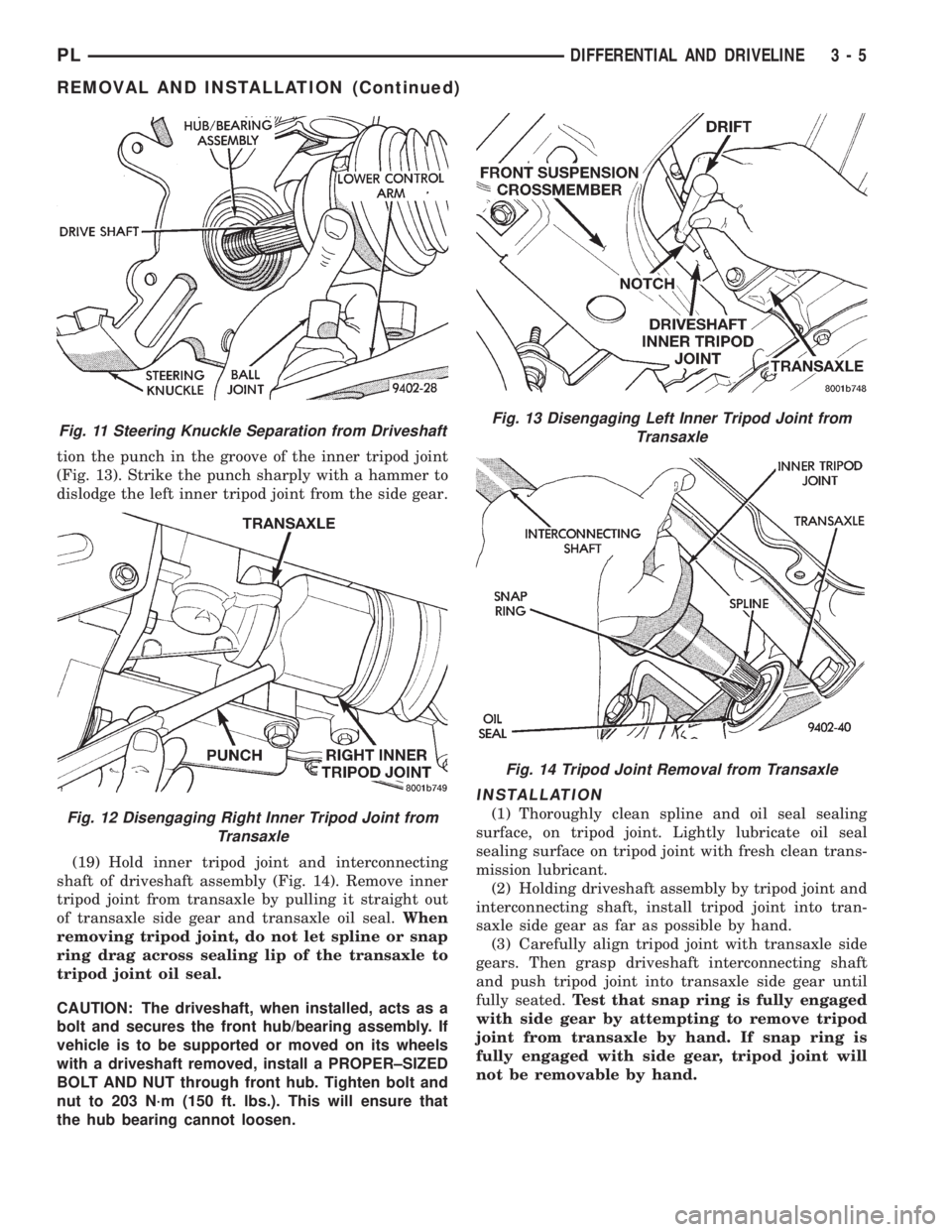
tion the punch in the groove of the inner tripod joint
(Fig. 13). Strike the punch sharply with a hammer to
dislodge the left inner tripod joint from the side gear.
(19) Hold inner tripod joint and interconnecting
shaft of driveshaft assembly (Fig. 14). Remove inner
tripod joint from transaxle by pulling it straight out
of transaxle side gear and transaxle oil seal.When
removing tripod joint, do not let spline or snap
ring drag across sealing lip of the transaxle to
tripod joint oil seal.
CAUTION: The driveshaft, when installed, acts as a
bolt and secures the front hub/bearing assembly. If
vehicle is to be supported or moved on its wheels
with a driveshaft removed, install a PROPER±SIZED
BOLT AND NUT through front hub. Tighten bolt and
nut to 203 N´m (150 ft. lbs.). This will ensure that
the hub bearing cannot loosen.
INSTALLATION
(1) Thoroughly clean spline and oil seal sealing
surface, on tripod joint. Lightly lubricate oil seal
sealing surface on tripod joint with fresh clean trans-
mission lubricant.
(2) Holding driveshaft assembly by tripod joint and
interconnecting shaft, install tripod joint into tran-
saxle side gear as far as possible by hand.
(3) Carefully align tripod joint with transaxle side
gears. Then grasp driveshaft interconnecting shaft
and push tripod joint into transaxle side gear until
fully seated.Test that snap ring is fully engaged
with side gear by attempting to remove tripod
joint from transaxle by hand. If snap ring is
fully engaged with side gear, tripod joint will
not be removable by hand.
Fig. 11 Steering Knuckle Separation from Driveshaft
Fig. 12 Disengaging Right Inner Tripod Joint from
Transaxle
Fig. 13 Disengaging Left Inner Tripod Joint from
Transaxle
Fig. 14 Tripod Joint Removal from Transaxle
PLDIFFERENTIAL AND DRIVELINE 3 - 5
REMOVAL AND INSTALLATION (Continued)
Page 82 of 1200
BRAKES
CONTENTS
page page
ANTILOCK BRAKE SYSTEM±TEVES MARK 20 . 69
BASE BRAKE SYSTEM..................... 2GENERAL INFORMATION................... 1
GENERAL INFORMATION
INDEX
page
GENERAL INFORMATION
BASE BRAKE SYSTEM DESCRIPTION........ 1
GENERAL INFORMATION
BASE BRAKE SYSTEM DESCRIPTION
Typical brake equipment consists of:
²Double pin floating caliper disc front brakes.
²Rear automatic adjusting drum brakes.
²Brake Fluid Level Switch.
²Master cylinder.
²Vacuum power booster.
²Double pin floating caliper rear disc brakes are
available on some models.
²Hand operated auto adjust park brake lever.
²Front disc brake pads are semi-metallic.
Vehicles equipped with the optional antilock brake
system (ABS) use a system designated Mark 20 and
is supplied by Teves. This system shares the base
brake hardware with vehicles not equipped withABS. A vehicle equipped with ABS does however use
a different vacuum booster, master cylinder and
brake tubes. Also included in the ABS system is an
integrated control unit (ICU), four wheel speed sen-
sors, and an electronic controller referred to as the
controller antilock brakes (CAB). These components
will be described in detail in the Teves Mark 20 ABS
brake section in this group of the service manual.
The hydraulic brake system is diagonally split on
both the Non-ABS and ABS braking system. With the
left front and right rear brakes on one hydraulic sys-
tem and the right front and left rear on the other.
The master cylinder is anodized, lightweight alu-
minum. On vehicles equipped with front disc brakes
and rear drum brakes, the master cylinder bore is
21.0 mm. On vehicles equipped with four wheel disc
brakes, the master cylinder bore is 22.2 mm.
PLBRAKES 5 - 1