1999 DODGE NEON child lock
[x] Cancel search: child lockPage 366 of 1200

Instrument Panel and Systems for removal proce-
dures.
(2) Turn the ignition switch ON.
(3) Using a voltmeter, check for battery voltage at
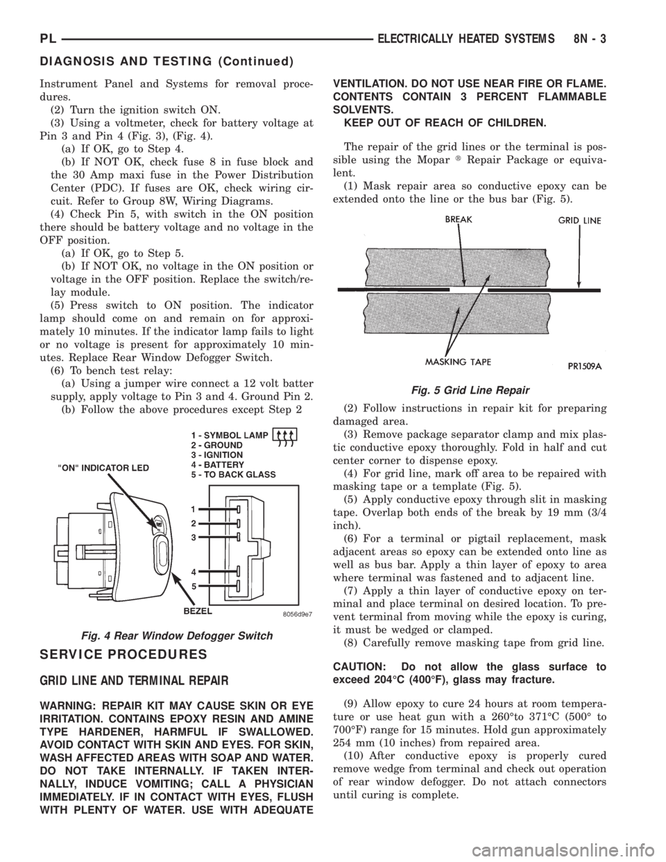
Pin 3 and Pin 4 (Fig. 3), (Fig. 4).
(a) If OK, go to Step 4.
(b) If NOT OK, check fuse 8 in fuse block and
the 30 Amp maxi fuse in the Power Distribution
Center (PDC). If fuses are OK, check wiring cir-
cuit. Refer to Group 8W, Wiring Diagrams.
(4) Check Pin 5, with switch in the ON position
there should be battery voltage and no voltage in the
OFF position.
(a) If OK, go to Step 5.
(b) If NOT OK, no voltage in the ON position or
voltage in the OFF position. Replace the switch/re-
lay module.
(5) Press switch to ON position. The indicator
lamp should come on and remain on for approxi-
mately 10 minutes. If the indicator lamp fails to light
or no voltage is present for approximately 10 min-
utes. Replace Rear Window Defogger Switch.
(6) To bench test relay:
(a) Using a jumper wire connect a 12 volt batter
supply, apply voltage to Pin 3 and 4. Ground Pin 2.
(b) Follow the above procedures except Step 2
SERVICE PROCEDURES
GRID LINE AND TERMINAL REPAIR
WARNING: REPAIR KIT MAY CAUSE SKIN OR EYE
IRRITATION. CONTAINS EPOXY RESIN AND AMINE
TYPE HARDENER, HARMFUL IF SWALLOWED.
AVOID CONTACT WITH SKIN AND EYES. FOR SKIN,
WASH AFFECTED AREAS WITH SOAP AND WATER.
DO NOT TAKE INTERNALLY. IF TAKEN INTER-
NALLY, INDUCE VOMITING; CALL A PHYSICIAN
IMMEDIATELY. IF IN CONTACT WITH EYES, FLUSH
WITH PLENTY OF WATER. USE WITH ADEQUATEVENTILATION. DO NOT USE NEAR FIRE OR FLAME.
CONTENTS CONTAIN 3 PERCENT FLAMMABLE
SOLVENTS.
KEEP OUT OF REACH OF CHILDREN.
The repair of the grid lines or the terminal is pos-
sible using the MopartRepair Package or equiva-
lent.
(1) Mask repair area so conductive epoxy can be
extended onto the line or the bus bar (Fig. 5).
(2) Follow instructions in repair kit for preparing
damaged area.
(3) Remove package separator clamp and mix plas-
tic conductive epoxy thoroughly. Fold in half and cut
center corner to dispense epoxy.
(4) For grid line, mark off area to be repaired with
masking tape or a template (Fig. 5).
(5) Apply conductive epoxy through slit in masking
tape. Overlap both ends of the break by 19 mm (3/4
inch).
(6) For a terminal or pigtail replacement, mask
adjacent areas so epoxy can be extended onto line as
well as bus bar. Apply a thin layer of epoxy to area
where terminal was fastened and to adjacent line.
(7) Apply a thin layer of conductive epoxy on ter-
minal and place terminal on desired location. To pre-
vent terminal from moving while the epoxy is curing,
it must be wedged or clamped.
(8) Carefully remove masking tape from grid line.
CAUTION: Do not allow the glass surface to
exceed 204ÉC (400ÉF), glass may fracture.
(9) Allow epoxy to cure 24 hours at room tempera-
ture or use heat gun with a 260Éto 371ÉC (500É to
700ÉF) range for 15 minutes. Hold gun approximately
254 mm (10 inches) from repaired area.
(10) After conductive epoxy is properly cured
remove wedge from terminal and check out operation
of rear window defogger. Do not attach connectors
until curing is complete.
Fig. 4 Rear Window Defogger Switch
Fig. 5 Grid Line Repair
PLELECTRICALLY HEATED SYSTEMS 8N - 3
DIAGNOSIS AND TESTING (Continued)
Page 370 of 1200

POWER DOOR LOCKS
CONTENTS
page page
POWER DOOR LOCKS..................... 1REMOTE KEYLESS ENTRY.................. 3
POWER DOOR LOCKS
INDEX
page page
DESCRIPTION AND OPERATION
INTRODUCTION......................... 1
DIAGNOSIS AND TESTING
DOOR LOCK MOTOR..................... 1
DOOR LOCK SWITCH..................... 1WIRING................................ 1
REMOVAL AND INSTALLATION
DOOR LOCK MOTOR..................... 2
DOOR LOCK SWITCH..................... 2
DESCRIPTION AND OPERATION
INTRODUCTION
All doors can be locked or unlocked electrically by
operating the switch on either front door panels.
The rear doors can be locked or unlocked by actu-
ation of the front door switch, or can be locked or
unlocked mechanically and independently with their
respective locking knobs.
The front doors can be locked or unlocked mechan-
ically with the locking knob regardless of electrical
locking and unlocking actuation with the front door
knobs.
The right and left front door can be locked or
unlocked mechanically from the outside with the key
or electrically as described above.
CHILD PROTECTION LOCK
The child protection lock is on the rear door only.
The lock will disable the inside door handle from
opening the door when engaged. The lock is part of
the latch/lock assembly. The lock is engaged by mov-
ing a lever that is located on the rearward inside
edge of the door.
DIAGNOSIS AND TESTING
DOOR LOCK MOTOR
Make certain battery is in normal condition before
circuits are tested.To determine which motor is faulty, check each
individual door for electrical lock and unlock or dis-
connect the motor connectors one at a time, while
operating the door lock switch. In the event that
none of the motors work, the problem maybe caused
by a shorted motor, or a bad switch. Disconnecting
the defective motor will allow the others to work.
To test an individual door lock motor, disconnect
the electrical connector from the motor. To lock the
door, connect a 12 volt power source to the positive
pin of the lock motor and a ground wire to the other
pin (Fig. 1) To unlock the door reverse the wire con-
nections at the motor pin terminals. If these results
are NOT obtained, replace the door latch assembly.
DOOR LOCK SWITCH
Remove the switch from its mounting location.
Using an ohmmeter, refer to (Fig. 2) to determine if
continuity is correct in the Lock and Unlock switch
positions. If these results are not obtained, replace
the switch.
WIRING
The following wiring test sequence determines
whether or not voltage is continuous through the
body harness to switch.
(1) Remove left side switch from door trim panel.
(2) Carefully separate multiple terminal block on
wiring harness from switch body.
PLPOWER DOOR LOCKS 8P - 1
Page 1083 of 1200

BODY COMPONENTS
INDEX
page page
DIAGNOSIS AND TESTING
WATER LEAKS.......................... 3
WIND NOISE............................ 4
SERVICE PROCEDURES
HEAT STAKING.......................... 4
REMOVAL AND INSTALLATION
WINDOW REGULATORÐ4 DOOR........... 36
A-PILLAR TRIM.......................... 4
B-PILLAR APPLIQUEÐ2 DOOR.............. 5
B-PILLAR APPLIQUEÐ4 DOOR.............. 5
B-PILLAR TRIMÐ4 DOOR.................. 6
B-PILLAR WEATHERSTRIP CHANNEL......... 6
BODY VENT............................. 6
CARPET............................... 7
CHILD RESTRAINT SEAT BACK............. 8
CHILD SEAT MODULE..................... 8
COWL COVER........................... 7
DOOR HINGE........................... 9
DOOR LOCK CYLINDER.................. 10
DOOR OPENING TRIM WELT.............. 10
DOOR SILL TRIM........................ 10
DOOR................................. 9
FLOOR CONSOLE LATCH................. 11
FLOOR CONSOLE....................... 11
FRONT DOOR CHECK STOP............... 11
FRONT DOOR GLASSÐ2 DOOR............ 12
FRONT DOOR GLASSÐ4 DOOR............ 13
FRONT DOOR INNER BELT WEATHERSTRIP . . 13
FRONT DOOR LATCH STRIKER............ 14
FRONT DOOR LATCH.................... 13
FRONT DOOR OUTER BELT WEATHERSTRIP . 14
FRONT DOOR OUTSIDE HANDLE........... 14
FRONT DOOR TRIM PANEL................ 14
FRONT DOOR WATER SHIELD............. 16
FRONT DOOR WEATHERSTRIP............ 16
FRONT OUTBOARD SEAT BELT............ 17
FRONT SEAT BELT BUCKLE............... 18
FRONT SEAT BELT RETRACTOR........... 18
FRONT SEAT........................... 17
FRONT SHOULDER BELT ADJUSTER........ 18
FRONT VERTICAL GUIDE BAR............. 18
GRILLE............................... 19
HEADLINING........................... 19
HOOD HINGE.......................... 20
HOOD LATCH.......................... 21
HOOD RELEASE CABLE.................. 21
HOOD................................ 20
LOCK BUTTON BELL-CRANK.............. 21
LOWER QUARTER TRIMÐ4 DOOR.......... 22PARCEL SHELF TRIM.................... 22
QUARTER TRIM PANELÐ2 DOOR........... 22
REAR DOOR GLASS..................... 23
REAR DOOR INNER BELT WEATHERSTRIP . . . 23
REAR DOOR INTERLOCK LATCH STRIKER . . . 24
REAR DOOR LATCH STRIKER............. 24
REAR DOOR LATCH..................... 24
REAR DOOR LOCK BELL CRANK........... 24
REAR DOOR OUTER BELT WEATHERSTRIP . . 25
REAR DOOR TRIM....................... 25
REAR DOOR WINDOW REGULATOR........ 25
REAR SEAT BACK....................... 26
REAR SEAT BELT BUCKLE................ 26
REAR SEAT BELT RETRACTOR............ 26
REAR SEAT CUSHION.................... 26
REAR SPOILER......................... 27
REAR VERTICAL GUIDE BAR.............. 27
ROOF APERTURE (RAP) MOLDING.......... 28
ROOF RACK CROSS RAILS............... 28
ROOF RACK........................... 28
ROOF RAIL WEATHER-STRIP FOUR DOOR . . . 29
ROOF RAIL WEATHER-STRIP ± TWO DOOR . . . 29
SIDE COWL TRIM....................... 30
SIDE VIEW MIRROR STANCHION........... 31
SIDE VIEW MIRROR TRIM COVER.......... 31
SIDE VIEW MIRROR..................... 30
SUN VISOR SUPPORT................... 31
SUN VISOR............................ 31
TRUNK CARPET........................ 31
TRUNK LATCH STRIKER.................. 32
TRUNK LATCH.......................... 32
TRUNK LID LIFT SPRINGS................ 33
TRUNK LID............................ 32
TRUNK LOCK CYLINDER................. 33
TRUNK TRIM PANEL..................... 34
TRUNK WEATHERSTRIP.................. 34
UPPER QUARTER TRIMÐ4 DOOR.......... 34
WINDOW INNERBELT STABILIZER.......... 34
WINDOW REGULATORÐ2 DOOR........... 35
ADJUSTMENTS
FRONT DOOR GLASS ADJUSTMENT........ 37
FRONT DOOR LATCH ADJUSTMENT........ 38
REAR DOOR GLASS ADJUSTMENT......... 38
REAR DOOR LATCH ADJUSTMENT.......... 39
SPECIFICATIONS
BODY LUBRICATION SPECIFICATIONS....... 39
SPECIAL TOOLS
BODY................................. 40
23 - 2 BODYPL