1999 DODGE NEON catalytic converter
[x] Cancel search: catalytic converterPage 256 of 1200
train Control Module (PCM) with an input signal
(voltage). The signal represents throttle blade posi-
tion. As the position of the throttle blade changes,
the resistance of the TPS changes.
The PCM supplies approximately 5 volts to the
TPS. The TPS output voltage (input signal to the
powertrain control module) represents throttle blade
position. The TPS output voltage to the PCM varies
from approximately 0.38 volts to 1.2 volts at mini-
mum throttle opening (idle) to a maximum of 3.1
volts to 4.4 volts at wide open throttle.
Along with inputs from other sensors, the PCM
uses the TPS input to determine current engine oper-
ating conditions. The PCM also adjusts fuel injector
pulse width and ignition timing based on these
inputs.
IGNITION SWITCH
In the RUN position, the ignition switch connects
power from the Power Distribution Center (PDC) to a
30 amp fuse in the fuse block, back to a bus bar in
the PDC. The bus bar feeds circuits for the Power-
train Control Module (PCM), duty cycle purge sole-
noid, EGR solenoid, and ABS system. The bus bar in
the PDC feeds the coil side of the radiator fan relay,
A/C compressor clutch relay, and the fuel pump relay.
It also feeds the Airbag Control Module (ACM)
LOCK KEY CYLINDER
The lock cylinder is inserted in the end of the
housing opposite the ignition switch. The ignition key
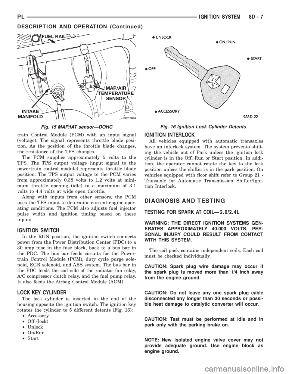
rotates the cylinder to 5 different detents (Fig. 16):
²Accessory
²Off (lock)
²Unlock
²On/Run
²Start
IGNITION INTERLOCK
All vehicles equipped with automatic transaxles
have an interlock system. The system prevents shift-
ing the vehicle out of Park unless the ignition lock
cylinder is in the Off, Run or Start position. In addi-
tion, the operator cannot rotate the key to the lock
position unless the shifter is in the park position. On
vehicles equipped with floor shift refer to Group 21 -
Transaxle for Automatic Transmission Shifter/Igni-
tion Interlock.
DIAGNOSIS AND TESTING
TESTING FOR SPARK AT COILÐ2.0/2.4L
WARNING: THE DIRECT IGNITION SYSTEMS GEN-
ERATES APPROXIMATELY 40,000 VOLTS. PER-
SONAL INJURY COULD RESULT FROM CONTACT
WITH THIS SYSTEM.
The coil pack contains independent coils. Each coil
must be checked individually.
CAUTION: Spark plug wire damage may occur if
the spark plug is moved more than 1/4 inch away
from the engine ground.
CAUTION: Do not leave any one spark plug cable
disconnected any longer than 30 seconds or possi-
ble heat damage to catalytic converter will occur.
CAUTION: Test must be performed at idle and in
park only with the parking brake on.
NOTE: New isolated engine valve cover may not
provide adequate ground. Use engine block as
engine ground.
Fig. 15 MAP/IAT sensorÐDOHCFig. 16 Ignition Lock Cylinder Detents
PLIGNITION SYSTEM 8D - 7
DESCRIPTION AND OPERATION (Continued)
Page 257 of 1200
Use a new spark plug and spark plug cable
for the following test.
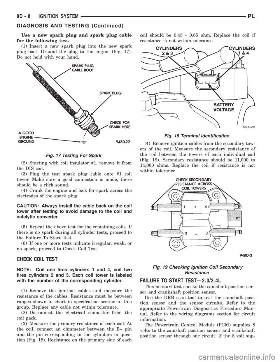
(1) Insert a new spark plug into the new spark
plug boot. Ground the plug to the engine (Fig. 17).
Do not hold with your hand.
(2) Starting with coil insulator #1, remove it from
the DIS coil.
(3) Plug the test spark plug cable onto #1 coil
tower. Make sure a good connection is made; there
should be a click sound.
(4) Crank the engine and look for spark across the
electrodes of the spark plug.
CAUTION: Always install the cable back on the coil
tower after testing to avoid damage to the coil and
catalytic converter.
(5) Repeat the above test for the remaining coils. If
there is no spark during all cylinder tests, proceed to
the Failure To Start Test.
(6) If one or more tests indicate irregular, weak, or
no spark, proceed to Check Coil Test.
CHECK COIL TEST
NOTE: Coil one fires cylinders 1 and 4, coil two
fires cylinders 2 and 3. Each coil tower is labeled
with the number of the corresponding cylinder.
(1) Remove the ignition cables and measure the
resistance of the cables. Resistance must be between
ranges shown in chart in specifcation section in this
group. Replace any cable not within tolerance.
(2) Disconnect the electrical connector from the
coil pack.
(3) Measure the primary resistance of each coil. At
the coil, connect an ohmmeter between the B+ pin
and the pin corresponding to the cylinders in ques-
tion (Fig. 18). Resistance on the primary side of eachcoil should be 0.45 - 0.65 ohm. Replace the coil if
resistance is not within tolerance.
(4) Remove ignition cables from the secondary tow-
ers of the coil. Measure the secondary resistance of
the coil between the towers of each individual coil
(Fig. 19). Secondary resistance should be 11,000 to
14,000 ohms. Replace the coil if resistance is not
within tolerance.
FAILURE TO START TESTÐ2.0/2.4L
This no-start test checks the camshaft position sen-
sor and crankshaft position sensor.
Use the DRB scan tool to test the camshaft posi-
tion sensor and the sensor circuits. Refer to the
appropriate Powertrain Diagnostics Procedure Man-
ual. Refer to the wiring diagrams section for circuit
information.
The Powertrain Control Module (PCM) supplies 8
volts to the camshaft position sensor and crankshaft
position sensor through one circuit. If the 8 volt sup-
Fig. 17 Testing For Spark
Fig. 18 Terminal Identification
Fig. 19 Checking Ignition Coil Secondary
Resistance
8D - 8 IGNITION SYSTEMPL
DIAGNOSIS AND TESTING (Continued)
Page 676 of 1200
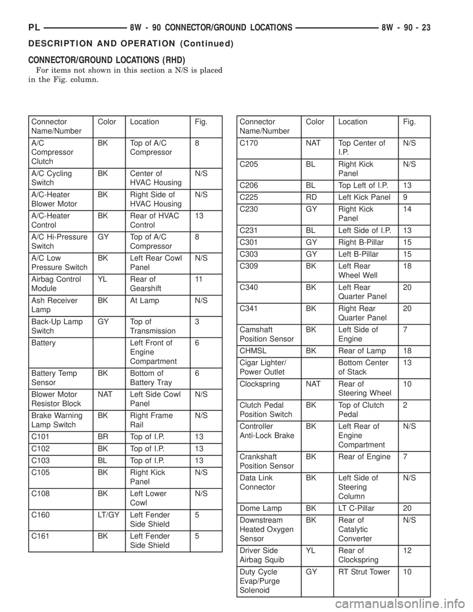
CONNECTOR/GROUND LOCATIONS (RHD)
For items not shown in this section a N/S is placed
in the Fig. column.
Connector
Name/NumberColor Location Fig.
A/C
Compressor
ClutchBK Top of A/C
Compressor8
A/C Cycling
SwitchBK Center of
HVAC HousingN/S
A/C-Heater
Blower MotorBK Right Side of
HVAC HousingN/S
A/C-Heater
ControlBK Rear of HVAC
Control13
A/C Hi-Pressure
SwitchGY Top of A/C
Compressor8
A/C Low
Pressure SwitchBK Left Rear Cowl
PanelN/S
Airbag Control
ModuleYL Rear of
Gearshift11
Ash Receiver
LampBK At Lamp N/S
Back-Up Lamp
SwitchGY Top of
Transmission3
Battery Left Front of
Engine
Compartment6
Battery Temp
SensorBK Bottom of
Battery Tray6
Blower Motor
Resistor BlockNAT Left Side Cowl
PanelN/S
Brake Warning
Lamp SwitchBK Right Frame
RailN/S
C101 BR Top of I.P. 13
C102 BK Top of I.P. 13
C103 BL Top of I.P. 13
C105 BK Right Kick
PanelN/S
C108 BK Left Lower
CowlN/S
C160 LT/GY Left Fender
Side Shield5
C161 BK Left Fender
Side Shield5Connector
Name/NumberColor Location Fig.
C170 NAT Top Center of
I.P.N/S
C205 BL Right Kick
PanelN/S
C206 BL Top Left of I.P. 13
C225 RD Left Kick Panel 9
C230 GY Right Kick
Panel14
C231 BL Left Side of I.P. 13
C301 GY Right B-Pillar 15
C303 GY Left B-Pillar 15
C309 BK Left Rear
Wheel Well18
C340 BK Left Rear
Quarter Panel20
C341 BK Right Rear
Quarter Panel20
Camshaft
Position SensorBK Left Side of
Engine7
CHMSL BK Rear of Lamp 18
Cigar Lighter/
Power OutletBottom Center
of Stack13
Clockspring NAT Rear of
Steering Wheel10
Clutch Pedal
Position SwitchBK Top of Clutch
Pedal2
Controller
Anti-Lock BrakeBK Left Rear of
Engine
CompartmentN/S
Crankshaft
Position SensorBK Rear of Engine 7
Data Link
ConnectorBK Left Side of
Steering
ColumnN/S
Dome Lamp BK LT C-Pillar 20
Downstream
Heated Oxygen
SensorBK Rear of
Catalytic
ConverterN/S
Driver Side
Airbag SquibYL Rear of
Clockspring12
Duty Cycle
Evap/Purge
SolenoidGY RT Strut Tower 10
PL8W - 90 CONNECTOR/GROUND LOCATIONS 8W - 90 - 23
DESCRIPTION AND OPERATION (Continued)
Page 816 of 1200
EXHAUST SYSTEM AND INTAKE MANIFOLD
CONTENTS
page page
GENERAL INFORMATION
CATALYTIC CONVERTER................... 4
EXHAUST BALL JOINT COUPLING.......... 1
EXHAUST FLEX-JOINT COUPLING (LEV)...... 2
EXHAUST GAS RECIRCULATION (EGR)
SYSTEM.............................. 3
EXHAUST SYSTEMS...................... 1
HEAT SHIELDS.......................... 3
DESCRIPTION AND OPERATION
EXHAUST MANIFOLD..................... 3
INTAKE MANIFOLD DOHC................. 3
INTAKE MANIFOLD SOHC................. 3
DIAGNOSIS AND TESTING
EXHAUST SYSTEM DIAGNOSIS CHART...... 4REMOVAL AND INSTALLATION
EXHAUST MANIFOLD.................... 11
EXHAUST PIPE AND MUFFLER............. 4
INTAKE MANIFOLDÐDOHC ENGINE......... 9
INTAKE MANIFOLDÐSOHC ENGINE......... 6
CLEANING AND INSPECTION
EXHAUST MANIFOLD.................... 12
INTAKE MANIFOLD DOHC................ 12
INTAKE MANIFOLD SOHC................ 12
SPECIFICATIONS
TORQUE CHART........................ 12
GENERAL INFORMATION
EXHAUST SYSTEMS
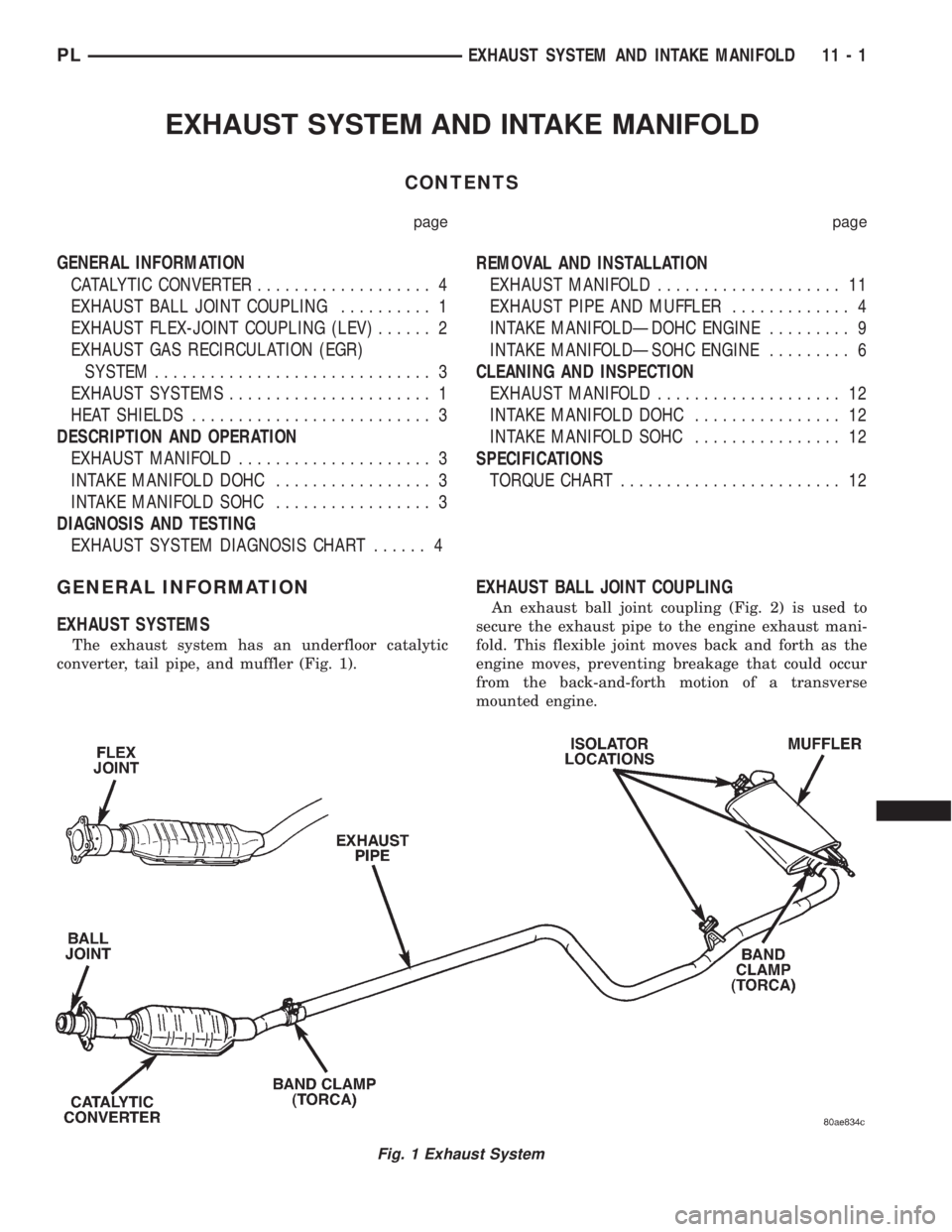
The exhaust system has an underfloor catalytic
converter, tail pipe, and muffler (Fig. 1).
EXHAUST BALL JOINT COUPLING
An exhaust ball joint coupling (Fig. 2) is used to
secure the exhaust pipe to the engine exhaust mani-
fold. This flexible joint moves back and forth as the
engine moves, preventing breakage that could occur
from the back-and-forth motion of a transverse
mounted engine.
Fig. 1 Exhaust System
PLEXHAUST SYSTEM AND INTAKE MANIFOLD 11 - 1
Page 817 of 1200

The exhaust ball joint consists of two bolts, two
springs, and a ball joint seal ring, which is a sepa-
rate part from the exhaust pipe.
EXHAUST FLEX-JOINT COUPLING (LEV)
An exhaust flex-joint coupling is used on Low
Emission Vehicles (LEV) (Fig. 3). This coupling is
used to secure the catalytic converter to the exhaust
manifold. This coupling actually moves back and
forth as the engine moves, preventing breakage that
could occur from the back and forth motion of a
transverse mounted engine.
The exhaust flex-joint is welded to the catalytic
converter.
CATALYTIC CONVERTER
There is no regularly scheduled maintenance on
any Chrysler catalytic converter (Fig. 4). If damaged,
the converter must be replaced.
CAUTION: Due to exterior physical similarities of
some catalytic converters with pipe assemblies,
extreme care should be taken with replacement
parts.
The combustion reaction caused by the catalyst
releases additional heat in the exhaust system. Caus-
ing temperature increases in the area of the reactor
under severe operating conditions. Such conditions
can exist when the engine misfires or otherwise does
not operate at peak efficiency.Do notremove spark
plug wires from plugs or by any other means short
out cylinders if exhaust system is equipped with a
catalytic converter. Failure of the catalytic converter
can occur due to temperature increases caused by
unburned fuel passing through the converter.
The use of the catalysts also involves some non-au-
tomotive problems. Unleaded gasoline must be used
to avoid poisoning the catalyst core. Do not allow
engine to operate above 1200 RPM in neutral for
extended periods over 5 minutes. This condition may
result in excessive exhaust system/floor pan temper-
atures because of no air movement under the vehicle.
Fig. 2 Ball Joint Connection
Fig. 3 Flex-Joint (LEV)
Fig. 4 Exhaust System ComponentsÐTypical
11 - 2 EXHAUST SYSTEM AND INTAKE MANIFOLDPL
GENERAL INFORMATION (Continued)
Page 819 of 1200
DIAGNOSIS AND TESTING
REMOVAL AND INSTALLATION
EXHAUST PIPE AND MUFFLER
REMOVAL
(1) Raise vehicle on hoist and apply penetrating oil
to band clamp fastener of component being removed
(Fig. 6).NOTE: Do not use petroleum-based lubricants
when removing/installing muffler or exhaust pipe
isolators as it may compromise the life of the part.
A suitable substitute is a mixture of liquid dish
soap and water.
(2) Loosen band clamp and remove support insula-
tors at muffler (Fig. 7). Remove muffler from exhaust
pipe.
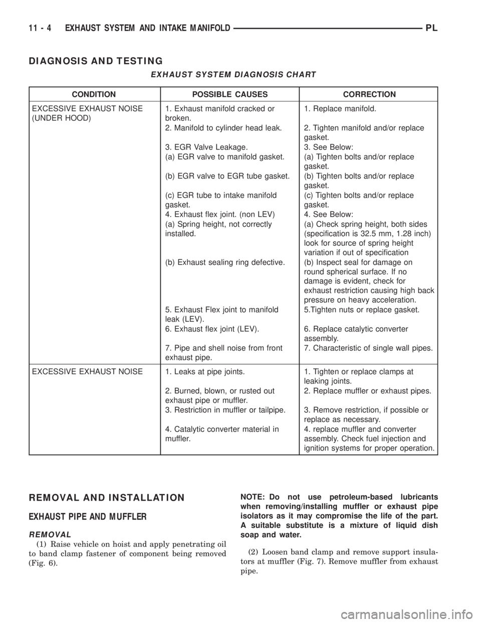
EXHAUST SYSTEM DIAGNOSIS CHART
CONDITION POSSIBLE CAUSES CORRECTION
EXCESSIVE EXHAUST NOISE
(UNDER HOOD)1. Exhaust manifold cracked or
broken.1. Replace manifold.
2. Manifold to cylinder head leak. 2. Tighten manifold and/or replace
gasket.
3. EGR Valve Leakage. 3. See Below:
(a) EGR valve to manifold gasket. (a) Tighten bolts and/or replace
gasket.
(b) EGR valve to EGR tube gasket. (b) Tighten bolts and/or replace
gasket.
(c) EGR tube to intake manifold
gasket.(c) Tighten bolts and/or replace
gasket.
4. Exhaust flex joint. (non LEV) 4. See Below:
(a) Spring height, not correctly
installed.(a) Check spring height, both sides
(specification is 32.5 mm, 1.28 inch)
look for source of spring height
variation if out of specification
(b) Exhaust sealing ring defective. (b) Inspect seal for damage on
round spherical surface. If no
damage is evident, check for
exhaust restriction causing high back
pressure on heavy acceleration.
5. Exhaust Flex joint to manifold
leak (LEV).5.Tighten nuts or replace gasket.
6. Exhaust flex joint (LEV). 6. Replace catalytic converter
assembly.
7. Pipe and shell noise from front
exhaust pipe.7. Characteristic of single wall pipes.
EXCESSIVE EXHAUST NOISE 1. Leaks at pipe joints. 1. Tighten or replace clamps at
leaking joints.
2. Burned, blown, or rusted out
exhaust pipe or muffler.2. Replace muffler or exhaust pipes.
3. Restriction in muffler or tailpipe. 3. Remove restriction, if possible or
replace as necessary.
4. Catalytic converter material in
muffler.4. replace muffler and converter
assembly. Check fuel injection and
ignition systems for proper operation.
11 - 4 EXHAUST SYSTEM AND INTAKE MANIFOLDPL
Page 820 of 1200
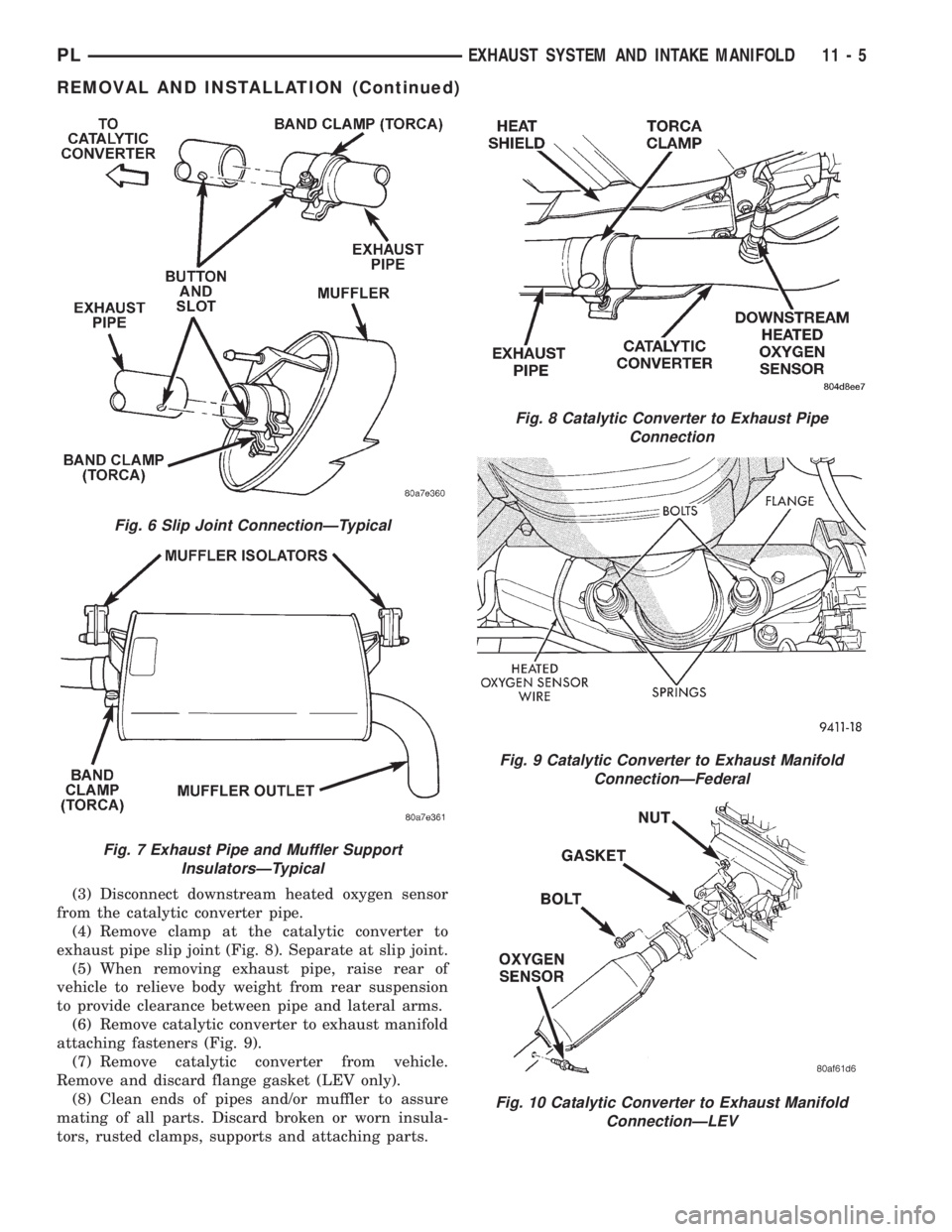
(3) Disconnect downstream heated oxygen sensor
from the catalytic converter pipe.
(4) Remove clamp at the catalytic converter to
exhaust pipe slip joint (Fig. 8). Separate at slip joint.
(5) When removing exhaust pipe, raise rear of
vehicle to relieve body weight from rear suspension
to provide clearance between pipe and lateral arms.
(6) Remove catalytic converter to exhaust manifold
attaching fasteners (Fig. 9).
(7) Remove catalytic converter from vehicle.
Remove and discard flange gasket (LEV only).
(8) Clean ends of pipes and/or muffler to assure
mating of all parts. Discard broken or worn insula-
tors, rusted clamps, supports and attaching parts.
Fig. 6 Slip Joint ConnectionÐTypical
Fig. 7 Exhaust Pipe and Muffler Support
InsulatorsÐTypical
Fig. 8 Catalytic Converter to Exhaust Pipe
Connection
Fig. 9 Catalytic Converter to Exhaust Manifold
ConnectionÐFederal
Fig. 10 Catalytic Converter to Exhaust Manifold
ConnectionÐLEV
PLEXHAUST SYSTEM AND INTAKE MANIFOLD 11 - 5
REMOVAL AND INSTALLATION (Continued)
Page 869 of 1200
deterioration, the fuel injection system uses two
heated oxygen sensors. One sensor upstream of the
catalytic convertor, one downstream of the convertor.
The PCM compares the reading from the sensors to
calculate the catalytic convertor oxygen storage
capacity and converter efficiency. Also, the PCM uses
the upstream heated oxygen sensor input when
adjusting injector pulse width.
When the catalytic converter efficiency drops below
emission standards, the PCM stores a diagnostic
trouble code and illuminates the malfunction indica-
tor lamp (MIL).
The O2S sensors produce voltages from 0 to 1 volt,
depending upon the oxygen content of the exhaust
gas in the exhaust manifold. When a large amount of
oxygen is present (caused by a lean air/fuel mixture),
the sensors produces a low voltage. When there is a
lesser amount present (rich air/fuel mixture) it pro-
duces a higher voltage. By monitoring the oxygen
content and converting it to electrical voltage, the
sensors act as a rich- lean switch.
The oxygen sensors are equipped with a heating
element that keeps the sensors at proper operating
temperature during all operating modes. Maintaining
correct sensor temperature at all times allows the
system to enter into closed loop operation sooner.
Also, it allows the system to remain in closed loop
operation during periods of extended idle.
In Closed Loop operation the PCM monitors the
O2S sensor input (along with other inputs) and
adjusts the injector pulse width accordingly. During
Open Loop operation the PCM ignores the O2 sensor
input. The PCM adjusts injector pulse width based
on preprogrammed (fixed) values and inputs from
other sensors.
The Automatic Shutdown (ASD) relay supplies bat-
tery voltage to both the upstream and downstream
heated oxygen sensors. The oxygen sensors are
equipped with a heating element. The heating ele-
ments reduce the time required for the sensors to
reach operating temperature.
UPSTREAM OXYGEN SENSOR
The input from the upstream heated oxygen sensor
tells the PCM the oxygen content of the exhaust gas.
Based on this input, the PCM fine tunes the air-fuel
ratio by adjusting injector pulse width.
The sensor input switches from 0 to 1 volt, depend-
ing upon the oxygen content of the exhaust gas in
the exhaust manifold. When a large amount of oxy-
gen is present (caused by a lean air-fuel mixture), the
sensor produces voltage as low as 0.1 volt. When
there is a lesser amount of oxygen present (rich air-
fuel mixture) the sensor produces a voltage as high
as 1.0 volt. By monitoring the oxygen content and
converting it to electrical voltage, the sensor acts as
a rich-lean switch.The heating element in the sensor provides heat to
the sensor ceramic element. Heating the sensor
allows the system to enter into closed loop operation
sooner. Also, it allows the system to remain in closed
loop operation during periods of extended idle.
In Closed Loop, the PCM adjusts injector pulse
width based on the upstream heated oxygen sensor
input along with other inputs. In Open Loop, the
PCM adjusts injector pulse width based on prepro-
grammed (fixed) values and inputs from other sen-
sors.
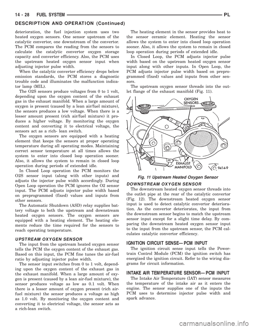
The upstream oxygen sensor threads into the out-
let flange of the exhaust manifold (Fig. 11).
DOWNSTREAM OXYGEN SENSOR
The downstream heated oxygen sensor threads into
the outlet pipe at the rear of the catalytic convertor
(Fig. 12). The downstream heated oxygen sensor
input is used to detect catalytic convertor deteriora-
tion. As the convertor deteriorates, the input from
the downstream sensor begins to match the upstream
sensor input except for a slight time delay. By com-
paring the downstream heated oxygen sensor input
to the input from the upstream sensor, the PCM cal-
culates catalytic convertor efficiency.
IGNITION CIRCUIT SENSEÐPCM INPUT
The ignition circuit sense input tells the Power-
train Control Module (PCM) the ignition switch has
energized the ignition circuit. Refer to the wiring dia-
grams for circuit information.
INTAKE AIR TEMPERATURE SENSORÐPCM INPUT
The Intake Air Temperature (IAT) sensor measures
the temperature of the intake air as it enters the
engine. The sensor supplies one of the inputs the
PCM uses to determine injector pulse width and
spark advance.
Fig. 11 Upstream Heated Oxygen Sensor
14 - 28 FUEL SYSTEMPL
DESCRIPTION AND OPERATION (Continued)