1999 DODGE NEON parking brake
[x] Cancel search: parking brakePage 8 of 1200
JUMP STARTING, TOWING AND HOISTING
INDEX
page page
SERVICE PROCEDURES
HOISTING RECOMMENDATIONS............ 9JUMP STARTING PROCEDURE.............. 7
TOWING RECOMMENDATIONS.............. 8
SERVICE PROCEDURES
JUMP STARTING PROCEDURE
WARNING: REVIEW ALL SAFETY PRECAUTIONS
AND WARNINGS IN GROUP 8A, BATTERY/START-
ING/CHARGING SYSTEMS DIAGNOSTICS. DO NOT
JUMP START A FROZEN BATTERY, PERSONAL
INJURY CAN RESULT. DO NOT JUMP START WHEN
MAINTENANCE FREE BATTERY INDICATOR DOT IS
YELLOW OR BRIGHT COLOR. DO NOT JUMP
START A VEHICLE WHEN THE BATTERY FLUID IS
BELOW THE TOP OF LEAD PLATES. DO NOT
ALLOW JUMPER CABLE CLAMPS TO TOUCH
EACH OTHER WHEN CONNECTED TO A BOOSTER
SOURCE. DO NOT USE OPEN FLAME NEAR BAT-
TERY. REMOVE METALLIC JEWELRY WORN ON
HANDS OR WRISTS TO AVOID INJURY BY ACCI-
DENTAL ARCING OF BATTERY CURRENT. WHEN
USING A HIGH OUTPUT BOOSTING DEVICE, DO
NOT ALLOW BATTERY VOLTAGE TO EXCEED 16
VOLTS. REFER TO INSTRUCTIONS PROVIDED
WITH DEVICE BEING USED.
CAUTION: When using another vehicle as a
booster, do not allow vehicles to touch. Electrical
systems can be damaged on either vehicle.
TO JUMP START A DISABLED VEHICLE:
(1) Raise hood on disabled vehicle and visually
inspect engine compartment for:
²Battery cable clamp condition, clean if necessary.
²Frozen battery.
²Yellow or bright color test indicator, if equipped.
²Low battery fluid level.
²Generator drive belt condition and tension.
²Fuel fumes or leakage, correct if necessary.
CAUTION: If the cause of starting problem on dis-
abled vehicle is severe, damage to booster vehicle
charging system can result.
(2) When using another vehicle as a booster
source, park the booster vehicle within cable reach.
Turn off all accessories, set the parking brake, placethe automatic transmission in PARK or the manual
transmission in NEUTRAL and turn the ignition
OFF.
(3) On disabled vehicle, place gear selector in park
or neutral and set park brake. Turn off all accesso-
ries.
(4) Connect jumper cables to booster battery. RED
clamp to positive terminal (+). BLACK clamp to neg-
ative terminal (-). DO NOT allow clamps at opposite
end of cables to touch, electrical arc will result.
Review all warnings in this procedure.
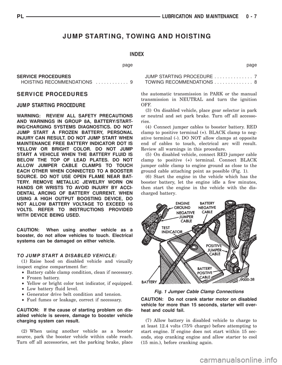
(5) On disabled vehicle, connect RED jumper cable
clamp to positive (+) terminal. Connect BLACK
jumper cable clamp to engine ground as close to the
ground cable attaching point as possible (Fig. 1).
(6) Start the engine in the vehicle which has the
booster battery, let the engine idle a few minutes,
then start the engine in the vehicle with the dis-
charged battery.
CAUTION: Do not crank starter motor on disabled
vehicle for more than 15 seconds, starter will over-
heat and could fail.
(7) Allow battery in disabled vehicle to charge to
at least 12.4 volts (75% charge) before attempting to
start engine. If engine does not start within 15 sec-
onds, stop cranking engine and allow starter to cool
(15 min.), before cranking again.
Fig. 1 Jumper Cable Clamp Connections
PLLUBRICATION AND MAINTENANCE 0 - 7
Page 83 of 1200
BASE BRAKE SYSTEM
INDEX
page page
DESCRIPTION AND OPERATION
CHASSIS TUBES AND HOSES.............. 6
FRONT DISC BRAKES..................... 2
MASTER CYLINDER...................... 6
PARKING BRAKES........................ 4
PROPORTIONING VALVES................. 5
REAR DISC BRAKES...................... 4
REAR DRUM BRAKES..................... 4
REAR WHEEL HUB/BEARING............... 8
RED BRAKE WARNING LAMP............... 7
STOP LAMP SWITCH...................... 8
VACUUM BOOSTER...................... 6
DIAGNOSIS AND TESTING
BRAKE FLUID CONTAMINATION............ 19
BRAKE SYSTEM BASIC DIAGNOSIS GUIDE.... 9
BRAKE SYSTEM DIAGNOSIS CHARTS....... 10
DRUM BRAKE AUTOMATIC ADJUSTER....... 14
PROPORTIONING VALVES................ 16
RED BRAKE WARNING LAMP TEST......... 19
ROTOR THICKNESS AND RUNOUT.......... 14
STOP LAMP SWITCH TEST PROCEDURE..... 19
SERVICE PROCEDURES
BRAKE BLEEDING....................... 20
BRAKE DRUM MACHINING................ 23
BRAKE FLUID LEVEL CHECK.............. 19
BRAKE ROTOR MACHINING............... 22
BRAKE TUBE REPAIR.................... 25
MASTER CYLINDER BLEEDING............ 21
PARK BRAKE LEVER AUTO ADJUSTER
MECHANISM.......................... 23
REMOVAL AND INSTALLATION
CHASSIS TUBES AND HOSES.............. 47
FRONT DISC BRAKE CALIPER............. 26
FRONT DISC BRAKE SHOES.............. 28
MASTER CYLINDER..................... 41
PARK BRAKE CABLES.................... 50
PARK BRAKE LEVER ASSEMBLY........... 48PARK BRAKE LEVER OUTPUT CABLE....... 49
PARK BRAKE SHOES WITH REAR DISC
BRAKES............................. 55
PROPORTIONING VALVE (BASE BRAKES).... 47
REAR BRAKE DRUM..................... 34
REAR BRAKE SHOE SUPPORT PLATE....... 37
REAR BRAKE SHOES.................... 35
REAR BRAKE WHEEL CYLINDER........... 38
REAR DISC BRAKE CALIPER.............. 30
REAR DISC BRAKE SHOES................ 32
REAR HUB/BEARING..................... 39
STOP LAMP SWITCH..................... 57
VACUUM BOOSTER..................... 44
WHEEL AND TIRE ASSEMBLY.............. 26
DISASSEMBLY AND ASSEMBLY
BRAKE FLUID LEVEL SWITCH............. 58
BRAKE FLUID RESERVOIR................ 57
FRONT AND REAR DISC BRAKE CALIPER.... 58
WHEEL CYLINDER (REAR DRUM BRAKE).... 63
CLEANING AND INSPECTION
CHASSIS TUBES AND HOSES.............. 65
FRONT DISC BRAKES.................... 63
REAR DISC BRAKES..................... 64
REAR DRUM BRAKE WHEEL CYLINDER...... 65
REAR DRUM BRAKES.................... 64
REAR WHEEL HUB AND BEARING ASSEMBLY . 65
ADJUSTMENTS
PARK BRAKE ADJUSTMENT............... 66
REAR DRUM BRAKE SHOE ADJUSTMENT.... 65
STOP LAMP SWITCH..................... 65
SPECIFICATIONS
BRAKE ACTUATION SYSTEM.............. 67
BRAKE FASTENER TORQUE SPECIFICATIONS . 67
BRAKE FLUID.......................... 67
SPECIAL TOOLS
BASE BRAKE SYSTEM................... 68
DESCRIPTION AND OPERATION
FRONT DISC BRAKES
The front disc brakes (Fig. 1) and (Fig. 2) consists
of the following components:
²The driving hub
²Braking disc (rotor)
²Caliper assembly - single piston, floating type
²Brake shoes and linings
The double pin calipers are mounted directly to the
steering knuckles and use no adapter. The caliper ismounted to the steering knuckle using bushings,
sleeves and 2 guide pin bolts which thread directly
into bosses on the steering knuckle (Fig. 2) and (Fig.
3).
Two machined abutments on the steering knuckle
position the caliper. The guide pin bolts, sleeves and
bushings control the side to side movement of the
caliper. The piston seal is designed to pull the piston
back into the bore of the caliper when the brake
pedal is released. This maintains the proper brake
shoe to rotor clearance (Fig. 4).
5 - 2 BRAKESPL
Page 85 of 1200
REAR DISC BRAKES
The rear disc brakes are similar to the front disc
brakes, however, there are several distinctive fea-
tures that require different service procedures. The
single piston, floating caliper rear disc brake assem-
bly includes a hub and bearing assembly, adapter,
brake rotor, caliper, brake pads/linings. The parking
brake system on all vehicles equipped with rear disc
brakes consists of a small duo-servo drum brake
mounted to the caliper adapter. The drum brake
shoes expand out against a braking surface (hat sec-
tion) on the inside area of the rotor.
Vehicles are equipped with a caliper assembly that
has a 34 mm (1.43 in.) piston and uses a solid non-
vented rotor.
The caliper assembly on all applications float on
rubber bushings using internal metal sleeves which
are attached to the adapter using threaded guide pin
bolts.
The adapter and rotor shield are mounted to the
rear suspension knuckles of vehicle. The adapter is
used to mount the brake shoes and actuating cables
for the parking brake system. The adapter also
mounts the rear caliper assembly to the vehicle. The
adapter has two machined abutments which are used
to position and align the caliper and brake pads for
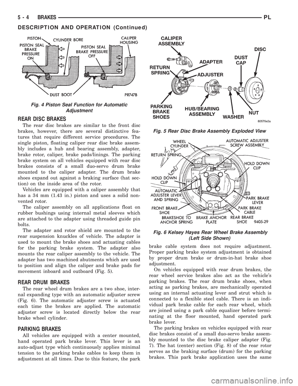
movement inboard and outboard (Fig. 5).
REAR DRUM BRAKES
The rear wheel drum brakes are a two shoe, inter-
nal expanding type with an automatic adjuster screw
(Fig. 6). The automatic adjuster screw is actuated
each time the brakes are applied. The automatic
adjuster screw is located directly below the rear
brake wheel cylinder.
PARKING BRAKES
All vehicles are equipped with a center mounted,
hand operated park brake lever. This lever is an
auto-adjust type which continuously applies minimal
tension to the parking brake cables to keep them in
adjustment at all times. Due to this feature, the parkbrake cable system does not require adjustment.
Proper parking brake system adjustment is obtained
by proper drum brake or drum-in-hat brake shoe
adjustment.
On vehicles equipped with rear drum brakes, the
rear wheel service brakes also act as the vehicle's
parking brakes. The rear drum brake shoes, when
acting as parking brakes, are mechanically operated
using an internal actuating lever and strut which is
connected to a flexible steel cable. There is an indi-
vidual park brake cable for each rear wheel, which
are joined using a park cable equalizer before termi-
nating at the floor mounted, hand operated park
brake lever.
The parking brakes on vehicles equipped with rear
disc brakes consist of a small duo-servo brake assem-
bly mounted to the disc brake caliper adapter (Fig.
7). The hat (center) section (Fig. 8) of the rear rotor
serves as the braking surface (drum) for the parking
brakes. This park brake application uses the same
Fig. 4 Piston Seal Function for Automatic
Adjustment
Fig. 5 Rear Disc Brake Assembly Exploded View
Fig. 6 Kelsey Hayes Rear Wheel Brake Assembly
(Left Side Shown)
5 - 4 BRAKESPL
DESCRIPTION AND OPERATION (Continued)
Page 88 of 1200
boosters differ at the interface to the master cylinder.
If the power brake booster requires replacement be
sure it is replaced with the correct part.
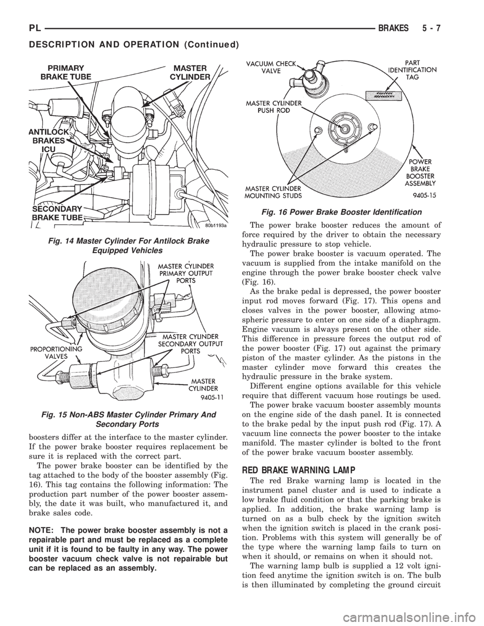
The power brake booster can be identified by the
tag attached to the body of the booster assembly (Fig.
16). This tag contains the following information: The
production part number of the power booster assem-
bly, the date it was built, who manufactured it, and
brake sales code.
NOTE: The power brake booster assembly is not a
repairable part and must be replaced as a complete
unit if it is found to be faulty in any way. The power
booster vacuum check valve is not repairable but
can be replaced as an assembly.The power brake booster reduces the amount of
force required by the driver to obtain the necessary
hydraulic pressure to stop vehicle.
The power brake booster is vacuum operated. The
vacuum is supplied from the intake manifold on the
engine through the power brake booster check valve
(Fig. 16).
As the brake pedal is depressed, the power booster
input rod moves forward (Fig. 17). This opens and
closes valves in the power booster, allowing atmo-
spheric pressure to enter on one side of a diaphragm.
Engine vacuum is always present on the other side.
This difference in pressure forces the output rod of
the power booster (Fig. 17) out against the primary
piston of the master cylinder. As the pistons in the
master cylinder move forward this creates the
hydraulic pressure in the brake system.
Different engine options available for this vehicle
require that different vacuum hose routings be used.
The power brake vacuum booster assembly mounts
on the engine side of the dash panel. It is connected
to the brake pedal by the input push rod (Fig. 17). A
vacuum line connects the power booster to the intake
manifold. The master cylinder is bolted to the front
of the power brake vacuum booster assembly.
RED BRAKE WARNING LAMP
The red Brake warning lamp is located in the
instrument panel cluster and is used to indicate a
low brake fluid condition or that the parking brake is
applied. In addition, the brake warning lamp is
turned on as a bulb check by the ignition switch
when the ignition switch is placed in the crank posi-
tion. Problems with this system will generally be of
the type where the warning lamp fails to turn on
when it should, or remains on when it should not.
The warning lamp bulb is supplied a 12 volt igni-
tion feed anytime the ignition switch is on. The bulb
is then illuminated by completing the ground circuit
Fig. 14 Master Cylinder For Antilock Brake
Equipped Vehicles
Fig. 15 Non-ABS Master Cylinder Primary And
Secondary Ports
Fig. 16 Power Brake Booster Identification
PLBRAKES 5 - 7
DESCRIPTION AND OPERATION (Continued)
Page 104 of 1200
The use of a double straddle cutter (Fig. 41) that
machines both sides of the rotor at the same time is
highly recommended.
RESURFACNG BRAKE ROTOR
This operation can be used when rotor surface is
rusty, has lining deposits or excessive lateral runout
or thickness variation is evident.
A sanding rotor attachment will remove surface
contamination without removing much rotor mate-
rial.
It will generally follow variations in thickness that
are in the rotor.
BRAKE DRUM MACHINING
Measure drum runout and diameter. If not to spec-
ification, reface drum. (Runout should not exceed
0.1524 mm or 0.006 inch). The diameter variation
(oval shape) of the drum braking surface must not
exceed either 0.0635 mm (0.0025 inch) in 30É or
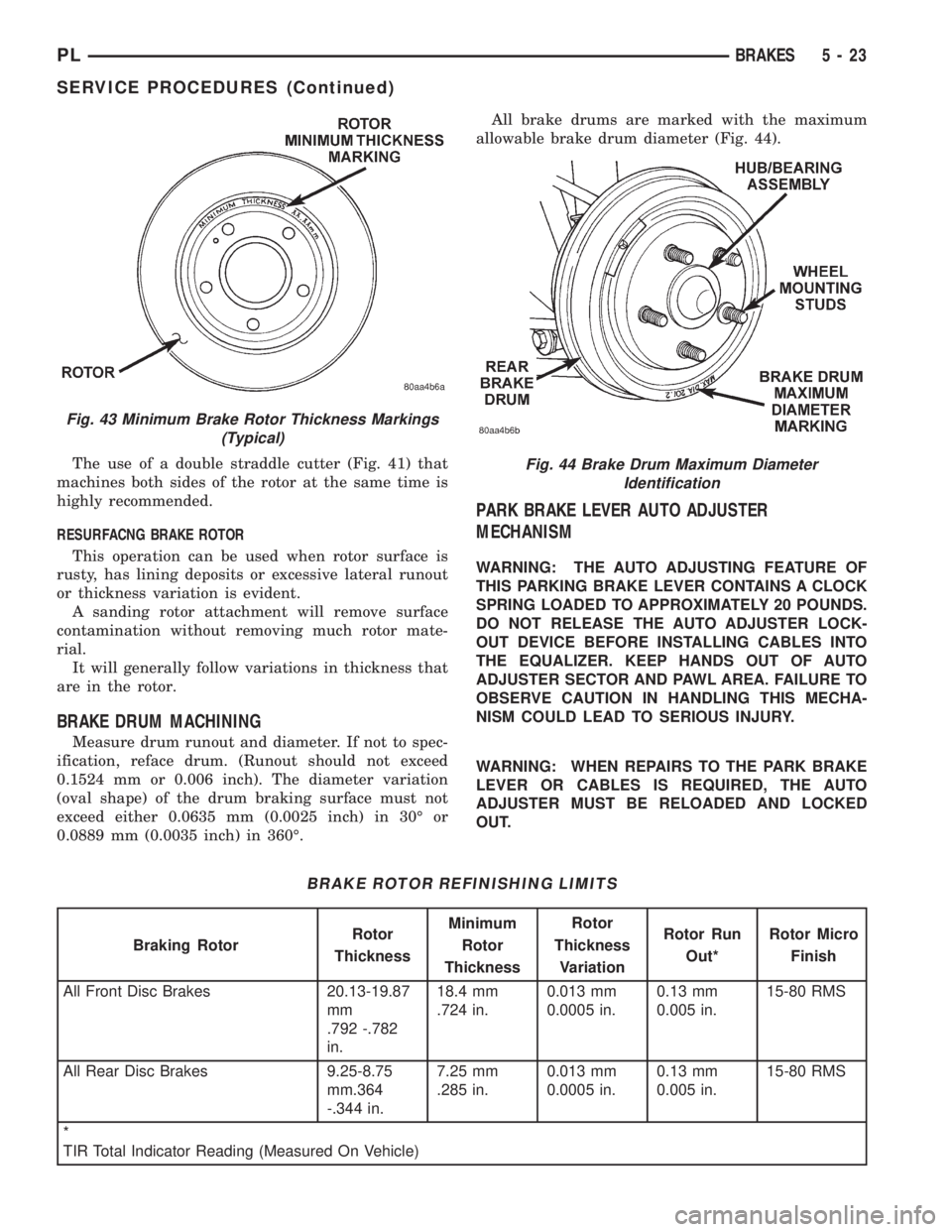
0.0889 mm (0.0035 inch) in 360É.All brake drums are marked with the maximum
allowable brake drum diameter (Fig. 44).
PARK BRAKE LEVER AUTO ADJUSTER
MECHANISM
WARNING: THE AUTO ADJUSTING FEATURE OF
THIS PARKING BRAKE LEVER CONTAINS A CLOCK
SPRING LOADED TO APPROXIMATELY 20 POUNDS.
DO NOT RELEASE THE AUTO ADJUSTER LOCK-
OUT DEVICE BEFORE INSTALLING CABLES INTO
THE EQUALIZER. KEEP HANDS OUT OF AUTO
ADJUSTER SECTOR AND PAWL AREA. FAILURE TO
OBSERVE CAUTION IN HANDLING THIS MECHA-
NISM COULD LEAD TO SERIOUS INJURY.
WARNING: WHEN REPAIRS TO THE PARK BRAKE
LEVER OR CABLES IS REQUIRED, THE AUTO
ADJUSTER MUST BE RELOADED AND LOCKED
OUT.
Fig. 43 Minimum Brake Rotor Thickness Markings
(Typical)
BRAKE ROTOR REFINISHING LIMITS
Braking RotorRotor
ThicknessMinimum
Rotor
ThicknessRotor
Thickness
VariationRotor Run
Out*Rotor Micro
Finish
All Front Disc Brakes 20.13-19.87
mm
.792 -.782
in.18.4 mm
.724 in.0.013 mm
0.0005 in.0.13 mm
0.005 in.15-80 RMS
All Rear Disc Brakes 9.25-8.75
mm.364
-.344 in.7.25 mm
.285 in.0.013 mm
0.0005 in.0.13 mm
0.005 in.15-80 RMS
*
TIR Total Indicator Reading (Measured On Vehicle)
Fig. 44 Brake Drum Maximum Diameter
Identification
PLBRAKES 5 - 23
SERVICE PROCEDURES (Continued)
Page 114 of 1200
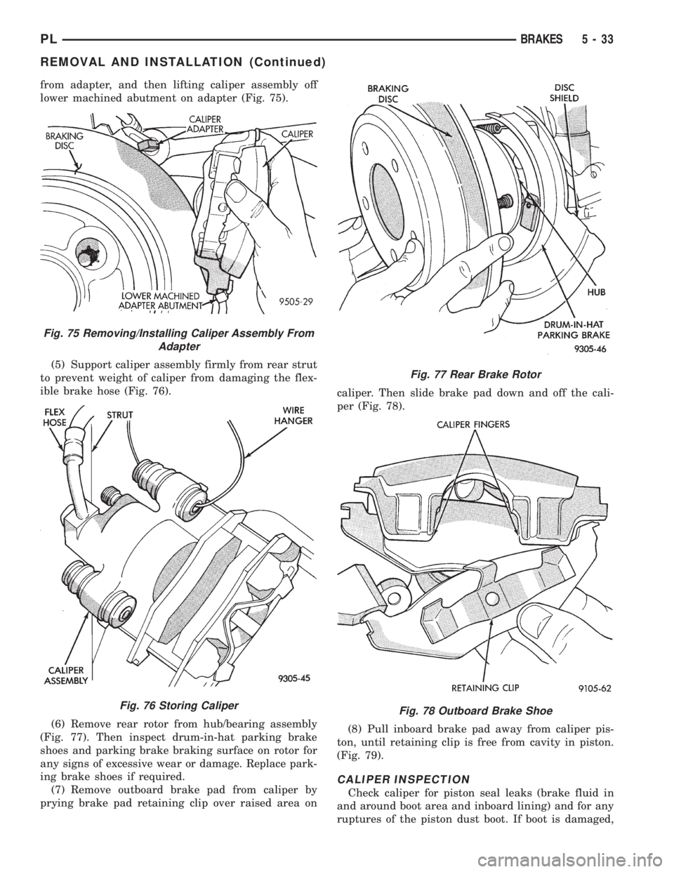
from adapter, and then lifting caliper assembly off
lower machined abutment on adapter (Fig. 75).
(5) Support caliper assembly firmly from rear strut
to prevent weight of caliper from damaging the flex-
ible brake hose (Fig. 76).
(6) Remove rear rotor from hub/bearing assembly
(Fig. 77). Then inspect drum-in-hat parking brake
shoes and parking brake braking surface on rotor for
any signs of excessive wear or damage. Replace park-
ing brake shoes if required.
(7) Remove outboard brake pad from caliper by
prying brake pad retaining clip over raised area oncaliper. Then slide brake pad down and off the cali-
per (Fig. 78).
(8) Pull inboard brake pad away from caliper pis-
ton, until retaining clip is free from cavity in piston.
(Fig. 79).
CALIPER INSPECTION
Check caliper for piston seal leaks (brake fluid in
and around boot area and inboard lining) and for any
ruptures of the piston dust boot. If boot is damaged,
Fig. 75 Removing/Installing Caliper Assembly From
Adapter
Fig. 76 Storing Caliper
Fig. 77 Rear Brake Rotor
Fig. 78 Outboard Brake Shoe
PLBRAKES 5 - 33
REMOVAL AND INSTALLATION (Continued)
Page 119 of 1200
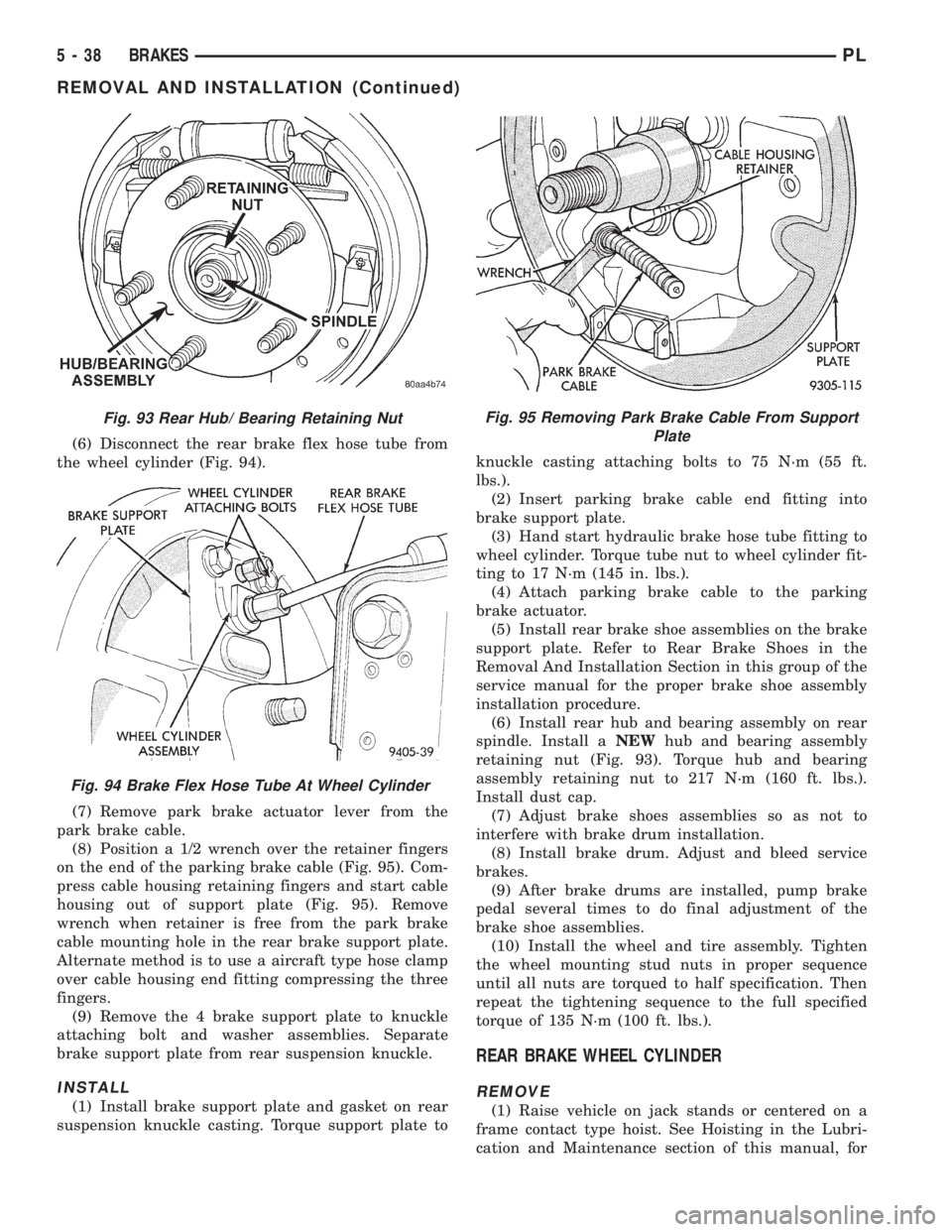
(6) Disconnect the rear brake flex hose tube from
the wheel cylinder (Fig. 94).
(7) Remove park brake actuator lever from the
park brake cable.
(8) Position a 1/2 wrench over the retainer fingers
on the end of the parking brake cable (Fig. 95). Com-
press cable housing retaining fingers and start cable
housing out of support plate (Fig. 95). Remove
wrench when retainer is free from the park brake
cable mounting hole in the rear brake support plate.
Alternate method is to use a aircraft type hose clamp
over cable housing end fitting compressing the three
fingers.
(9) Remove the 4 brake support plate to knuckle
attaching bolt and washer assemblies. Separate
brake support plate from rear suspension knuckle.
INSTALL
(1) Install brake support plate and gasket on rear
suspension knuckle casting. Torque support plate toknuckle casting attaching bolts to 75 N´m (55 ft.
lbs.).
(2) Insert parking brake cable end fitting into
brake support plate.
(3) Hand start hydraulic brake hose tube fitting to
wheel cylinder. Torque tube nut to wheel cylinder fit-
ting to 17 N´m (145 in. lbs.).
(4) Attach parking brake cable to the parking
brake actuator.
(5) Install rear brake shoe assemblies on the brake
support plate. Refer to Rear Brake Shoes in the
Removal And Installation Section in this group of the
service manual for the proper brake shoe assembly
installation procedure.
(6) Install rear hub and bearing assembly on rear
spindle. Install aNEWhub and bearing assembly
retaining nut (Fig. 93). Torque hub and bearing
assembly retaining nut to 217 N´m (160 ft. lbs.).
Install dust cap.
(7) Adjust brake shoes assemblies so as not to
interfere with brake drum installation.
(8) Install brake drum. Adjust and bleed service
brakes.
(9) After brake drums are installed, pump brake
pedal several times to do final adjustment of the
brake shoe assemblies.
(10) Install the wheel and tire assembly. Tighten
the wheel mounting stud nuts in proper sequence
until all nuts are torqued to half specification. Then
repeat the tightening sequence to the full specified
torque of 135 N´m (100 ft. lbs.).
REAR BRAKE WHEEL CYLINDER
REMOVE
(1) Raise vehicle on jack stands or centered on a
frame contact type hoist. See Hoisting in the Lubri-
cation and Maintenance section of this manual, for
Fig. 93 Rear Hub/ Bearing Retaining Nut
Fig. 94 Brake Flex Hose Tube At Wheel Cylinder
Fig. 95 Removing Park Brake Cable From Support
Plate
5 - 38 BRAKESPL
REMOVAL AND INSTALLATION (Continued)
Page 129 of 1200
PARK BRAKE LEVER ASSEMBLY
WARNING: THE AUTO ADJUSTING FEATURE OF
THIS PARKING BRAKE LEVER ASSEMBLY CON-
TAINS A CLOCK SPRING LOADED TO APPROXI-
MATELY 20 POUNDS. DO NOT RELEASE THE AUTO
ADJUSTER LOCKOUT DEVICE BEFORE INSTALL-
ING CABLES INTO THE EQUALIZER. KEEP HANDS
OUT OF AUTO ADJUSTER SECTOR AND PAWL
AREA. FAILURE TO OBSERVE CAUTION IN HAN-
DLING THIS MECHANISM COULD LEAD TO SERI-
OUS INJURY.
REMOVE
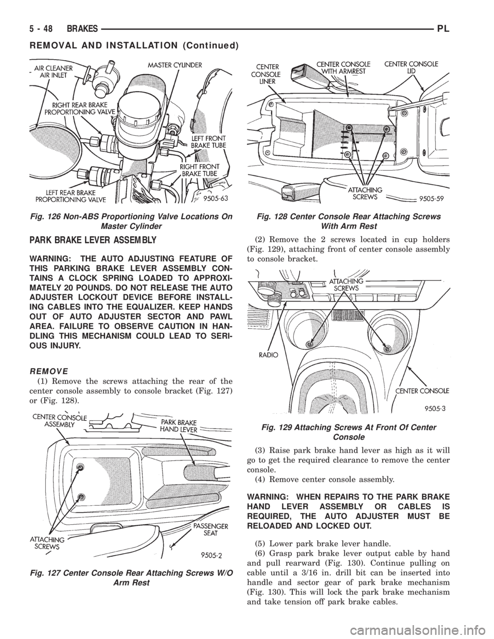
(1) Remove the screws attaching the rear of the
center console assembly to console bracket (Fig. 127)
or (Fig. 128).(2) Remove the 2 screws located in cup holders
(Fig. 129), attaching front of center console assembly
to console bracket.
(3) Raise park brake hand lever as high as it will
go to get the required clearance to remove the center
console.
(4) Remove center console assembly.
WARNING: WHEN REPAIRS TO THE PARK BRAKE
HAND LEVER ASSEMBLY OR CABLES IS
REQUIRED, THE AUTO ADJUSTER MUST BE
RELOADED AND LOCKED OUT.
(5) Lower park brake lever handle.
(6) Grasp park brake lever output cable by hand
and pull rearward (Fig. 130). Continue pulling on
cable until a 3/16 in. drill bit can be inserted into
handle and sector gear of park brake mechanism
(Fig. 130). This will lock the park brake mechanism
and take tension off park brake cables.
Fig. 126 Non-ABS Proportioning Valve Locations On
Master Cylinder
Fig. 127 Center Console Rear Attaching Screws W/O
Arm Rest
Fig. 128 Center Console Rear Attaching Screws
With Arm Rest
Fig. 129 Attaching Screws At Front Of Center
Console
5 - 48 BRAKESPL
REMOVAL AND INSTALLATION (Continued)