1999 DODGE NEON Cam gear
[x] Cancel search: Cam gearPage 15 of 1200
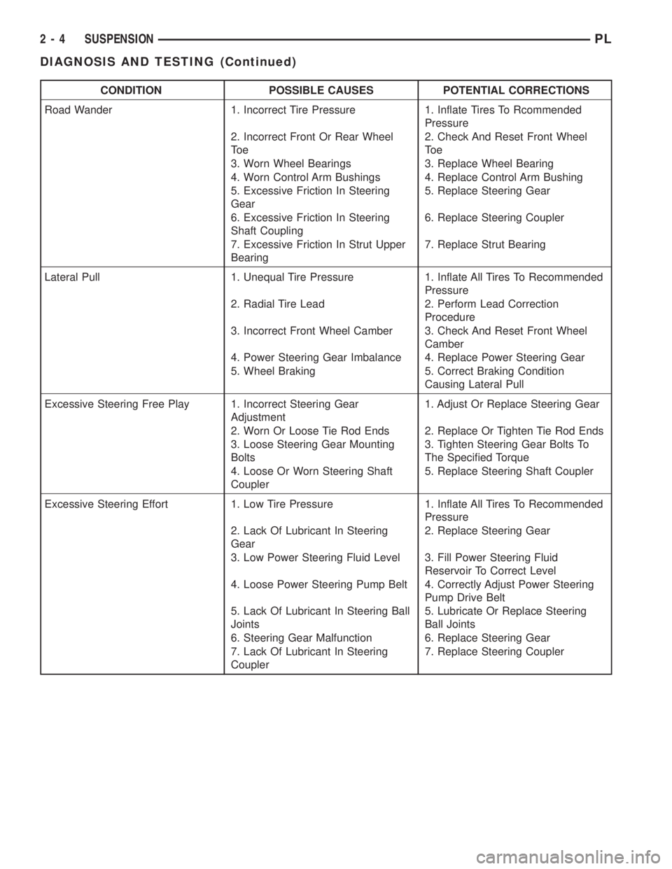
CONDITION POSSIBLE CAUSES POTENTIAL CORRECTIONS
Road Wander 1. Incorrect Tire Pressure 1. Inflate Tires To Rcommended
Pressure
2. Incorrect Front Or Rear Wheel
To e2. Check And Reset Front Wheel
To e
3. Worn Wheel Bearings 3. Replace Wheel Bearing
4. Worn Control Arm Bushings 4. Replace Control Arm Bushing
5. Excessive Friction In Steering
Gear5. Replace Steering Gear
6. Excessive Friction In Steering
Shaft Coupling6. Replace Steering Coupler
7. Excessive Friction In Strut Upper
Bearing7. Replace Strut Bearing
Lateral Pull 1. Unequal Tire Pressure 1. Inflate All Tires To Recommended
Pressure
2. Radial Tire Lead 2. Perform Lead Correction
Procedure
3. Incorrect Front Wheel Camber 3. Check And Reset Front Wheel
Camber
4. Power Steering Gear Imbalance 4. Replace Power Steering Gear
5. Wheel Braking 5. Correct Braking Condition
Causing Lateral Pull
Excessive Steering Free Play 1. Incorrect Steering Gear
Adjustment1. Adjust Or Replace Steering Gear
2. Worn Or Loose Tie Rod Ends 2. Replace Or Tighten Tie Rod Ends
3. Loose Steering Gear Mounting
Bolts3. Tighten Steering Gear Bolts To
The Specified Torque
4. Loose Or Worn Steering Shaft
Coupler5. Replace Steering Shaft Coupler
Excessive Steering Effort 1. Low Tire Pressure 1. Inflate All Tires To Recommended
Pressure
2. Lack Of Lubricant In Steering
Gear2. Replace Steering Gear
3. Low Power Steering Fluid Level 3. Fill Power Steering Fluid
Reservoir To Correct Level
4. Loose Power Steering Pump Belt 4. Correctly Adjust Power Steering
Pump Drive Belt
5. Lack Of Lubricant In Steering Ball
Joints5. Lubricate Or Replace Steering
Ball Joints
6. Steering Gear Malfunction 6. Replace Steering Gear
7. Lack Of Lubricant In Steering
Coupler7. Replace Steering Coupler
2 - 4 SUSPENSIONPL
DIAGNOSIS AND TESTING (Continued)
Page 16 of 1200
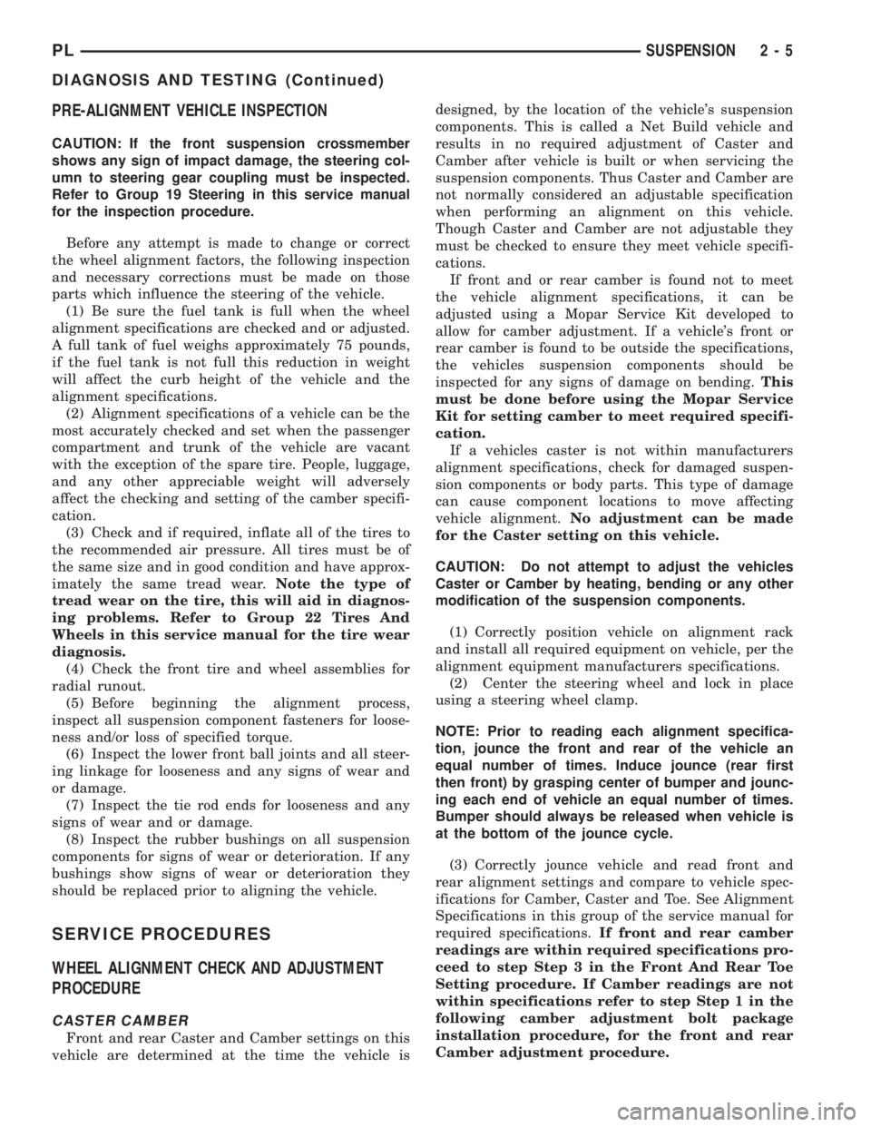
PRE-ALIGNMENT VEHICLE INSPECTION
CAUTION: If the front suspension crossmember
shows any sign of impact damage, the steering col-
umn to steering gear coupling must be inspected.
Refer to Group 19 Steering in this service manual
for the inspection procedure.
Before any attempt is made to change or correct
the wheel alignment factors, the following inspection
and necessary corrections must be made on those
parts which influence the steering of the vehicle.
(1) Be sure the fuel tank is full when the wheel
alignment specifications are checked and or adjusted.
A full tank of fuel weighs approximately 75 pounds,
if the fuel tank is not full this reduction in weight
will affect the curb height of the vehicle and the
alignment specifications.
(2) Alignment specifications of a vehicle can be the
most accurately checked and set when the passenger
compartment and trunk of the vehicle are vacant
with the exception of the spare tire. People, luggage,
and any other appreciable weight will adversely
affect the checking and setting of the camber specifi-
cation.
(3) Check and if required, inflate all of the tires to
the recommended air pressure. All tires must be of
the same size and in good condition and have approx-
imately the same tread wear.Note the type of
tread wear on the tire, this will aid in diagnos-
ing problems. Refer to Group 22 Tires And
Wheels in this service manual for the tire wear
diagnosis.
(4) Check the front tire and wheel assemblies for
radial runout.
(5) Before beginning the alignment process,
inspect all suspension component fasteners for loose-
ness and/or loss of specified torque.
(6) Inspect the lower front ball joints and all steer-
ing linkage for looseness and any signs of wear and
or damage.
(7) Inspect the tie rod ends for looseness and any
signs of wear and or damage.
(8) Inspect the rubber bushings on all suspension
components for signs of wear or deterioration. If any
bushings show signs of wear or deterioration they
should be replaced prior to aligning the vehicle.
SERVICE PROCEDURES
WHEEL ALIGNMENT CHECK AND ADJUSTMENT
PROCEDURE
CASTER CAMBER
Front and rear Caster and Camber settings on this
vehicle are determined at the time the vehicle isdesigned, by the location of the vehicle's suspension
components. This is called a Net Build vehicle and
results in no required adjustment of Caster and
Camber after vehicle is built or when servicing the
suspension components. Thus Caster and Camber are
not normally considered an adjustable specification
when performing an alignment on this vehicle.
Though Caster and Camber are not adjustable they
must be checked to ensure they meet vehicle specifi-
cations.
If front and or rear camber is found not to meet
the vehicle alignment specifications, it can be
adjusted using a Mopar Service Kit developed to
allow for camber adjustment. If a vehicle's front or
rear camber is found to be outside the specifications,
the vehicles suspension components should be
inspected for any signs of damage on bending.This
must be done before using the Mopar Service
Kit for setting camber to meet required specifi-
cation.
If a vehicles caster is not within manufacturers
alignment specifications, check for damaged suspen-
sion components or body parts. This type of damage
can cause component locations to move affecting
vehicle alignment.No adjustment can be made
for the Caster setting on this vehicle.
CAUTION: Do not attempt to adjust the vehicles
Caster or Camber by heating, bending or any other
modification of the suspension components.
(1) Correctly position vehicle on alignment rack
and install all required equipment on vehicle, per the
alignment equipment manufacturers specifications.
(2) Center the steering wheel and lock in place
using a steering wheel clamp.
NOTE: Prior to reading each alignment specifica-
tion, jounce the front and rear of the vehicle an
equal number of times. Induce jounce (rear first
then front) by grasping center of bumper and jounc-
ing each end of vehicle an equal number of times.
Bumper should always be released when vehicle is
at the bottom of the jounce cycle.
(3) Correctly jounce vehicle and read front and
rear alignment settings and compare to vehicle spec-
ifications for Camber, Caster and Toe. See Alignment
Specifications in this group of the service manual for
required specifications.If front and rear camber
readings are within required specifications pro-
ceed to step Step 3 in the Front And Rear Toe
Setting procedure. If Camber readings are not
within specifications refer to step Step 1 in the
following camber adjustment bolt package
installation procedure, for the front and rear
Camber adjustment procedure.
PLSUSPENSION 2 - 5
DIAGNOSIS AND TESTING (Continued)
Page 19 of 1200
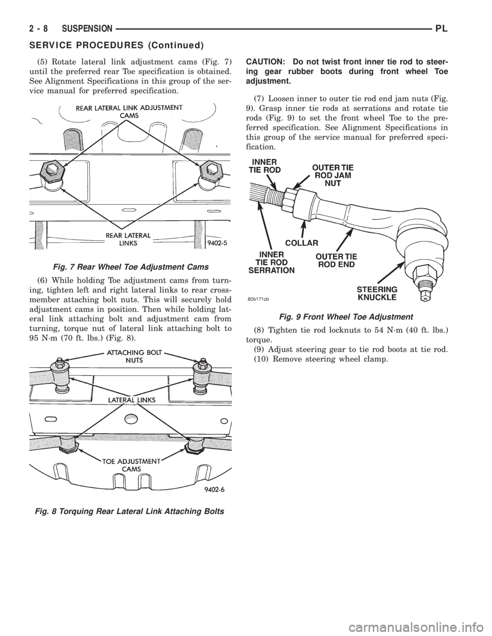
(5) Rotate lateral link adjustment cams (Fig. 7)
until the preferred rear Toe specification is obtained.
See Alignment Specifications in this group of the ser-
vice manual for preferred specification.
(6) While holding Toe adjustment cams from turn-
ing, tighten left and right lateral links to rear cross-
member attaching bolt nuts. This will securely hold
adjustment cams in position. Then while holding lat-
eral link attaching bolt and adjustment cam from
turning, torque nut of lateral link attaching bolt to
95 N´m (70 ft. lbs.) (Fig. 8).CAUTION: Do not twist front inner tie rod to steer-
ing gear rubber boots during front wheel Toe
adjustment.
(7) Loosen inner to outer tie rod end jam nuts (Fig.
9). Grasp inner tie rods at serrations and rotate tie
rods (Fig. 9) to set the front wheel Toe to the pre-
ferred specification. See Alignment Specifications in
this group of the service manual for preferred speci-
fication.
(8) Tighten tie rod locknuts to 54 N´m (40 ft. lbs.)
torque.
(9) Adjust steering gear to tie rod boots at tie rod.
(10) Remove steering wheel clamp.
Fig. 7 Rear Wheel Toe Adjustment Cams
Fig. 8 Torquing Rear Lateral Link Attaching Bolts
Fig. 9 Front Wheel Toe Adjustment
2 - 8 SUSPENSIONPL
SERVICE PROCEDURES (Continued)
Page 654 of 1200
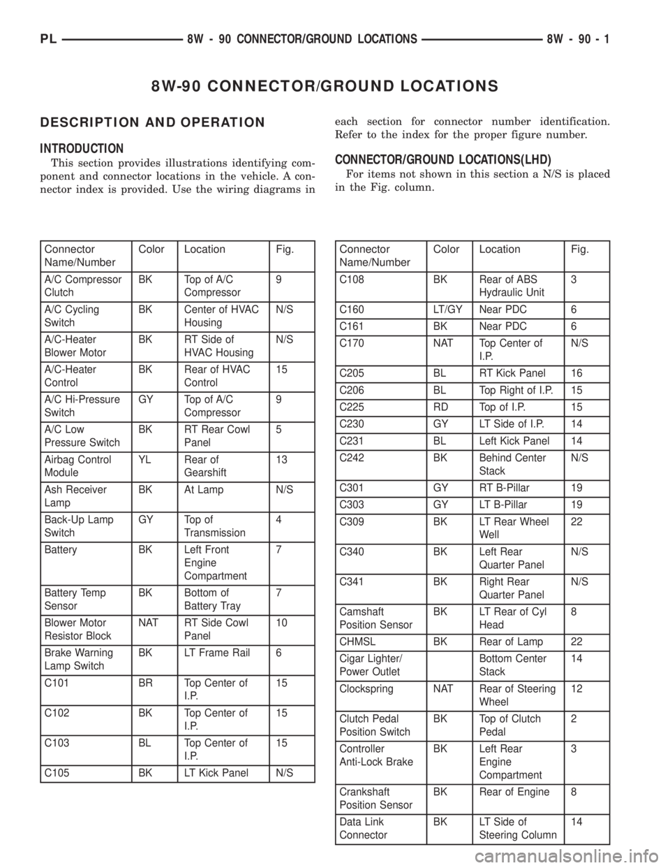
8W-90 CONNECTOR/GROUND LOCATIONS
DESCRIPTION AND OPERATION
INTRODUCTION
This section provides illustrations identifying com-
ponent and connector locations in the vehicle. A con-
nector index is provided. Use the wiring diagrams ineach section for connector number identification.
Refer to the index for the proper figure number.CONNECTOR/GROUND LOCATIONS(LHD)
For items not shown in this section a N/S is placed
in the Fig. column.
Connector
Name/NumberColor Location Fig.
A/C Compressor
ClutchBK Top of A/C
Compressor9
A/C Cycling
SwitchBK Center of HVAC
HousingN/S
A/C-Heater
Blower MotorBK RT Side of
HVAC HousingN/S
A/C-Heater
ControlBK Rear of HVAC
Control15
A/C Hi-Pressure
SwitchGY Top of A/C
Compressor9
A/C Low
Pressure SwitchBK RT Rear Cowl
Panel5
Airbag Control
ModuleYL Rear of
Gearshift13
Ash Receiver
LampBK At Lamp N/S
Back-Up Lamp
SwitchGY Top of
Transmission4
Battery BK Left Front
Engine
Compartment7
Battery Temp
SensorBK Bottom of
Battery Tray7
Blower Motor
Resistor BlockNAT RT Side Cowl
Panel10
Brake Warning
Lamp SwitchBK LT Frame Rail 6
C101 BR Top Center of
I.P.15
C102 BK Top Center of
I.P.15
C103 BL Top Center of
I.P.15
C105 BK LT Kick Panel N/S
Connector
Name/NumberColor Location Fig.
C108 BK Rear of ABS
Hydraulic Unit3
C160 LT/GY Near PDC 6
C161 BK Near PDC 6
C170 NAT Top Center of
I.P.N/S
C205 BL RT Kick Panel 16
C206 BL Top Right of I.P. 15
C225 RD Top of I.P. 15
C230 GY LT Side of I.P. 14
C231 BL Left Kick Panel 14
C242 BK Behind Center
StackN/S
C301 GY RT B-Pillar 19
C303 GY LT B-Pillar 19
C309 BK LT Rear Wheel
Well22
C340 BK Left Rear
Quarter PanelN/S
C341 BK Right Rear
Quarter PanelN/S
Camshaft
Position SensorBK LT Rear of Cyl
Head8
CHMSL BK Rear of Lamp 22
Cigar Lighter/
Power OutletBottom Center
Stack14
Clockspring NAT Rear of Steering
Wheel12
Clutch Pedal
Position SwitchBK Top of Clutch
Pedal2
Controller
Anti-Lock BrakeBK Left Rear
Engine
Compartment3
Crankshaft
Position SensorBK Rear of Engine 8
Data Link
ConnectorBK LT Side of
Steering Column14
PL8W - 90 CONNECTOR/GROUND LOCATIONS 8W - 90 - 1
Page 676 of 1200
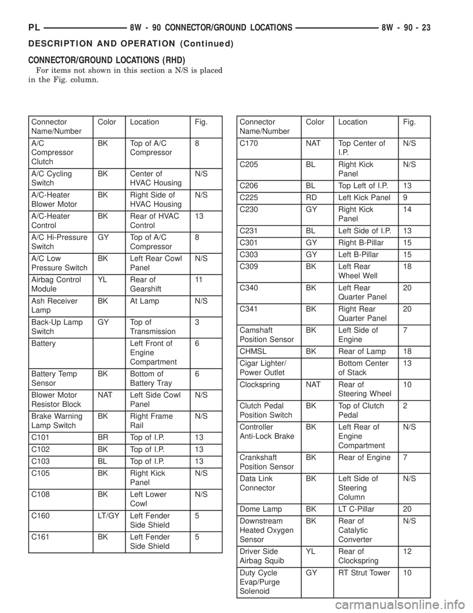
CONNECTOR/GROUND LOCATIONS (RHD)
For items not shown in this section a N/S is placed
in the Fig. column.
Connector
Name/NumberColor Location Fig.
A/C
Compressor
ClutchBK Top of A/C
Compressor8
A/C Cycling
SwitchBK Center of
HVAC HousingN/S
A/C-Heater
Blower MotorBK Right Side of
HVAC HousingN/S
A/C-Heater
ControlBK Rear of HVAC
Control13
A/C Hi-Pressure
SwitchGY Top of A/C
Compressor8
A/C Low
Pressure SwitchBK Left Rear Cowl
PanelN/S
Airbag Control
ModuleYL Rear of
Gearshift11
Ash Receiver
LampBK At Lamp N/S
Back-Up Lamp
SwitchGY Top of
Transmission3
Battery Left Front of
Engine
Compartment6
Battery Temp
SensorBK Bottom of
Battery Tray6
Blower Motor
Resistor BlockNAT Left Side Cowl
PanelN/S
Brake Warning
Lamp SwitchBK Right Frame
RailN/S
C101 BR Top of I.P. 13
C102 BK Top of I.P. 13
C103 BL Top of I.P. 13
C105 BK Right Kick
PanelN/S
C108 BK Left Lower
CowlN/S
C160 LT/GY Left Fender
Side Shield5
C161 BK Left Fender
Side Shield5Connector
Name/NumberColor Location Fig.
C170 NAT Top Center of
I.P.N/S
C205 BL Right Kick
PanelN/S
C206 BL Top Left of I.P. 13
C225 RD Left Kick Panel 9
C230 GY Right Kick
Panel14
C231 BL Left Side of I.P. 13
C301 GY Right B-Pillar 15
C303 GY Left B-Pillar 15
C309 BK Left Rear
Wheel Well18
C340 BK Left Rear
Quarter Panel20
C341 BK Right Rear
Quarter Panel20
Camshaft
Position SensorBK Left Side of
Engine7
CHMSL BK Rear of Lamp 18
Cigar Lighter/
Power OutletBottom Center
of Stack13
Clockspring NAT Rear of
Steering Wheel10
Clutch Pedal
Position SwitchBK Top of Clutch
Pedal2
Controller
Anti-Lock BrakeBK Left Rear of
Engine
CompartmentN/S
Crankshaft
Position SensorBK Rear of Engine 7
Data Link
ConnectorBK Left Side of
Steering
ColumnN/S
Dome Lamp BK LT C-Pillar 20
Downstream
Heated Oxygen
SensorBK Rear of
Catalytic
ConverterN/S
Driver Side
Airbag SquibYL Rear of
Clockspring12
Duty Cycle
Evap/Purge
SolenoidGY RT Strut Tower 10
PL8W - 90 CONNECTOR/GROUND LOCATIONS 8W - 90 - 23
DESCRIPTION AND OPERATION (Continued)
Page 832 of 1200
FRAMES
INDEX
page page
REMOVAL AND INSTALLATION
FRONT SUSPENSION CROSSMEMBER....... 3
SPECIFICATIONS
STRUCTURAL DIMENSIONS................ 4TORQUE SPECIFICATIONS................ 10
REMOVAL AND INSTALLATION
FRONT SUSPENSION CROSSMEMBER
WARNING: IF SUSPENSION CROSSMEMBER IS
REPLACED DUE TO COLLISION DAMAGE, INSPECT
THE STEERING COLUMN TO STEERING GEAR
COUPLING FOR DAMAGE. REFER TO GROUP 19,
STEERING FOR INSTRUCTIONS.
Before removing front suspension crossmem-
ber, index mark location of crossmember on
frame to aid installation.
The front suspension crossmember must be prop-
erly installed to achieve design camber, caster set-
tings and wheel stagger. The crossmember can be
installed out of position on the frame rails due to its
design. Bolts and cage nuts hold the rear of the
crossmember to the frame torque boxes. Bolts and
J-nuts hold the front of the crossmember to the
frame rails. No designed in locating device is used to
position the crossmember in the vehicle. Before
removing the crossmember mark the frame torque
box around the rear mounting location to aid instal-
lation. A crossmember that is removed during service
must be installed in the same position from which it
was removed. To verify that crossmember is in the
proper position, refer to the dimensions provided.
Front end dimensions are gauged from the principal
locating point (PLP) holes located under the frame
torque boxes rearward of the front wheels. After
removal and installation of the crossmember is per-
formed, verify that front suspension alignment is
within specifications. If camber, caster settings and
wheel stagger is not within specifications, loosen and
reposition crossmember to bring suspension within
specifications. Refer to Group 2, Front Suspension
and Driveshaft for additional information.
REMOVAL
(1) Hoist and support vehicle on safety stands.
(2) Using a suitable marking device, mark the out-
line of the suspension crossmember on the frame
torque box around the rear mounting location.(3) Remove front wheels from vehicle.
(4) Remove pinch bolts holding front ball joints to
spindles.
(5) Separate ball joints from spindles.
(6) Position a suitable lifting device under the
crossmember.
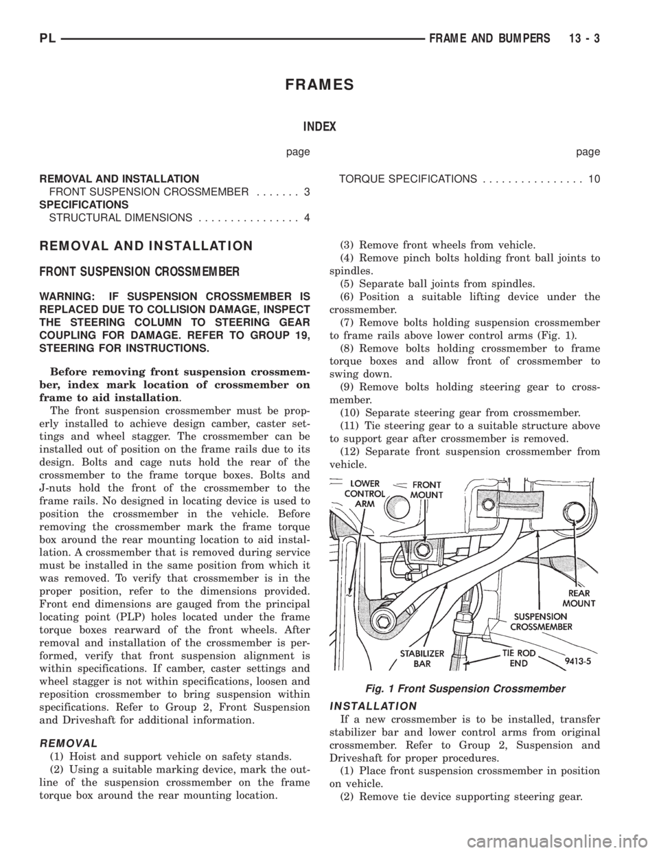
(7) Remove bolts holding suspension crossmember
to frame rails above lower control arms (Fig. 1).
(8) Remove bolts holding crossmember to frame
torque boxes and allow front of crossmember to
swing down.
(9) Remove bolts holding steering gear to cross-
member.
(10) Separate steering gear from crossmember.
(11) Tie steering gear to a suitable structure above
to support gear after crossmember is removed.
(12) Separate front suspension crossmember from
vehicle.
INSTALLATION
If a new crossmember is to be installed, transfer
stabilizer bar and lower control arms from original
crossmember. Refer to Group 2, Suspension and
Driveshaft for proper procedures.
(1) Place front suspension crossmember in position
on vehicle.
(2) Remove tie device supporting steering gear.
Fig. 1 Front Suspension Crossmember
PLFRAME AND BUMPERS 13 - 3
Page 833 of 1200
(3) Place steering gear in position on crossmember.
(4) Install bolts to hold steering gear to crossmem-
ber.
(5) Position lifting device under the crossmember.
(6) Lift crossmember to frame rails.
(7) Engage bolts to hold crossmember rear mounts
into cage nuts in the frame torque boxes. Do not
tighten bolts.
(8) Install bolts to hold crossmember to frame rails
above lower control arms.
(9) Lower and remove lifting device.
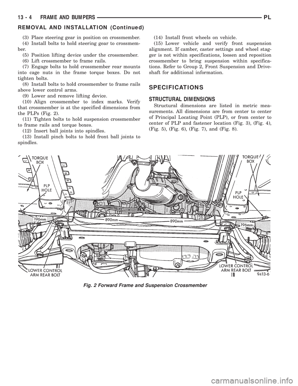
(10) Align crossmember to index marks. Verify
that crossmember is at the specified dimensions from
the PLPs (Fig. 2).
(11) Tighten bolts to hold suspension crossmember
to frame rails and torque boxes.
(12) Insert ball joints into spindles.
(13) Install pinch bolts to hold front ball joints to
spindles.(14) Install front wheels on vehicle.
(15) Lower vehicle and verify front suspension
alignment. If camber, caster settings and wheel stag-
ger is not within specifications, loosen and reposition
crossmember to bring suspension within specifica-
tions. Refer to Group 2, Front Suspension and Drive-
shaft for additional information.
SPECIFICATIONS
STRUCTURAL DIMENSIONS
Structural dimensions are listed in metric mea-
surements. All dimensions are from center to center
of Principal Locating Point (PLP), or from center to
center of PLP and fastener location (Fig. 3), (Fig. 4),
(Fig. 5), (Fig. 6), (Fig. 7), and (Fig. 8).
Fig. 2 Forward Frame and Suspension Crossmember
13 - 4 FRAME AND BUMPERSPL
REMOVAL AND INSTALLATION (Continued)
Page 865 of 1200

POWERTRAIN CONTROL MODULE
The Powertrain Control Module (PCM) is a digital
computer containing a microprocessor (Fig. 2). The
PCM receives input signals from various switches
and sensors that are referred to as PCM Inputs.
Based on these inputs, the PCM adjusts various
engine and vehicle operations through devices that
are referred to as PCM Outputs.
PCM Inputs:
²Air Conditioning Controls
²Battery Voltage
²Battery Temperature Sensor
²Brake Switch
²Camshaft Position Sensor
²Crankshaft Position Sensor
²Engine Coolant Temperature Sensor
²Fuel Level Sensor
²Ignition Switch
²Intake Air Temperature Sensor
²Knock Sensor
²Manifold Absolute Pressure (MAP) Sensor
²Oxygen Sensors
²Power Steering Pressure Switch
²SCI Receive
²Speed Control Switches
²Throttle Position Sensor
²Transmission Park/Neutral Switch (automatic
transmission)
²Vehicle Speed Sensor
PCM Outputs:
²Air Conditioning WOT Relay
²Auto Shutdown (ASD) Relay
²Charging Indicator Lamp
²Data Link Connector
²Duty Cycle EVAP Canister Purge Solenoid
²EGR Solenoid
²Fuel Injectors
²Fuel Pump Relay²Generator Field
²Idle Air Control Motor
²Ignition Coils
²Malfunction Indicator (Check Engine) Lamp
²Radiator Fan Relay
²Speed Control Solenoids
²Tachometer
²Torque Convertor Clutch Solenoid
Based on inputs it receives, the PCM adjusts fuel
injector pulse width, idle speed, ignition spark
advance, ignition coil dwell and EVAP canister purge
operation. The PCM regulates the cooling fan, air
conditioning and speed control systems. The PCM
changes generator charge rate by adjusting the gen-
erator field. The PCM also performs diagnostics.
The PCM adjusts injector pulse width (air-fuel
ratio) based on the following inputs.
²Battery voltage
²Coolant temperature
²Intake air temperature
²Exhaust gas content (oxygen sensor)
²Engine speed (crankshaft position sensor)
²Manifold absolute pressure
²Throttle position
The PCM adjusts ignition timing based on the fol-
lowing inputs.
²Coolant temperature
²Intake air temperature
²Engine speed (crankshaft position sensor)
²Knock sensor
²Manifold absolute pressure
²Throttle position
²Transmission gear selection (park/neutral
switch)
The PCM also adjusts engine idle speed through
the idle air control motor based on the following
inputs.
²Air conditioning sense
²Battery voltage
²Battery temperature
²Brake switch
²Coolant temperature
²Engine speed (crankshaft position sensor)
²Engine run time
²Manifold absolute pressure
²Power steering pressure switch
²Throttle position
²Transmission gear selection (park/neutral
switch)
²Vehicle distance (speed)
The Auto Shutdown (ASD) and fuel pump relays
are mounted externally, but turned on and off by the
PCM.
The crankshaft position sensor signal is sent to the
PCM. If the PCM does not receive the signal within
approximately one second of engine cranking, it deac-
Fig. 2 Powertrain Control Module (PCM)
14 - 24 FUEL SYSTEMPL
DESCRIPTION AND OPERATION (Continued)