1999 DODGE NEON width
[x] Cancel search: widthPage 117 of 1200
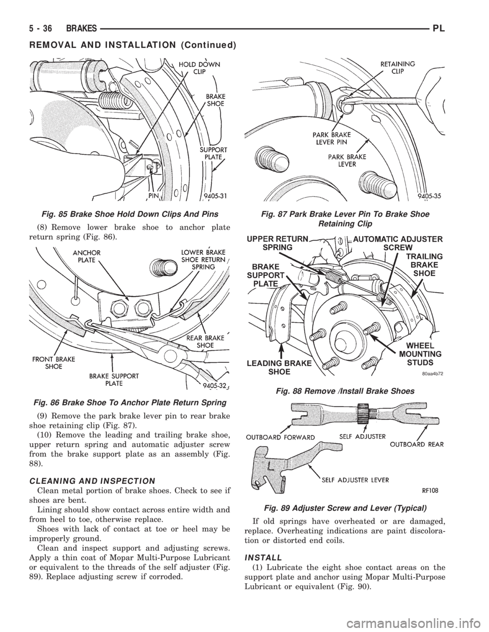
(8) Remove lower brake shoe to anchor plate
return spring (Fig. 86).
(9) Remove the park brake lever pin to rear brake
shoe retaining clip (Fig. 87).
(10) Remove the leading and trailing brake shoe,
upper return spring and automatic adjuster screw
from the brake support plate as an assembly (Fig.
88).
CLEANING AND INSPECTION
Clean metal portion of brake shoes. Check to see if
shoes are bent.
Lining should show contact across entire width and
from heel to toe, otherwise replace.
Shoes with lack of contact at toe or heel may be
improperly ground.
Clean and inspect support and adjusting screws.
Apply a thin coat of Mopar Multi-Purpose Lubricant
or equivalent to the threads of the self adjuster (Fig.
89). Replace adjusting screw if corroded.If old springs have overheated or are damaged,
replace. Overheating indications are paint discolora-
tion or distorted end coils.
INSTALL
(1) Lubricate the eight shoe contact areas on the
support plate and anchor using Mopar Multi-Purpose
Lubricant or equivalent (Fig. 90).
Fig. 85 Brake Shoe Hold Down Clips And Pins
Fig. 86 Brake Shoe To Anchor Plate Return Spring
Fig. 87 Park Brake Lever Pin To Brake Shoe
Retaining Clip
Fig. 88 Remove /Install Brake Shoes
Fig. 89 Adjuster Screw and Lever (Typical)
5 - 36 BRAKESPL
REMOVAL AND INSTALLATION (Continued)
Page 145 of 1200
is damaged, or a fluid leak is visible, disassemble cal-
iper assembly and install a new seal and boot, and
piston if scored. Refer to Front Disc Brake Caliper in
the Disassembly And Assembly Section in this group
of the service manual.
Check the guide pin dust boots to determine if they
are in good condition. Replace if they are damaged,
dry, or found to be brittle. Refer to Front Disc Brake
Caliper in the Disassembly And Assembly Section in
this group of the service manual.
REAR DISC BRAKES
BRAKE PAD LINING WEAR
If a visual inspection does not adequately deter-
mine the condition of the lining, a physical check will
be necessary. To check the amount of lining wear,
remove the wheel and tire assemblies, and the cali-
pers.
Remove the rear disc brake shoes. Refer to Rear
Disc Brake Shoe Removal in the Removal And Instal-
lation section in this group of the service manual for
the required procedure.
The combined brake shoe and lining material
thickness should be measured at the thinnest part of
the assembly.
When a set of brake shoes are worn to a total
thickness of approximately 7.0 mm (9/32 inch) they
should be replaced.
Replacebothbrake shoe assemblies (inboard and
outboard). It is necessary thatbothrear wheel sets
be replaced whenever brake shoe assemblies on
either side are replaced.
If the brake shoe assemblies do not require
replacement, reinstall, the assemblies making sureeach brake shoe is returned to the original position.
Refer to Rear Disc Brake Shoe Installation in the
Removal And Installation section in this group of the
service manual for the required procedure.
CALIPER INSPECTION
Check for brake fluid leaks in and around boot
area and inboard lining, and for any ruptures, brit-
tleness or damage to the piston dust boot. If the boot
is damaged, or a fluid leak is visible, disassemble cal-
iper assembly and install a new seal and boot, and
piston if scored. Refer to Rear Disc Brake Caliper in
the Disassembly And Assembly Section in this group
of the service manual.
Check the guide pin dust boots to determine if they
are in good condition. Replace if they are damaged,
dry, or found to be brittle. Refer to Rear Disc Brake
Caliper in the Disassembly And Assembly Section in
this group of the service manual.
REAR DRUM BRAKES
Rear brake shoe lining should show contact across
entire width of the lining and also from the heel to
the toe of the lining, otherwise replace.
Brake shoes with lack of contact at the toe or heel
of the brake shoe linng may be improperly ground.
Clean and inspect the brake support plate and
adjusting screws. Apply a thin coat of Mopar Multi-
Purpose Lubricant or equivalent to the threads of the
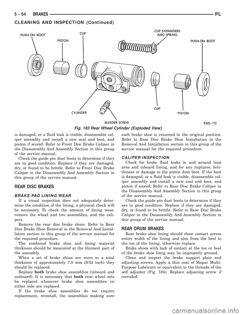
self adjuster (Fig. 184). Replace adjusting screw if
corroded.
Fig. 183 Rear Wheel Cylinder (Exploded View)
5 - 64 BRAKESPL
CLEANING AND INSPECTION (Continued)
Page 253 of 1200
CRANKSHAFT POSITION SENSOR
The PCM determines what cylinder to fire from the
crankshaft position sensor input and the camshaft
position sensor input. The second crankshaft counter-
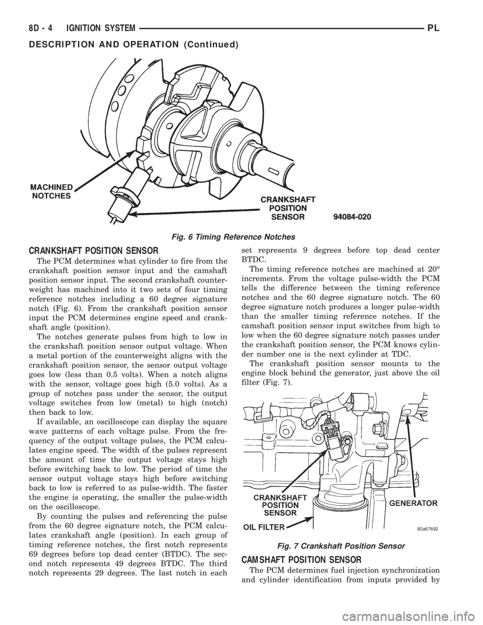
weight has machined into it two sets of four timing
reference notches including a 60 degree signature
notch (Fig. 6). From the crankshaft position sensor
input the PCM determines engine speed and crank-
shaft angle (position).
The notches generate pulses from high to low in
the crankshaft position sensor output voltage. When
a metal portion of the counterweight aligns with the
crankshaft position sensor, the sensor output voltage
goes low (less than 0.5 volts). When a notch aligns
with the sensor, voltage goes high (5.0 volts). As a
group of notches pass under the sensor, the output
voltage switches from low (metal) to high (notch)
then back to low.
If available, an oscilloscope can display the square
wave patterns of each voltage pulse. From the fre-
quency of the output voltage pulses, the PCM calcu-
lates engine speed. The width of the pulses represent
the amount of time the output voltage stays high
before switching back to low. The period of time the
sensor output voltage stays high before switching
back to low is referred to as pulse-width. The faster
the engine is operating, the smaller the pulse-width
on the oscilloscope.
By counting the pulses and referencing the pulse
from the 60 degree signature notch, the PCM calcu-
lates crankshaft angle (position). In each group of
timing reference notches, the first notch represents
69 degrees before top dead center (BTDC). The sec-
ond notch represents 49 degrees BTDC. The third
notch represents 29 degrees. The last notch in eachset represents 9 degrees before top dead center
BTDC.
The timing reference notches are machined at 20É
increments. From the voltage pulse-width the PCM
tells the difference between the timing reference
notches and the 60 degree signature notch. The 60
degree signature notch produces a longer pulse-width
than the smaller timing reference notches. If the
camshaft position sensor input switches from high to
low when the 60 degree signature notch passes under
the crankshaft position sensor, the PCM knows cylin-
der number one is the next cylinder at TDC.
The crankshaft position sensor mounts to the
engine block behind the generator, just above the oil
filter (Fig. 7).
CAMSHAFT POSITION SENSOR
The PCM determines fuel injection synchronization
and cylinder identification from inputs provided by
Fig. 6 Timing Reference Notches
Fig. 7 Crankshaft Position Sensor
8D - 4 IGNITION SYSTEMPL
DESCRIPTION AND OPERATION (Continued)
Page 255 of 1200

SOHC
The coolant sensor threads into the end of the cyl-
inder head, next to the camshaft position sensor (Fig.
12). New sensors have sealant applied to the threads.
DOHC
The coolant sensor threads into the intake mani-
fold next to the thermostat housing (Fig. 13). New
sensors have sealant applied to the threads.
INTAKE AIR TEMPERATURE SENSOR
The intake air temperature sensor measures the
temperature of the air as it enters the engine. The
sensor supplies one of the inputs the PCM uses to
determine injector pulse-width.
The MAP/Intake Air Temperature (IAT) sensor,
located on the intake manifold, combines the MAP
and Intake Air Temperature (IAT) functions into one
sensor (Fig. 14) or (Fig. 15).
KNOCK SENSOR
The knock sensor threads into the side of the cyl-
inder block in front of the starter motor. When the
knock sensor detects a knock in one of the cylinders,
it sends an input signal to the PCM. In response, the
PCM retards ignition timing for all cylinders by a
scheduled amount.
Knock sensors contain a piezoelectric material
which constantly vibrates and sends an input voltage
(signal) to the PCM while the engine operates. As the
intensity of the crystal's vibration increase, the knock
sensor output voltage also increases.
NOTE: Over or under tightening effects knock sen-
sor performance, possibly causing improper spark
control.
MANIFOLD ABSOLUTE PRESSURE SENSOR (MAP)
The PCM supplies 5 volts to the MAP sensor. The
MAP sensor function converts intake manifold pres-
sure into voltage. The PCM monitors the MAP sensor
output voltage. As vacuum increases, MAP sensor
voltage decreases proportionately. Also, as vacuum
decreases, MAP sensor voltage increases proportion-
ately.
Key on, before the engine starts running, the PCM
determines atmospheric air pressure from the MAP
sensor voltage. While the engine operates, the PCM
determines intake manifold pressure from the MAP
sensor voltage. Based on MAP sensor voltage and
inputs from other sensors, the PCM adjusts spark
advance and the air/fuel mixture.
The MAP/IAT sensor mounts to the intake mani-
fold (Fig. 14) or (Fig. 15).
THROTTLE POSITION SENSOR (TPS)
The TPS mounts to the side of the throttle body.
The TPS connects to the throttle blade shaft. The
TPS is a variable resistor that provides the Power-
Fig. 12 Engine Coolant Temperature SensorÐSOHC
Fig. 13 Engine Coolant Temperature SensorÐDOHC
Fig. 14 MAP/IAT sensorÐSOHC
8D - 6 IGNITION SYSTEMPL
DESCRIPTION AND OPERATION (Continued)
Page 256 of 1200
train Control Module (PCM) with an input signal
(voltage). The signal represents throttle blade posi-
tion. As the position of the throttle blade changes,
the resistance of the TPS changes.
The PCM supplies approximately 5 volts to the
TPS. The TPS output voltage (input signal to the
powertrain control module) represents throttle blade
position. The TPS output voltage to the PCM varies
from approximately 0.38 volts to 1.2 volts at mini-
mum throttle opening (idle) to a maximum of 3.1
volts to 4.4 volts at wide open throttle.
Along with inputs from other sensors, the PCM
uses the TPS input to determine current engine oper-
ating conditions. The PCM also adjusts fuel injector
pulse width and ignition timing based on these
inputs.
IGNITION SWITCH
In the RUN position, the ignition switch connects
power from the Power Distribution Center (PDC) to a
30 amp fuse in the fuse block, back to a bus bar in
the PDC. The bus bar feeds circuits for the Power-
train Control Module (PCM), duty cycle purge sole-
noid, EGR solenoid, and ABS system. The bus bar in
the PDC feeds the coil side of the radiator fan relay,
A/C compressor clutch relay, and the fuel pump relay.
It also feeds the Airbag Control Module (ACM)
LOCK KEY CYLINDER
The lock cylinder is inserted in the end of the
housing opposite the ignition switch. The ignition key
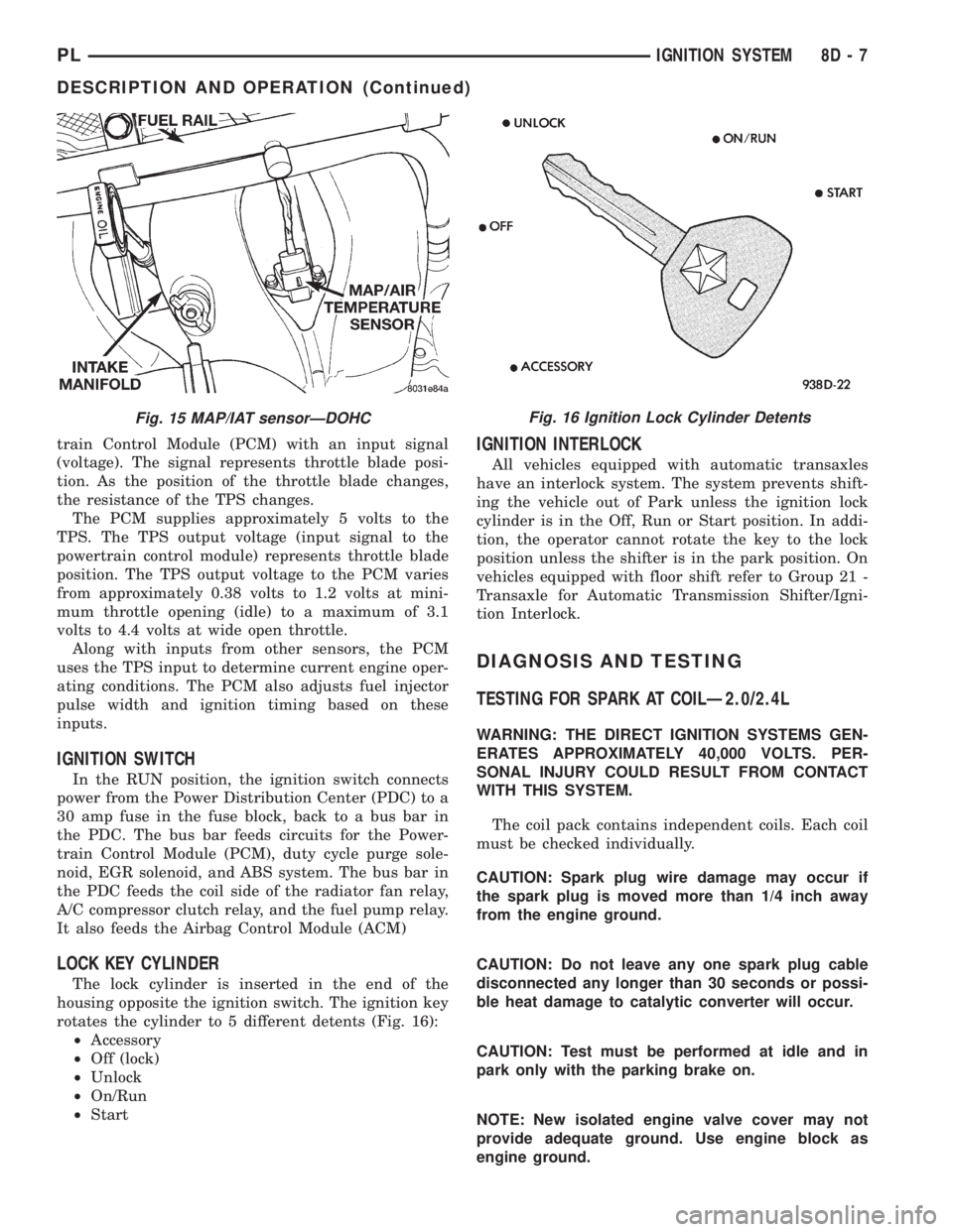
rotates the cylinder to 5 different detents (Fig. 16):
²Accessory
²Off (lock)
²Unlock
²On/Run
²Start
IGNITION INTERLOCK
All vehicles equipped with automatic transaxles
have an interlock system. The system prevents shift-
ing the vehicle out of Park unless the ignition lock
cylinder is in the Off, Run or Start position. In addi-
tion, the operator cannot rotate the key to the lock
position unless the shifter is in the park position. On
vehicles equipped with floor shift refer to Group 21 -
Transaxle for Automatic Transmission Shifter/Igni-
tion Interlock.
DIAGNOSIS AND TESTING
TESTING FOR SPARK AT COILÐ2.0/2.4L
WARNING: THE DIRECT IGNITION SYSTEMS GEN-
ERATES APPROXIMATELY 40,000 VOLTS. PER-
SONAL INJURY COULD RESULT FROM CONTACT
WITH THIS SYSTEM.
The coil pack contains independent coils. Each coil
must be checked individually.
CAUTION: Spark plug wire damage may occur if
the spark plug is moved more than 1/4 inch away
from the engine ground.
CAUTION: Do not leave any one spark plug cable
disconnected any longer than 30 seconds or possi-
ble heat damage to catalytic converter will occur.
CAUTION: Test must be performed at idle and in
park only with the parking brake on.
NOTE: New isolated engine valve cover may not
provide adequate ground. Use engine block as
engine ground.
Fig. 15 MAP/IAT sensorÐDOHCFig. 16 Ignition Lock Cylinder Detents
PLIGNITION SYSTEM 8D - 7
DESCRIPTION AND OPERATION (Continued)
Page 714 of 1200
ENGINE
CONTENTS
page page
2.0L DOHC ENGINE...................... 58
2.0L SOHC ENGINE...................... 12ENGINE DIAGNOSIS....................... 7
STANDARD SERVICE PROCEDURES.......... 1
STANDARD SERVICE PROCEDURES
INDEX
page page
GENERAL INFORMATION
CHECKING ENGINE OIL LEVEL.............. 5
CRANKSHAFT SPROCKET BOLT ACCESS
PLUG................................ 2
ENGINE CORE PLUGS.................... 2
ENGINE OIL SERVICE..................... 5
ENGINE PERFORMANCE.................. 2FORM-IN-PLACE GASKETS................. 1
HONING CYLINDER BORES................ 3
HYDROSTATIC LOCKED ENGINE............ 4
MEASURING MAIN BEARING AND
CONNECTING ROD BEARING CLEARANCES . 3
REPAIR OF DAMAGED OR WORN THREADS . . . 4
GENERAL INFORMATION
FORM-IN-PLACE GASKETS
There are numerous places where form-in-place
gaskets are used on the engine. Care must be taken
when applying form-in-place gaskets to assure
obtaining the desired results.Do not use form-in-
place gasket material unless specified.Bead size,
continuity, and location are of great importance. Too
thin a bead can result in leakage while too much can
result in spill-over which can break off and obstruct
fluid feed lines. A continuous bead of the proper
width is essential to obtain a leak-free gasket.
There are numerous types of form-in-place gasket
materials that are used in the engine area. Mopart
Silicone Rubber Adhesive Sealant and MopartGas-
ket Maker gasket materials, each have different
properties and can not be used in place of the other.
MOPARtSILICONE RUBBER ADHESIVE
SEALANT
MopartSilicone Rubber Adhesive Sealant or equiv-
alent, normally black in color, is available in three
ounce tubes. Moisture in the air causes the Mopart
Silicone Rubber Adhesive Sealant material to cure.
This material is normally used on flexible metal
flanges. It has a shelf life of one year and will not
properly cure if over age. Always inspect the package
for the expiration date before use.MOPARtGASKET MAKER
MopartGasket Maker is an anaerobic type gasket
material. The material cures in the absence of air
when squeezed between two metallic surfaces. It will
not cure if left in the uncovered tube. The anaerobic
material is for use between two machined surfaces.
Do not use on flexible metal flanges.
MOPARtTORQUE CURE GASKET MAKER
MopartTorque Cure Gasket Maker is a unique
anaerobic type gasket material to be usedONLY
between the bedplate and engine block. The material
cures in the absence of air when torqued between
two metallic surfaces. It will not cure if left in the
uncovered tube. This anaerobic material is specially
made to seal the area between the bedplate and cyl-
inder block without disturbing the bearing clearance
or alignment of these components.
GASKET DISASSEMBLY
Parts assembled with form-in-place gaskets may be
disassembled without unusual effort. In some
instances, it may be necessary to lightly tap the part
with a mallet or other suitable tool to break the seal
between the mating surfaces. A flat gasket scraper
may also be lightly tapped into the joint but care
must be taken not to damage the mating surfaces.
SURFACE PREPARATION
Scrape clean or wire brush all gasket surfaces
removing all loose material. Inspect stamped parts to
PLENGINE 9 - 1
Page 717 of 1200
²When checking #3 main bearing shim #2 & #4
main bearing.
²When checking #4 main bearing shim #3 main
bearing.
NOTE: REMOVE ALL SHIMS BEFORE REASSEM-
BLING ENGINE
ALTERNATIVE METHOD
The weight of the crankshaft can be supported by a
jack under the counterweight adjacent to the bearing
being checked.
PLASTIGAGE PROCEDURE
(1) Remove oil film from surface to be checked.
Plastigage is soluble in oil.
(2) Place a piece of Plastigage across the entire
width of the bearing shell in the cap approximately
6.35 mm (1/4 in.) off center and away from the oil
holes (Fig. 3). (In addition, suspected areas can be
checked by placing the Plastigage in the suspected
area). Torque the bearing cap bolts of the bearing
being checked to the proper specifications.
(3) Remove the bearing cap and compare the
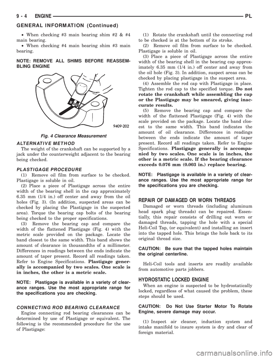
width of the flattened Plastigage (Fig. 4) with the
metric scale provided on the package. Locate the
band closest to the same width. This band shows the
amount of clearance in thousandths of a millimeter.
Differences in readings between the ends indicate the
amount of taper present. Record all readings taken.
Refer to Engine Specifications.Plastigage gener-
ally is accompanied by two scales. One scale is
in inches, the other is a metric scale.
NOTE: Plastigage is available in a variety of clear-
ance ranges. Use the most appropriate range for
the specifications you are checking.
CONNECTING ROD BEARING CLEARANCE
Engine connecting rod bearing clearances can be
determined by use of Plastigage or equivalent. The
following is the recommended procedure for the use
of Plastigage:(1) Rotate the crankshaft until the connecting rod
to be checked is at the bottom of its stroke.
(2) Remove oil film from surface to be checked.
Plastigage is soluble in oil.
(3) Place a piece of Plastigage across the entire
width of the bearing shell in the bearing cap approx-
imately 6.35 mm (1/4 in.) off center and away from
the oil hole (Fig. 3). In addition, suspect areas can be
checked by placing plastigage in the suspect area.
(4) Assemble the rod cap with Plastigage in place.
Tighten the rod cap to the specified torque.Do not
rotate the crankshaft while assembling the cap
or the Plastigage may be smeared, giving inac-
curate results.
(5) Remove the bearing cap and compare the
width of the flattened Plastigage (Fig. 4) with the
scale provided on the package. Locate the band clos-
est to the same width. This band indicates the
amount of oil clearance. Differences in readings
between the ends indicate the amount of taper
present. Record all readings taken. Refer to Engine
Specifications.Plastigage generally is accompa-
nied by two scales. One scale is in inches, the
other is a metric scale. If the bearing clearance
exceeds 0.076 mm (0.003 in.) replace bearing.
NOTE: Plastigage is available in a variety of clear-
ance ranges. Use the most appropriate range for
the specifications you are checking.
REPAIR OF DAMAGED OR WORN THREADS
Damaged or worn threads (including aluminum
head spark plug threads) can be repaired. Essen-
tially, this repair consists of drilling out worn or
damaged threads, tapping the hole with a special
Heli-Coil Tap, (or equivalent) and installing an insert
into the tapped hole. This brings the hole back to its
original thread size.
CAUTION: Be sure that the tapped holes maintain
the original centerline.
Heli-Coil tools and inserts are readily available
from automotive parts jobbers.
HYDROSTATIC LOCKED ENGINE
When an engine is suspected to be hydrostatically
locked, regardless of what caused the problem, these
steps should be used.
CAUTION: Do Not Use Starter Motor To Rotate
Engine, severe damage may occur.
(1) Inspect air cleaner, induction system and
intake manifold to insure system is dry and clear of
foreign material.
Fig. 4 Clearance Measurement
9 - 4 ENGINEPL
GENERAL INFORMATION (Continued)
Page 724 of 1200

ENGINE DIAGNOSISÐMECHANICAL
CONDITION POSSIBLE CAUSES CORRECTION
NOISY VALVES 1. High or low oil level in crankcase. 1. Check for correct oil level.
2. Thin or diluted oil. 2. Change oil to correct viscosity.
3. Low oil pressure. 3. Check engine oil level.
4. Dirt in tappets/lash adjusters. 4. Replace rocker arm/hydraulic lash adjuster
assembly.
5. Worn rocker arms. 5. Inspect oil supply to rocker arms.
6. Worn tappets/lash adjusters. 6. Install new rocker arm/hydraulic lash adjuster
assembly.
7. Worn valve guides. 7. Ream and install new valves with oversize
stems.
8. Excessive runout of valve seats on valve faces. 8. Grind valve seats and valves.
9. Missing adjuster pivot. 9. Replace rocker arm/hydraulic lash adjuster
assembly.
CONNECTING ROD
NOISE1. Insuffient oil supply. 1. Check engine oil level.
2. Low oil pressure. 2. Check engine oil level. Inspect oil pump relief
valve and spring.
3. Thin or diluted oil. 3. Change oil to correct viscosity.
4. Excessive bearing clearance. 4. Measure bearings for correct clearance. Repair
as necessary.
5. Connecting rod journal out-of-round. 5. Replace crankshaft or grind surface.
6. Misaligned connecting rods. 6. Replace bent connecting rods.
MAIN BEARING NOISE 1. Insufficient oil supply. 1. Check engine oil level.
2. Low oil pressure. 2. Check engine oil level. Inspect oil pump relief
valve and spring.
3. Thin or diluted oil. 3. Change oil to correct viscosity.
4. Excessive bearing clearance. 4. Measure bearings for correct clearance. Repair
as necessary.
5. Excessive end play. 5. Check thrust bearing for wear on flanges.
6. Crankshaft journal out-of-round or worn. 6. Replace crankshaft or grind journals.
7. Loose flywheel or torque converter. 7. Tighten to correct torque.
OIL PRESSURE DROP 1. Low oil level. 1. Check engine oil level.
2. Faulty oil pressure sending unit. 2. Install new sending unit.
3. Low oil pressure. 3. Check sending unit and main bearing oil
clearance.
4. Clogged oil filter. 4. Install new oil filter.
5. Worn parts in oil pump. 5. Replace worn parts or pump.
6. Thin or diluted oil. 6. Change oil to correct viscosity.
7. Excessive bearing clearance. 7. Measure bearings for correct clearance.
8. Oil pump relief valve stuck. 8. Remove valve and inspect, clean, or replace.
9. Oil pump suction tube loose. 9. Remove oil pan and install new tube or clean, if
necessary.
10. Oil pump cover warped or cracked. 10. Install new oil pump.
OIL LEAKS 1. Misaligned or deteriorated gaskets. 1. Replace gasket(s).
2. Loose fastener, broken or porous metal part. 2. Tighten, repair or replace the part.
3. Misaligned or deteriorated cup or threaded plug. 3. Replace as necessary.
OIL CONSUMPTION
OR SPARK PLUGS
FOULED1. PCV system malfunction. 1. Check system and repair as necessary. Refer to
Group 25, Emission Control Systems.
2. Worn, scuffed or broken rings. 2. Hone cyinder bores. Install new rings.
3. Carbon in oil ring slots. 3. Install new rings.
4. Rings fitted too tightly in grooves. 4. Remove rings and check grooves. If groove is
not proper width, replace piston.
5. Worn valve guides. 5. Ream guides and replace valves with oversize
valves and seals.
6. Valve stem seal unseated or faulty. 6. Repair or replace seal.
PLENGINE 9 - 11
DIAGNOSIS AND TESTING (Continued)