1999 DODGE NEON compression ratio
[x] Cancel search: compression ratioPage 24 of 1200
COMPETITION PACKAGE SUSPENSION
On vehicles that are equipped with the optional
competition package, special front struts are used.
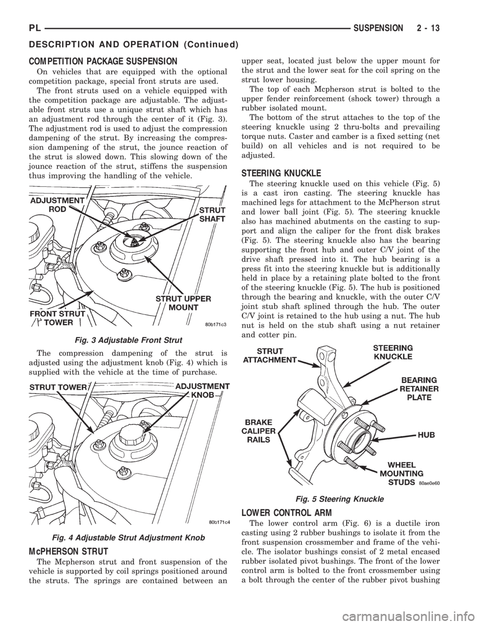
The front struts used on a vehicle equipped with
the competition package are adjustable. The adjust-
able front struts use a unique strut shaft which has
an adjustment rod through the center of it (Fig. 3).
The adjustment rod is used to adjust the compression
dampening of the strut. By increasing the compres-
sion dampening of the strut, the jounce reaction of
the strut is slowed down. This slowing down of the
jounce reaction of the strut, stiffens the suspension
thus improving the handling of the vehicle.
The compression dampening of the strut is
adjusted using the adjustment knob (Fig. 4) which is
supplied with the vehicle at the time of purchase.
McPHERSON STRUT
The Mcpherson strut and front suspension of the
vehicle is supported by coil springs positioned around
the struts. The springs are contained between anupper seat, located just below the upper mount for
the strut and the lower seat for the coil spring on the
strut lower housing.
The top of each Mcpherson strut is bolted to the
upper fender reinforcement (shock tower) through a
rubber isolated mount.
The bottom of the strut attaches to the top of the
steering knuckle using 2 thru-bolts and prevailing
torque nuts. Caster and camber is a fixed setting (net
build) on all vehicles and is not required to be
adjusted.
STEERING KNUCKLE
The steering knuckle used on this vehicle (Fig. 5)
is a cast iron casting. The steering knuckle has
machined legs for attachment to the McPherson strut
and lower ball joint (Fig. 5). The steering knuckle
also has machined abutments on the casting to sup-
port and align the caliper for the front disk brakes
(Fig. 5). The steering knuckle also has the bearing
supporting the front hub and outer C/V joint of the
drive shaft pressed into it. The hub bearing is a
press fit into the steering knuckle but is additionally
held in place by a retaining plate bolted to the front
of the steering knuckle (Fig. 5). The hub is positioned
through the bearing and knuckle, with the outer C/V
joint stub shaft splined through the hub. The outer
C/V joint is retained to the hub using a nut. The hub
nut is held on the stub shaft using a nut retainer
and cotter pin.
LOWER CONTROL ARM
The lower control arm (Fig. 6) is a ductile iron
casting using 2 rubber bushings to isolate it from the
front suspension crossmember and frame of the vehi-
cle. The isolator bushings consist of 2 metal encased
rubber isolated pivot bushings. The front of the lower
control arm is bolted to the front crossmember using
a bolt through the center of the rubber pivot bushing
Fig. 3 Adjustable Front Strut
Fig. 4 Adjustable Strut Adjustment Knob
Fig. 5 Steering Knuckle
PLSUSPENSION 2 - 13
DESCRIPTION AND OPERATION (Continued)
Page 52 of 1200
COMPETITION PACKAGE SUSPENSION
On vehicles that are equipped with the optional
competition package, special rear struts are used.
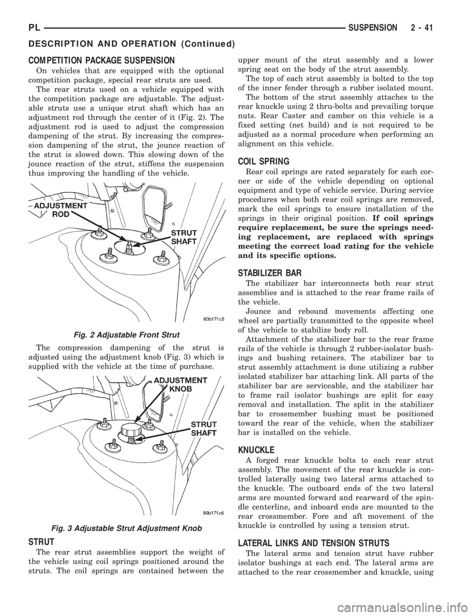
The rear struts used on a vehicle equipped with
the competition package are adjustable. The adjust-
able struts use a unique strut shaft which has an
adjustment rod through the center of it (Fig. 2). The
adjustment rod is used to adjust the compression
dampening of the strut. By increasing the compres-
sion dampening of the strut, the jounce reaction of
the strut is slowed down. This slowing down of the
jounce reaction of the strut, stiffens the suspension
thus improving the handling of the vehicle.
The compression dampening of the strut is
adjusted using the adjustment knob (Fig. 3) which is
supplied with the vehicle at the time of purchase.
STRUT
The rear strut assemblies support the weight of
the vehicle using coil springs positioned around the
struts. The coil springs are contained between theupper mount of the strut assembly and a lower
spring seat on the body of the strut assembly.
The top of each strut assembly is bolted to the top
of the inner fender through a rubber isolated mount.
The bottom of the strut assembly attaches to the
rear knuckle using 2 thru-bolts and prevailing torque
nuts. Rear Caster and camber on this vehicle is a
fixed setting (net build) and is not required to be
adjusted as a normal procedure when performing an
alignment on this vehicle.
COIL SPRING
Rear coil springs are rated separately for each cor-
ner or side of the vehicle depending on optional
equipment and type of vehicle service. During service
procedures when both rear coil springs are removed,
mark the coil springs to ensure installation of the
springs in their original position.If coil springs
require replacement, be sure the springs need-
ing replacement, are replaced with springs
meeting the correct load rating for the vehicle
and its specific options.
STABILIZER BAR
The stabilizer bar interconnects both rear strut
assemblies and is attached to the rear frame rails of
the vehicle.
Jounce and rebound movements affecting one
wheel are partially transmitted to the opposite wheel
of the vehicle to stabilize body roll.
Attachment of the stabilizer bar to the rear frame
rails of the vehicle is through 2 rubber-isolator bush-
ings and bushing retainers. The stabilizer bar to
strut assembly attachment is done utilizing a rubber
isolated stabilizer bar attaching link. All parts of the
stabilizer bar are serviceable, and the stabilizer bar
to frame rail isolator bushings are split for easy
removal and installation. The split in the stabilizer
bar to crossmember bushing must be positioned
toward the rear of the vehicle, when the stabilizer
bar is installed on the vehicle.
KNUCKLE
A forged rear knuckle bolts to each rear strut
assembly. The movement of the rear knuckle is con-
trolled laterally using two lateral arms attached to
the knuckle. The outboard ends of the two lateral
arms are mounted forward and rearward of the spin-
dle centerline, and inboard ends are mounted to the
rear crossmember. Fore and aft movement of the
knuckle is controlled by using a tension strut.
LATERAL LINKS AND TENSION STRUTS
The lateral arms and tension strut have rubber
isolator bushings at each end. The lateral arms are
attached to the rear crossmember and knuckle, using
Fig. 2 Adjustable Front Strut
Fig. 3 Adjustable Strut Adjustment Knob
PLSUSPENSION 2 - 41
DESCRIPTION AND OPERATION (Continued)
Page 723 of 1200

ENGINE DIAGNOSISÐPERFORMANCE
CONDITION POSSIBLE CAUSE CORRECTION
ENGINE WILL NOT
START1. Weak battery. 1. Test battery. Charge or replace as necessary.
Refer to Group 8A, Battery.
2. Corroded or loose battery connections. 2. Clean and tighten battery connections. Apply a
coat of light mineral grease to terminals.
3. Faulty starter. Test starting system. Refer to Group 8B, Starting.
4. Moisture on ignition wires. 4. Remove moisture from wires.
5. Faulty ignition cables. 5. Replace any cracked or shorted cables.
6. Faulty coil or control unit. 6. Test and replace as needed. Refer to Group 8D,
Ignition System
7. Incorrect spark plug gap. 7. Set gap. Refer to Group 8D, Ignition System.
8. Contamination in fuel system. 8. Clean system and replace fuel filter.
9. Faulty fuel pump. 9. Test fuel pump and replace as needed. Refer to
Group 14, Fuel System.
ENGINE STALLS OR
IDLES ROUGH1. Idle speed too low. 1. Test minimum air flow. Refer to Group 14, Fuel
System.
2. Incorrect fuel mixture. 2. Refer to Group 14, Fuel System.
3. Intake manifold leakage. 3. Inspect intake manifold, manifold gasket, and
vacuum hoses. Refer to Group 11, Exhaust System
and Intake Manifold.
4. Incorrect ignition wiring. 4. Install correct wiring.
5. Faulty coil(s) 5. Test and replace as necessary. Refer to Group
8D, Ignition System.
ENGINE LOSS OF
POWER1. Dirty or incorrectly gapped plugs. 1. Clean plugs and set gap. Refer to Group 8D,
Ignition System.
2. Contamination in fuel system. 2. Clean system and replace fuel filter.
3. Faulty fuel pump. 3. Test and replace as necessary. Refer to Group
14, Fuel System.
4. Incorrect valve timing. 4. Correct valve timing.
5. Leaking cylinder head gasket. 5. Replace cylinder head gasket.
6. Low compression. 6. Test compression of each cylinder.
7. Burned, warped, or pitted valves. 7. Replace valves.
8. Plugged or restricted exhaust system. 8. Install new parts, as necessary.
9. Faulty ignition cables. 9. Replace any cracked or shorted cables.
10. Faulty coil(s). 10. Test and replace as necessary. Refer to Group
8D, Ignition System.
ENGINE MISSES ON
ACCELERATION1. Dirty or incorrectly gapped spark plugs. 1. Clean spark plugs and set gap. Refer to Group
8D, Ignition System.
2. Contamination in Fuel System. 2. Clean fuel system and replace fuel filter.
3. Burned, warped, or pitted valves. 3. Replace valves.
4. Faulty coil(s). 4. Test and replace as necessary. Refer to Group
8D, Ignition System.
ENGINE MISSES AT
HIGH SPEED1. Dirty or incorrect spark plug gap. 1. Clean spark plugs and set gap. Refer to Group
8D, Ignition System.
2. Faulty coil(s). 2. Test and replace as necessary. Refer to Group
8D, Ignition System.
3. Dirty fuel injector(s). Test and replace as necessary. Refer to Group 14,
Fuel System.
4. Contamination in fuel system. 4. Clean system and replace fuel filter.
9 - 10 ENGINEPL
DIAGNOSIS AND TESTING (Continued)
Page 725 of 1200
2.0L SOHC ENGINE
INDEX
page page
DESCRIPTION AND OPERATION
ENGINE COMPONENTS.................. 14
ENGINE IDENTIFICATION................. 12
ENGINE LUBRICATION SYSTEM............ 13
GENERAL SPECIFICATION................ 12
DIAGNOSIS AND TESTING
CHECKING ENGINE OIL PRESSURE......... 14
SERVICE PROCEDURES
CRANKSHAFT END PLAY................. 16
CYLINDER BORE AND PISTON SIZING....... 14
FITTING CONNECTING RODS.............. 16
FITTING CRANKSHAFT BEARINGS.......... 16
FITTING PISTON RINGS.................. 16
REMOVAL AND INSTALLATION
CAMSHAFT OIL SEAL.................... 28
CAMSHAFT............................ 22
CRANKSHAFT DAMPER.................. 46
CRANKSHAFT OIL SEALÐFRONT........... 37
CRANKSHAFT OIL SEALÐREAR............ 38
CRANKSHAFT.......................... 39
CYLINDER HEAD COVER................. 21
CYLINDER HEAD........................ 25
ENGINE ASSEMBLY...................... 19
ENGINE MOUNTÐFRONT................. 18
ENGINE MOUNTÐLEFT................... 18
ENGINE MOUNTÐRIGHT................. 18
OIL FILTER ADAPTER.................... 42OILFILTER ............................ 42
OILPAN ............................... 36
OIL PUMP............................. 42
PISTON AND CONNECTING ROD........... 44
POWER HOP DAMPER................... 18
ROCKER ARM/HYDRAULIC LASH ADJUSTER . . 23
SPARK PLUG TUBE...................... 21
STRUCTURAL COLLARÐ2.0L.............. 19
TIMING BELT COVER.................... 27
TIMING BELT TENSIONERÐMECHANICAL.... 36
TIMING BELTÐWITH HYDRAULIC TENSIONER . 28
TIMING BELTÐWITH MECHANICAL
TENSIONER.......................... 33
VALVE SEALS AND SPRINGS IN VEHICLE.... 24
DISASSEMBLY AND ASSEMBLY
OIL PUMP............................. 47
VALVE SERVICE WITH THE CYLINDER HEAD
REMOVED........................... 47
CLEANING AND INSPECTION
CYLINDER BLOCK AND BORE............. 51
CYLINDER HEAD AND CAMSHAFT JOURNALS . 50
OIL PUMP............................. 50
SPECIFICATIONS
2.0L SOHC............................. 52
TORQUE CHART 2.0L SOHC............... 54
SPECIAL TOOLS
2.0L SOHC............................. 55
DESCRIPTION AND OPERATION
ENGINE IDENTIFICATION
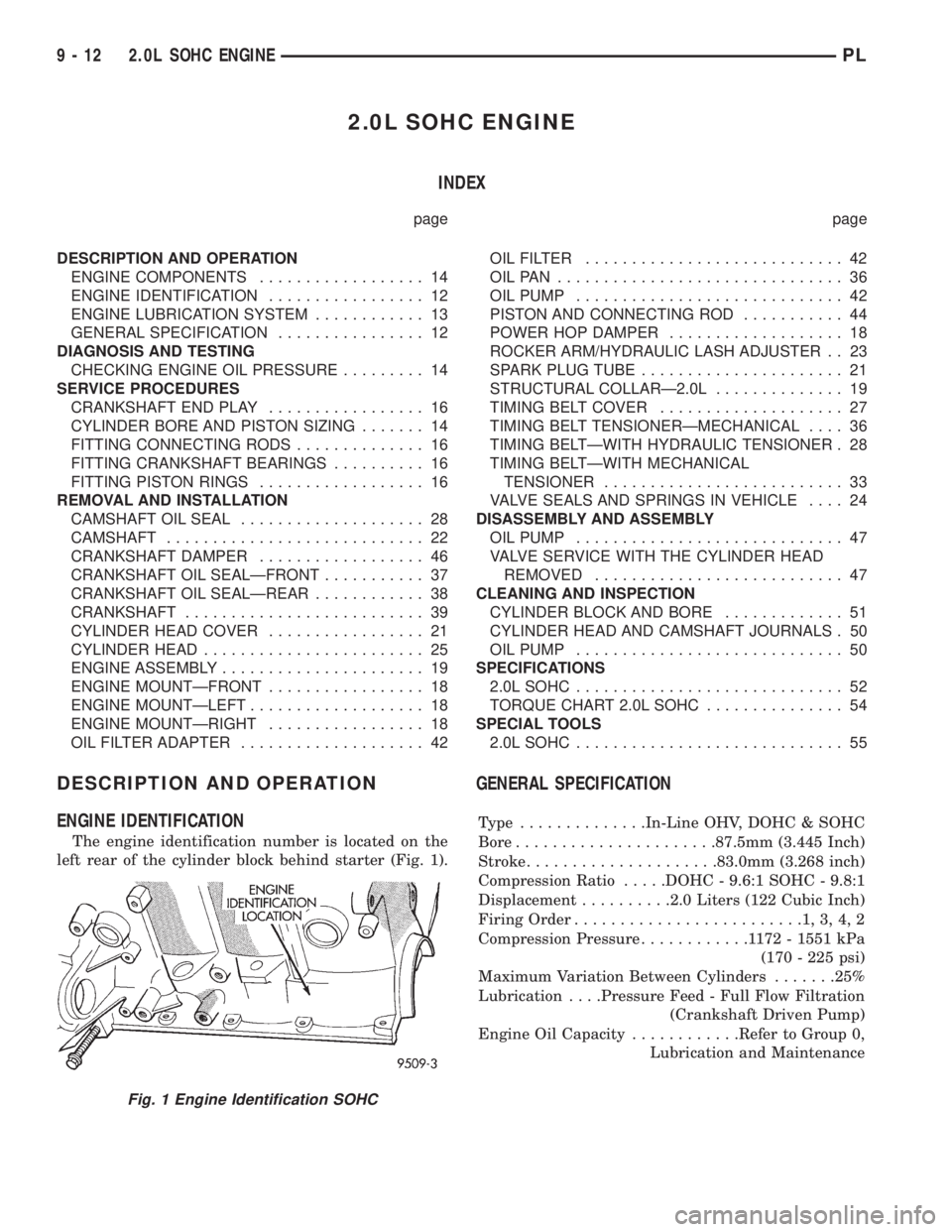
The engine identification number is located on the
left rear of the cylinder block behind starter (Fig. 1).
GENERAL SPECIFICATION
Type ..............In-Line OHV, DOHC & SOHC
Bore......................87.5mm (3.445 Inch)
Stroke.....................83.0mm (3.268 inch)
Compression Ratio.....DOHC - 9.6:1 SOHC - 9.8:1
Displacement..........2.0 Liters (122 Cubic Inch)
Firing Order.........................1,3,4,2
Compression Pressure............1172-1551 kPa
(170 - 225 psi)
Maximum Variation Between Cylinders.......25%
Lubrication. . . .Pressure Feed - Full Flow Filtration
(Crankshaft Driven Pump)
Engine Oil Capacity............Refer to Group 0,
Lubrication and Maintenance
Fig. 1 Engine Identification SOHC
9 - 12 2.0L SOHC ENGINEPL
Page 727 of 1200
MAIN/ROD BEARINGS
A diagonal hole in each bulkhead feeds oil to each
main bearing. Drilled passages within the crankshaft
route oil from main bearing journals to connecting
rod journals.
CAMSHAFT/HYDRAULIC LASH ADJUSTERS
A vertical hole at the number five bulkhead routes
pressurized oil through a restrictor up into the cylin-
der head. The rocker shafts route oil to the rocker
arms/hydraulic lash adjuster assemblies.
SPLASH LUBRICATION
Oil returning to the pan from pressurized compo-
nents supplies lubrication to the valve stems. Cylin-
der bores and wrist pins are splash lubricated from
directed slots on the connecting rod thrust collars.
ENGINE COMPONENTS
CYLINDER BLOCK AND BEDPLATE ASSEM-
B LY:A partial open deck is used for cooling and
weight reduction with water pump molded into the
block. Nominal wall thickness is 4 mm. The bedplate
incorporates main bearing caps. Rear seal retainer is
integral with the block.
CRANKSHAFT:A nodular cast iron crankshaft is
used. The engine has 5 main bearings, with number
3 flanged to control thrust. The 52 mm diameter
main and 48 mm diameter crank pin journals (all)
have undercut fillet radiuses that are deep rolled for
added strength. To optimize bearing loading 8 coun-
terweights are used. Hydrodynamic seals provide end
sealing, where the crankshaft exits the block.
Anaerobic gasket material is used for parting line
sealing. A sintered iron timing belt sprocket is
mounted on the crankshaft nose. This sprocket trans-
mits crankshaft movement, via timing belt to the
camshaft sprocket providing timed valve actuation.
PISTONS:The SOHC EngineDOES NOThave
provision for a free wheeling valve train. Non free
wheeling valve train means, in the event of a broken
timing belt Pistons will contact the Valves. All
engines use pressed-in piston pins to attach forged
powdered metal connecting rods. The connecting rods
are a cracked cap design and are not repairable. Hex
head cap screw are used to provide alignment and
durability in the assembly. Pistons And Connecting
rods are serviced as an assembly.
PISTON RINGS:The piston rings include a
molybdenum faced top ring for reliable compression
sealing and a taper faced intermediate ring for addi-
tional cylinder pressure control. Oil Control Ring
Package consist of 2 steel rails and a expander
spacer.
CYLINDER HEADÐSOHC:It features a Single
Over Head Camshaft, four-valves per cylinder cross
flow design. The valves are arranged in two inlinebanks, with the two intake per cylinder facing
toward the radiator. The exhaust valves facing
toward the dash panel. Rocker arm shafts mount
directly to the cylinder head. It incorporates powder
metal valve guides and seats. The hollow rocker arm
shafts supplies oil to the hydraulic lash adjusters,
camshaft and valve mechanisms.
CAMSHAFTÐSOHC:The nodular iron camshaft
has five bearing journals and 3 cam lobes per cylin-
der. Provision for cam position sensor on the cam at
the rear of cylinder head which also acts as thrust
plate. A hydrodynamic oil seal is used for oil control
at the front of the camshaft.
VALVESÐSOHC:Four valves per cylinder are
actuated by roller rocker arms/hydraulic lash adjust-
ers assemblies which pivot on rocker arm shafts. All
valves have 6 mm diameter chrome plated valve
stems. The valve train has 33 mm (1.299 inch) diam-
eter intake valves and 28 mm (1.10 inch) diameter
exhaust valves. Viton rubber valve stem seals are
integral with spring seats. Valve springs, spring
retainers, and locks are conventional design.
INTAKE MANIFOLD:The intake manifold is a
molded plastic composition, attached to the cylinder
head with ten fasteners. This long branch design
enhances low and mid-range torque.
EXHAUST MANIFOLD:The exhaust manifold is
made of nodular cast iron for strength and high tem-
peratures. Exhaust gasses exit through a machined,
articulated joint connection to the exhaust pipe.
DIAGNOSIS AND TESTING
CHECKING ENGINE OIL PRESSURE
(1) Remove oil pressure switch and install gauge
assembly C-3292 with adaptor.
(2) Run engine until thermostat opens.
CAUTION: If oil pressure is 0 at idle, Do Not per-
form the 3000 RPM test in the next step.
(3) Oil Pressure:Curb Idle25 kPa (4 psi) mini-
mum3000 RPM170-550 kPa (25-80 psi).
(4) If oil pressure is 0 at idle. Shut off engine,
check for pressure relief valve stuck open, a clogged
oil pick-up screen or a damaged oil pick-up tube
O-ring.
SERVICE PROCEDURES
CYLINDER BORE AND PISTON SIZING
The cylinder walls should be checked for out-of-
round and taper with Tool C-119 (Fig. 3). The cylin-
der bore out-of-round is 0.050 mm (.002 inch)
maximum and cylinder bore taper is 0.051 mm (0.002
9 - 14 2.0L SOHC ENGINEPL
DESCRIPTION AND OPERATION (Continued)
Page 758 of 1200
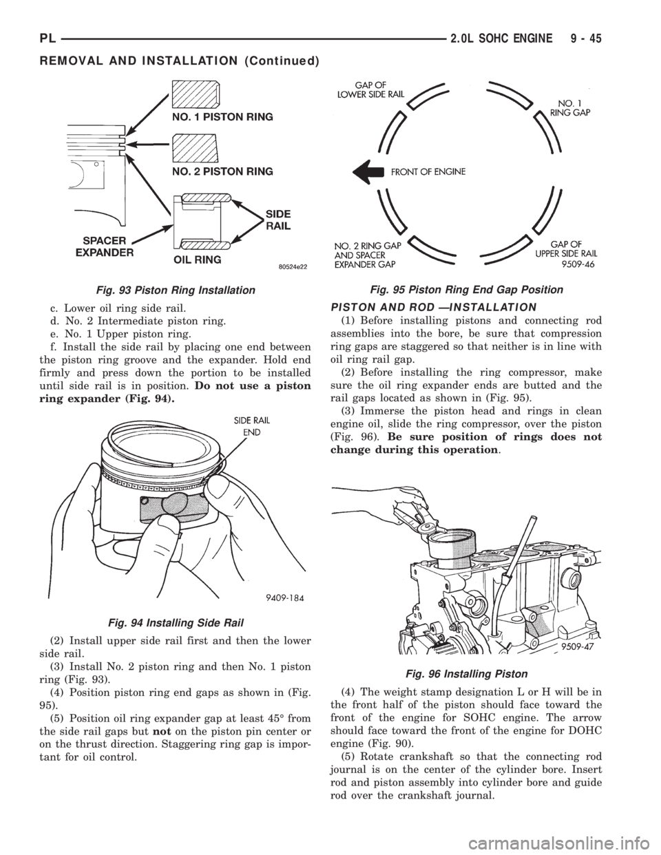
c. Lower oil ring side rail.
d. No. 2 Intermediate piston ring.
e. No. 1 Upper piston ring.
f. Install the side rail by placing one end between
the piston ring groove and the expander. Hold end
firmly and press down the portion to be installed
until side rail is in position.Do not use a piston
ring expander (Fig. 94).
(2) Install upper side rail first and then the lower
side rail.
(3) Install No. 2 piston ring and then No. 1 piston
ring (Fig. 93).
(4) Position piston ring end gaps as shown in (Fig.
95).
(5) Position oil ring expander gap at least 45É from
the side rail gaps butnoton the piston pin center or
on the thrust direction. Staggering ring gap is impor-
tant for oil control.PISTON AND ROD ÐINSTALLATION
(1) Before installing pistons and connecting rod
assemblies into the bore, be sure that compression
ring gaps are staggered so that neither is in line with
oil ring rail gap.
(2) Before installing the ring compressor, make
sure the oil ring expander ends are butted and the
rail gaps located as shown in (Fig. 95).
(3) Immerse the piston head and rings in clean
engine oil, slide the ring compressor, over the piston
(Fig. 96).Be sure position of rings does not
change during this operation.
(4) The weight stamp designation L or H will be in
the front half of the piston should face toward the
front of the engine for SOHC engine. The arrow
should face toward the front of the engine for DOHC
engine (Fig. 90).
(5) Rotate crankshaft so that the connecting rod
journal is on the center of the cylinder bore. Insert
rod and piston assembly into cylinder bore and guide
rod over the crankshaft journal.
Fig. 93 Piston Ring Installation
Fig. 94 Installing Side Rail
Fig. 95 Piston Ring End Gap Position
Fig. 96 Installing Piston
PL2.0L SOHC ENGINE 9 - 45
REMOVAL AND INSTALLATION (Continued)
Page 766 of 1200
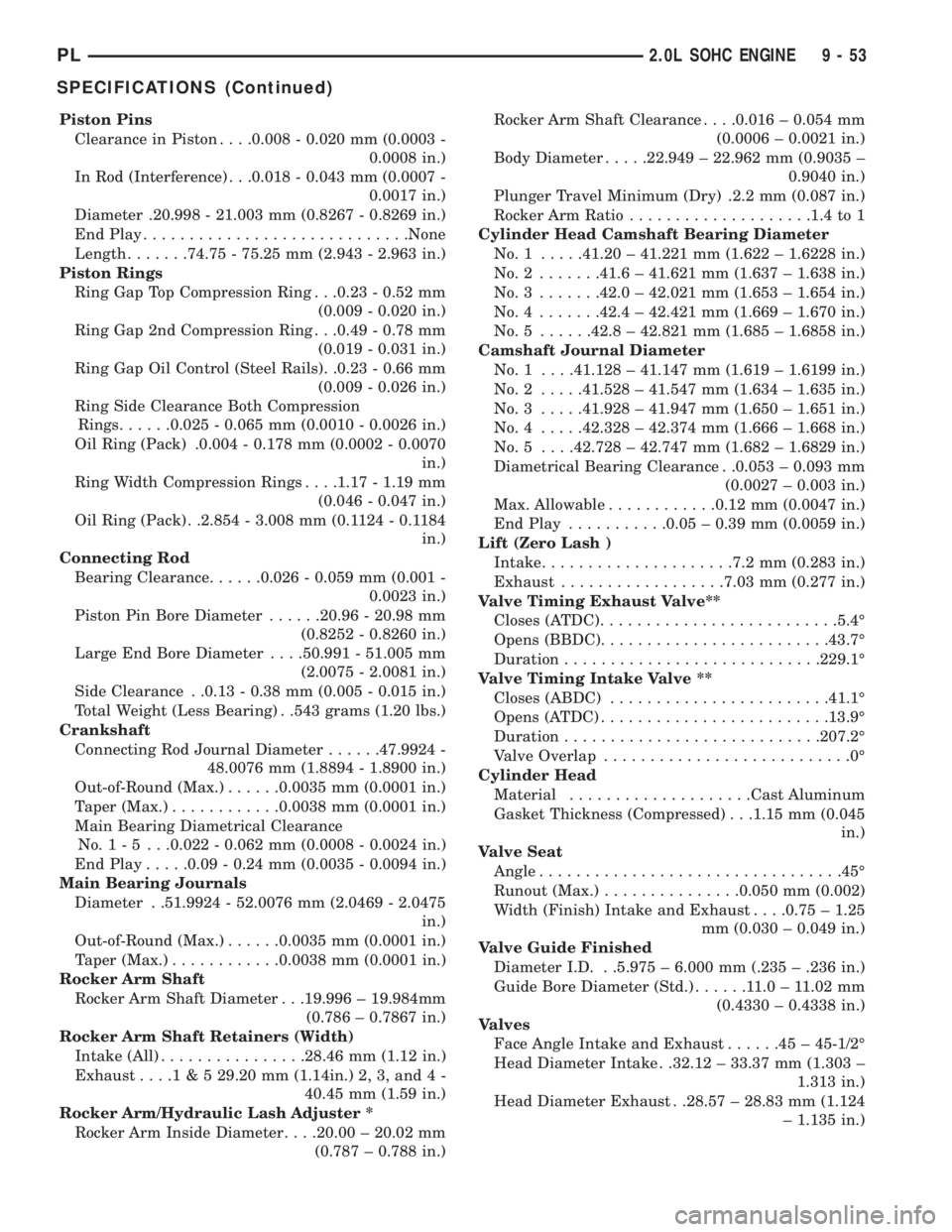
Piston Pins
Clearance in Piston. . . .0.008 - 0.020 mm (0.0003 -
0.0008 in.)
In Rod (Interference) . . .0.018 - 0.043 mm (0.0007 -
0.0017 in.)
Diameter .20.998 - 21.003 mm (0.8267 - 0.8269 in.)
End Play.............................None
Length.......74.75 - 75.25 mm (2.943 - 2.963 in.)
Piston Rings
Ring Gap Top Compression Ring . . .0.23 - 0.52 mm
(0.009 - 0.020 in.)
Ring Gap 2nd Compression Ring . . .0.49 - 0.78 mm
(0.019 - 0.031 in.)
Ring Gap Oil Control (Steel Rails). .0.23 - 0.66 mm
(0.009 - 0.026 in.)
Ring Side Clearance Both Compression
Rings......0.025 - 0.065 mm (0.0010 - 0.0026 in.)
Oil Ring (Pack) .0.004 - 0.178 mm (0.0002 - 0.0070
in.)
Ring Width Compression Rings. . . .1.17 - 1.19 mm
(0.046 - 0.047 in.)
Oil Ring (Pack) . .2.854 - 3.008 mm (0.1124 - 0.1184
in.)
Connecting Rod
Bearing Clearance......0.026 - 0.059 mm (0.001 -
0.0023 in.)
Piston Pin Bore Diameter......20.96 - 20.98 mm
(0.8252 - 0.8260 in.)
Large End Bore Diameter. . . .50.991 - 51.005 mm
(2.0075 - 2.0081 in.)
Side Clearance . .0.13 - 0.38 mm (0.005 - 0.015 in.)
Total Weight (Less Bearing) . .543 grams (1.20 lbs.)
Crankshaft
Connecting Rod Journal Diameter......47.9924 -
48.0076 mm (1.8894 - 1.8900 in.)
Out-of-Round (Max.)......0.0035 mm (0.0001 in.)
Taper (Max.)............0.0038 mm (0.0001 in.)
Main Bearing Diametrical Clearance
No.1-5 ...0.022 - 0.062 mm (0.0008 - 0.0024 in.)
End Play.....0.09 - 0.24 mm (0.0035 - 0.0094 in.)
Main Bearing Journals
Diameter . .51.9924 - 52.0076 mm (2.0469 - 2.0475
in.)
Out-of-Round (Max.)......0.0035 mm (0.0001 in.)
Taper (Max.)............0.0038 mm (0.0001 in.)
Rocker Arm Shaft
Rocker Arm Shaft Diameter . . .19.996 ± 19.984mm
(0.786 ± 0.7867 in.)
Rocker Arm Shaft Retainers (Width)
Intake (All)................28.46 mm (1.12 in.)
Exhaust....1 & 5 29.20 mm (1.14in.) 2, 3, and 4 -
40.45 mm (1.59 in.)
Rocker Arm/Hydraulic Lash Adjuster *
Rocker Arm Inside Diameter. . . .20.00 ± 20.02 mm
(0.787 ± 0.788 in.)Rocker Arm Shaft Clearance. . . .0.016 ± 0.054 mm
(0.0006 ± 0.0021 in.)
Body Diameter.....22.949 ± 22.962 mm (0.9035 ±
0.9040 in.)
Plunger Travel Minimum (Dry) .2.2 mm (0.087 in.)
Rocker Arm Ratio....................1.4 to 1
Cylinder Head Camshaft Bearing Diameter
No.1 .....41.20 ± 41.221 mm (1.622 ± 1.6228 in.)
No.2 .......41.6 ± 41.621 mm (1.637 ± 1.638 in.)
No.3 .......42.0 ± 42.021 mm (1.653 ± 1.654 in.)
No.4 .......42.4 ± 42.421 mm (1.669 ± 1.670 in.)
No.5 ......42.8 ± 42.821 mm (1.685 ± 1.6858 in.)
Camshaft Journal Diameter
No. 1 . . . .41.128 ± 41.147 mm (1.619 ± 1.6199 in.)
No.2 .....41.528 ± 41.547 mm (1.634 ± 1.635 in.)
No.3 .....41.928 ± 41.947 mm (1.650 ± 1.651 in.)
No.4 .....42.328 ± 42.374 mm (1.666 ± 1.668 in.)
No. 5 . . . .42.728 ± 42.747 mm (1.682 ± 1.6829 in.)
Diametrical Bearing Clearance . .0.053 ± 0.093 mm
(0.0027 ± 0.003 in.)
Max. Allowable............0.12 mm (0.0047 in.)
End Play...........0.05 ± 0.39 mm (0.0059 in.)
Lift (Zero Lash )
Intake.....................7.2 mm (0.283 in.)
Exhaust..................7.03 mm (0.277 in.)
Valve Timing Exhaust Valve**
Closes (ATDC)..........................5.4É
Opens (BBDC).........................43.7É
Duration............................229.1É
Valve Timing Intake Valve **
Closes (ABDC)........................41.1É
Opens (ATDC).........................13.9É
Duration............................207.2É
Valve Overlap...........................0É
Cylinder Head
Material....................Cast Aluminum
Gasket Thickness (Compressed) . . .1.15 mm (0.045
in.)
Valve Seat
Angle.................................45É
Runout (Max.)...............0.050 mm (0.002)
Width (Finish) Intake and Exhaust. . . .0.75 ± 1.25
mm (0.030 ± 0.049 in.)
Valve Guide Finished
Diameter I.D. . .5.975 ± 6.000 mm (.235 ± .236 in.)
Guide Bore Diameter (Std.)......11.0±11.02 mm
(0.4330 ± 0.4338 in.)
Valves
Face Angle Intake and Exhaust......45±45-1/2É
Head Diameter Intake . .32.12 ± 33.37 mm (1.303 ±
1.313 in.)
Head Diameter Exhaust . .28.57 ± 28.83 mm (1.124
± 1.135 in.)
PL2.0L SOHC ENGINE 9 - 53
SPECIFICATIONS (Continued)
Page 771 of 1200
2.0L DOHC ENGINE
INDEX
page page
DESCRIPTION AND OPERATION
ENGINE COMPONENTS.................. 59
ENGINE IDENTIFICATION NUMBER......... 58
ENGINE LUBRICATION SYSTEM............ 58
GENERAL SPECIFICATION................ 58
DIAGNOSIS AND TESTING
CHECKING ENGINE OIL PRESSURE......... 60
SERVICE PROCEDURES
CRANKSHAFT END PLAY................. 63
CYLINDER BORE AND PISTON SIZING....... 60
FITTING CONNECTING RODS.............. 62
FITTING CRANKSHAFT BEARINGS.......... 62
FITTING PISTON RINGS.................. 61
REMOVAL AND INSTALLATION
CAMSHAFT OIL SEALS................... 81
CAM FOLLOWER AND HYDRAULIC LASH
ADJUSTER ASSEMBLY.................. 69
CAMSHAFT............................ 67
CRANKSHAFT DAMPER.................. 73
CRANKSHAFT OIL SEALÐFRONT........... 82
CRANKSHAFT OIL SEALÐREAR............ 83
CRANKSHAFT.......................... 85
CYLINDER HEAD COVER................. 67
CYLINDER HEAD........................ 71
ENGINE ASSEMBLY...................... 65
ENGINE MOUNTÐFRONT................. 63
ENGINE MOUNTÐLEFT................... 63
ENGINE MOUNTÐRIGHT................. 64OIL FILTER ADAPTER.................... 87
OILFILTER ............................ 87
OILPAN ............................... 81
OIL PUMP............................. 88
PISTON AND CONNECTING ROD........... 89
POWER HOP DAMPER................... 64
STRUCTURAL COLLARÐ2.0L.............. 64
TIMING BELT COVER.................... 74
TIMING BELT TENSIONERÐMECHANICAL.... 80
TIMING BELTÐWITH HYDRAULIC TENSIONER . 75
TIMING BELTÐWITH MECHANICAL
TENSIONER.......................... 78
VALVE SPRING AND SEALSÐ
CYLINDER HEAD NOT REMOVED......... 69
DISASSEMBLY AND ASSEMBLY
OIL PUMP............................. 91
VALVE SERVICE WITH CYLINDER HEAD
REMOVED........................... 91
CLEANING AND INSPECTION
CYLINDER BLOCK AND BORE............. 96
CYLINDER HEAD AND CAMSHAFT JOURNALS . 94
OIL PUMP............................. 94
SPECIFICATIONS
2.0L DOHC............................. 96
TORQUE CHART 2.0L DOHC............... 98
SPECIAL TOOLS
2.0L DOHC............................. 98
DESCRIPTION AND OPERATION
ENGINE IDENTIFICATION NUMBER
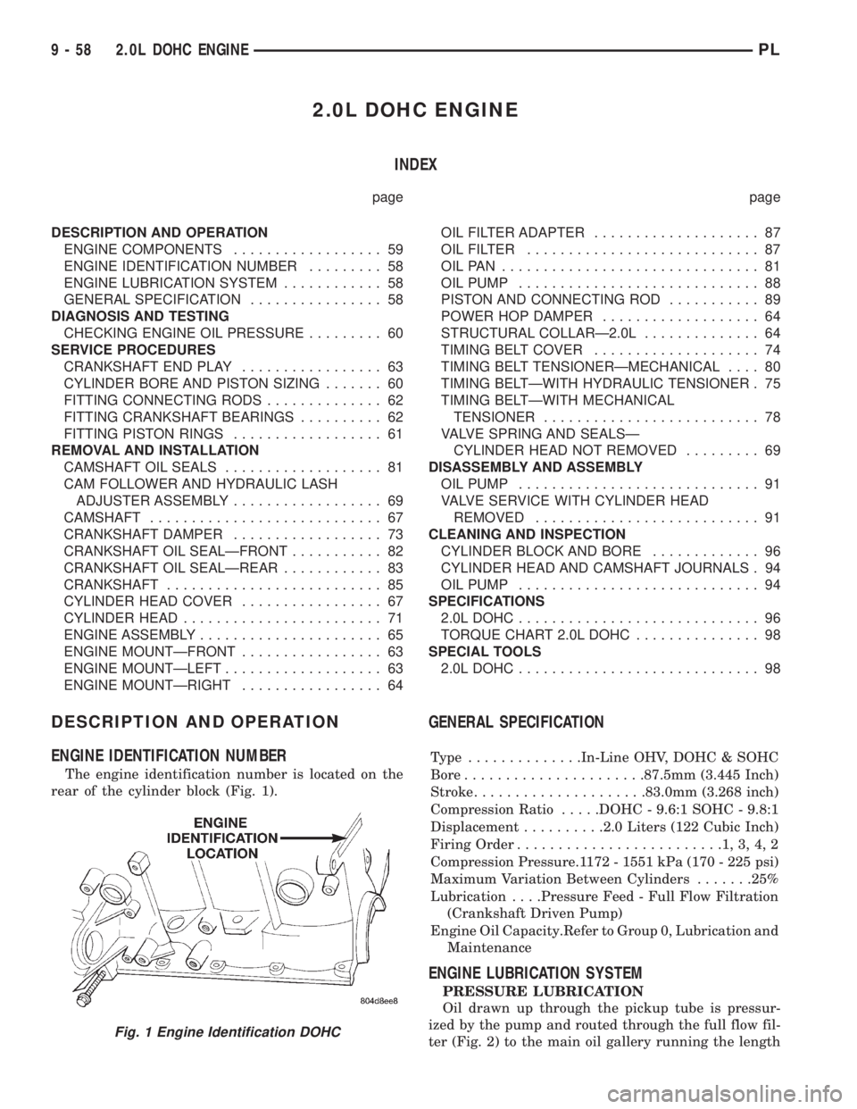
The engine identification number is located on the
rear of the cylinder block (Fig. 1).
GENERAL SPECIFICATION
Type ..............In-Line OHV, DOHC & SOHC
Bore......................87.5mm (3.445 Inch)
Stroke.....................83.0mm (3.268 inch)
Compression Ratio.....DOHC - 9.6:1 SOHC - 9.8:1
Displacement..........2.0 Liters (122 Cubic Inch)
Firing Order.........................1,3,4,2
Compression Pressure.1172 - 1551 kPa (170 - 225 psi)
Maximum Variation Between Cylinders.......25%
Lubrication. . . .Pressure Feed - Full Flow Filtration
(Crankshaft Driven Pump)
Engine Oil Capacity.Refer to Group 0, Lubrication and
Maintenance
ENGINE LUBRICATION SYSTEM
PRESSURE LUBRICATION
Oil drawn up through the pickup tube is pressur-
ized by the pump and routed through the full flow fil-
ter (Fig. 2) to the main oil gallery running the length
Fig. 1 Engine Identification DOHC
9 - 58 2.0L DOHC ENGINEPL