1999 DODGE NEON compression ratio
[x] Cancel search: compression ratioPage 773 of 1200
incorporates main bearing caps. Rear seal retainer is
integral with the block.
CRANKSHAFTA nodular cast iron crankshaft is
used. The engine has 5 main bearings, with number
3 flanged to control thrust. The 52 mm diameter
main and 48 mm diameter crank pin journals (all)
have undercut fillet radiuses that are deep rolled for
added strength. To optimize bearing loading 8 coun-
terweights are used. Hydrodynamic seals provide end
sealing, where the crankshaft exits the block.
Anaerobic gasket material is used for parting line
sealing. A sintered iron timing belt sprocket is
mounted on the crankshaft nose. This sprocket pro-
vides motive power; via timing belt to the camshaft
sprocket providing timed valve actuation.
PISTONSThe DOHC EngineDO NOThave pro-
vision for a free wheeling valve train. Non free
wheeling valve train means, in the event of a broken
timing belt Pistons will contact the Valves. All
engines use pressed-in piston pins to attach forged
powdered metal connecting rods. The connecting rods
are a cracked cap design and are not repairable. Hex
head cap screw are used to provide alignment and
durability in the assembly.
PISTON RINGSThe piston rings include a
molybdenum faced top ring for reliable compression
sealing and a taper faced intermediate ring for addi-
tional cylinder pressure control. Oil Control Ring
Package contains of 2 steel rails and a expander
spacer.
CYLINDER HEADFeatures a Dual Over Head
Camshaft (DOHC), 4 valves per cylinder cross flow
design. The valves are arranged in two in-line banks,
with the ports of the bank of two intake valves per
cylinder facing toward the radiator side of engine
and ports of the bank of two exhaust valves per cyl-
inder facing toward the dash panel. Incorporates
powder metal valve guides and seats. Integral oil gal-
leys within the cylinder head supplies oil to the
hydraulic lash adjusters, camshaft and valve mecha-
nisms.
CAMSHAFTSThe nodular iron camshafts have
six bearing journals and 2 cam lobes per cylinder.
Flanges at the rear journals control camshaft end
play. Provision for cam position sensor is located on
the intake camshaft at the rear of cylinder head. A
hydrodynamic oil seal is used for oil control at the
front of the camshaft.
VA LV E SFour valves per cylinder are actuated by
roller cam followers which pivot on stationary
hydraulic lash adjusters. All valves have 6 mm diam-
eter chrome plated valve stems. The valve sizes are
34.8 mm (1.370 inch.) diameter intake valves and
30.5 mm (1.20 inch.) diameter exhaust valves. Viton
rubber valve stem seals are integral with the springseats. Valve springs, spring retainers, and locks are
conventional.
INTAKE MANIFOLDThe intake manifold is a
two piece aluminum casting, attached to the cylinder
head with ten fasteners. This long branch fan design
enhances low and mid-speed torque.
EXHAUST MANIFOLDThe exhaust manifold is
made of nodular cast iron for strength and high tem-
peratures. Exhaust gasses exit through a machined,
articulated joint connection to the exhaust pipe.
COMPONENT REPLACEMENT
If any of the following parts have been changed or
replaced:
²Camshaft
²Camshaft Position Sensor
²Camshaft Position Sensor Target Magnet
²Cylinder Block
²Cylinder Head
²Water Pump
²Powertrain Control Module (PCM)
²Timing Belt and Timing Belt Tensioner
The camshaft and crankshaft timing relearn proce-
dure must be performed. Refer to the component
Removal and Installation procedure outlined in this
Group.
DIAGNOSIS AND TESTING
CHECKING ENGINE OIL PRESSURE
(1) Remove oil pressure switch and install gauge
assembly C-3292 with adaptor.
(2) Run engine until thermostat opens.
CAUTION: If oil pressure is 0 at idle, Do Not per-
form the 3000 RPM test in the next step.
(3) Oil Pressure:Curb Idle25 kPa (4 psi) mini-
mum3000 RPM170-550 kPa (25-80 psi).
(4) If oil pressure is 0 at idle. Shut off engine,
check for pressure relief valve stuck open, a clogged
oil pick-up screen or a damaged oil pick-up tube
O-ring.
SERVICE PROCEDURES
CYLINDER BORE AND PISTON SIZING
The cylinder walls should be checked for out-of-
round and taper with Tool C-119 (Fig. 4). The cylin-
der bore out-of-round is 0.050 mm (.002 inch)
maximum and cylinder bore taper is 0.051 mm (0.002
inch) maximum. If the cylinder walls are badly
scuffed or scored, the cylinder block should be
rebored and honed, and new pistons and rings fitted.
Whatever type of boring equipment is used, boring
and honing operation should be closely coordinated
9 - 60 2.0L DOHC ENGINEPL
DESCRIPTION AND OPERATION (Continued)
Page 810 of 1200
Piston Ring Groove Depth No. 2 .4.456 - 4.605 mm
(0.175 - 0.181 in.)
Piston Ring Groove Depth No. 3 .3.841 - 4.075 mm
(0.151 - 0.160 in.)
Piston Pins
Clearance in Piston. . . .0.008 - 0.020 mm (0.0003 -
0.0008 in.)
In Rod (Interference) . . .0.018 - 0.043 mm (0.0007 -
0.0017 in.)
Diameter .20.998 - 21.003 mm (0.8267 - 0.8269 in.)
End Play.............................None
Length.......74.75 - 75.25 mm (2.943 - 2.963 in.)
Piston Rings
Ring Gap Top Compression Ring . . .0.23 - 0.52 mm
(0.009 - 0.020 in.)
Ring Gap 2nd Compression Ring . . .0.49 - 0.78 mm
(0.019 - 0.031 in.)
Ring Gap Oil Control (Steel Rails). .0.23 - 0.66 mm
(0.009 - 0.026 in.)
Ring Side Clearance Both
Compression Rings. . . .0.025 - 0.065 mm (0.0010 -
0.0026 in.)
Oil Ring (Pack).0.004 - 0.178 mm (0.0002 - 0.0070 in.)
Ring Width Compression Rings. . . .1.17 - 1.19 mm
(0.046 - 0.047 in.)
Oil Ring (Pack).2.854 - 3.008 mm (0.1124 - 0.1184 in.)
Connecting Rod
Bearing Clearance.0.026 - 0.059 mm (0.001 - 0.0023
in.)
Piston Pin Bore Diameter.20.96 - 20.98 mm (0.8252
- 0.8260 in.)
Large End Bore Diameter. . . .50.991 - 51.005 mm
(2.0075 - 2.0081 in.)
Side Clearance . .0.13 - 0.38 mm (0.005 - 0.015 in.)
Total Weight (Less Bearing) . .543 grams (1.20 lbs.)
Crankshaft
Connecting Rod Journal Diameter.47.9924 - 48.0076
mm (1.8894 - 1.8900 in.)
Out-of-Round (Max.)......0.0035 mm (0.0001 in.)
Taper (Max.)............0.0038 mm (0.0001 in.)
Main Bearing Diametrical
Clearance No. 1 - 5.0.022 - 0.062 mm (0.0008 - 0.0024
in.)
End Play.....0.09 - 0.24 mm (0.0035 - 0.0094 in.)
Main Bearing Journals
Diameter.51.9924 - 52.0076 mm (2.0469 - 2.0475 in.)
Out-of-Round (Max.)......0.0035 mm (0.0001 in.)
Taper (Max.)............0.0038 mm (0.0001 in.)
Camshaft
Bearing Bore Diameter No. 1 - 6.26.020 mm - 26.041
mm (1.024 - 1.025 in.)
Diametrical Bearing Clearance . .0.069 - 0.071 mm
(0.0027 - 0.003 in.)
End Play.......0.05 - 0.15 mm (0.002 - 0.006 in.)Bearing Journal Diameter No. 1 - 6.25.951 - 25.970
mm (1.021 - 1.022 in.)
Lift (Zero Lash) Intake.......8.75 mm (0.344 in.)
Lift (Zero Lash) Exhaust.....8.00 mm (0.314 in.)
Valve Timing @ .5 mm Lift
Intake Valve Closes (ABDC)...............38É
Intake Valve Opens (BTDC)...............1.2É
Intake Valve Duration..................219.2É
Exhaust Valve Closes (BTDC)...............3É
Exhaust Valve Opens (BBDC)..............42É
Exhaust Valve Duration..................219É
Valve Overlap...........................0É
Cylinder Head
Material.....................Cast Aluminum
Gasket Thickness (Compressed).1.15 mm (0.045 in.)
Valve Seat Angle...................44.5 - 45É
Runout (Max.).............0.050 mm (0.002 in.)
Width (Finished) Intake and Exhaust .0.9 - 1.3 mm
(0.035 - 0.051 in.)
Valve Guide Finished Diameter ID.5.975 - 6.000 mm
(0.235 - 0.236 in.)
Guide Bore Diameter (Standard) . .11.0 - 11.02 mm
(0.4330 - 0.4338 in.)
Valves
Head Diameter Intake . .34.67 - 34.93 mm (1.365 -
1.375 in.)
Head Diameter Exhaust .30.37 - 30.36 mm (1.195 -
1.195 in.)
Valve Margin Intake.1.15 - 1.48 mm (0.0452 - 0.0582
in.)
Valve Margin Exhaust . .1.475 - 1.805 mm (0.058 -
0.071 in.)
Length Intake.111.49 -111.99 mm (4.389 - 4.409 in.)
Length Exhaust .109.59 - 110.09 mm (4.314 - 4.334
in.)
Valve Stem Tip Heigth Intake.48.04 mm (1.891 in.)
Valve Stem Tip Heigth Exhaust.47.99 mm (1.889 in.)
Stem Diameter Intake. .5.9034 - 5.952 mm (0.234 -
0.234 in.)
Stem Diameter Exhaust .5.906 - 5.924 mm (0.233 -
0.233 in.)
Stem-to-Guide Clearance Intake .0.023 - 0.066 mm
(0.0009 - 0.0025 in.)
Stem-to-Guide Clearance Exhaust.0.051 - 0.094 mm
(0.002 - 0.0037 in.)
Maximum Allowable Intake . .0.076 mm (0.003 in.)
Maximum Allowable Exhaust .0.101 mm (0.004 in.)
Valve Spring
Free Length (Approx.).........46mm(1.811 in.)
Spring Tension (Valve Closed).246 - 270 N @ 38.0 mm
(55 - 60 lbs. @ 1.496 in.)
Spring Tension (Valve Open).549 - 611 N @ 29.3 mm
(123 - 137 lbs. @ 1.53 in.)
PL2.0L DOHC ENGINE 9 - 97
SPECIFICATIONS (Continued)
Page 814 of 1200
ENGINE
CONTENTS
page
1.8L SOHC ENGINE...................... 1
1.8L SOHC ENGINE
INDEX
page
GENERAL INFORMATION
1.8L SOHC ENGINE...................... 1
GENERAL INFORMATION
1.8L SOHC ENGINE
For service of the 1.8L SOHC engine refer to the
2.0L SOHC engine information except for the follow-
ing specifications.
GENERAL SPECIFICATIONS
Type .....................In-Line OHV, SOHC
Bore..............................83.0 mm
Stroke.............................83.0mm
Compression Ratio.....................10.0:1
Displacement......................1.8Liters
Firing Order........................1,3,4,2
Compression (Cranking)
Pressure.......1172-1551 kPa (170 - 225 psi)
Maximum Variation Between Cylinders......25%
Lubrication . . . Pressure Feed - Full Flow Filtration
(Crankshaft Driven Pump)
CYLINDER BORE AND PISTON
SPECIFICATIONS CHART
Standard Bore Maximum
Out-of-RoundMaximum
Taper
82.993 - 83.007
mm0.051 mm 0.051 mm
Standard Piston Size
82.974 - 82.956 mm
Piston to Bore Clearance
0.018 - 0.050 mm
Measurements Taken at Piston Size Location
PISTON RING SPECIFICATIONS
Ring Position Ring Gap Wear Limit
Upper Ring 0.23 - 0.38 mm 0.8 mm
Intermediate
Ring0.20 - 0.47 mm 1.0 mm
Oil Control Ring 0.25 -0.64 mm 1.0 mm
Ring Position Groove
ClearanceMaximum
Clearance
Upper Ring 0.03 - 0.07 mm 0.10 mm
Intermediate
Ring0.040 - 0.078
mm0.10 mm
OIL CONTROL RING (THREE PIECE) - OIL RING
SIDE RAILS MUST BE FREE TO ROTATE AFTER
ASSEMBLY
PLENGINE 9 - 1
Page 875 of 1200
FUEL INJECTORSÐPCM OUTPUT
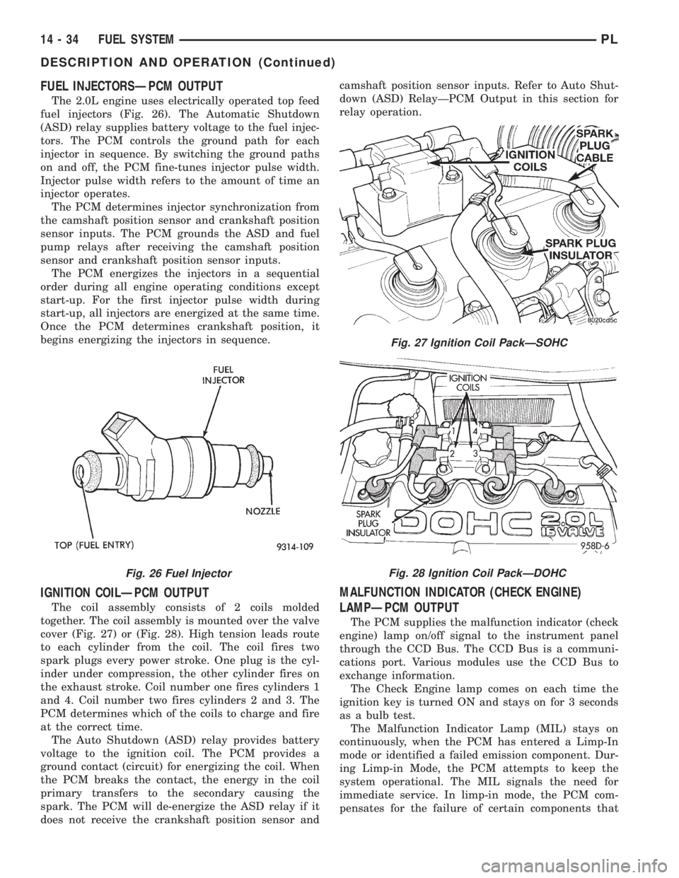
The 2.0L engine uses electrically operated top feed
fuel injectors (Fig. 26). The Automatic Shutdown
(ASD) relay supplies battery voltage to the fuel injec-
tors. The PCM controls the ground path for each
injector in sequence. By switching the ground paths
on and off, the PCM fine-tunes injector pulse width.
Injector pulse width refers to the amount of time an
injector operates.
The PCM determines injector synchronization from
the camshaft position sensor and crankshaft position
sensor inputs. The PCM grounds the ASD and fuel
pump relays after receiving the camshaft position
sensor and crankshaft position sensor inputs.
The PCM energizes the injectors in a sequential
order during all engine operating conditions except
start-up. For the first injector pulse width during
start-up, all injectors are energized at the same time.
Once the PCM determines crankshaft position, it
begins energizing the injectors in sequence.
IGNITION COILÐPCM OUTPUT
The coil assembly consists of 2 coils molded
together. The coil assembly is mounted over the valve
cover (Fig. 27) or (Fig. 28). High tension leads route
to each cylinder from the coil. The coil fires two
spark plugs every power stroke. One plug is the cyl-
inder under compression, the other cylinder fires on
the exhaust stroke. Coil number one fires cylinders 1
and 4. Coil number two fires cylinders 2 and 3. The
PCM determines which of the coils to charge and fire
at the correct time.
The Auto Shutdown (ASD) relay provides battery
voltage to the ignition coil. The PCM provides a
ground contact (circuit) for energizing the coil. When
the PCM breaks the contact, the energy in the coil
primary transfers to the secondary causing the
spark. The PCM will de-energize the ASD relay if it
does not receive the crankshaft position sensor andcamshaft position sensor inputs. Refer to Auto Shut-
down (ASD) RelayÐPCM Output in this section for
relay operation.
MALFUNCTION INDICATOR (CHECK ENGINE)
LAMPÐPCM OUTPUT
The PCM supplies the malfunction indicator (check
engine) lamp on/off signal to the instrument panel
through the CCD Bus. The CCD Bus is a communi-
cations port. Various modules use the CCD Bus to
exchange information.
The Check Engine lamp comes on each time the
ignition key is turned ON and stays on for 3 seconds
as a bulb test.
The Malfunction Indicator Lamp (MIL) stays on
continuously, when the PCM has entered a Limp-In
mode or identified a failed emission component. Dur-
ing Limp-in Mode, the PCM attempts to keep the
system operational. The MIL signals the need for
immediate service. In limp-in mode, the PCM com-
pensates for the failure of certain components that
Fig. 26 Fuel Injector
Fig. 27 Ignition Coil PackÐSOHC
Fig. 28 Ignition Coil PackÐDOHC
14 - 34 FUEL SYSTEMPL
DESCRIPTION AND OPERATION (Continued)
Page 1173 of 1200
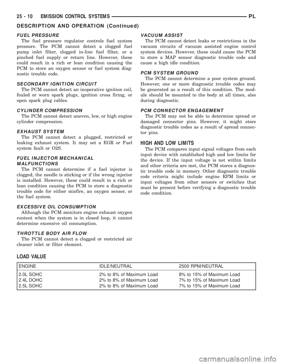
FUEL PRESSURE
The fuel pressure regulator controls fuel system
pressure. The PCM cannot detect a clogged fuel
pump inlet filter, clogged in-line fuel filter, or a
pinched fuel supply or return line. However, these
could result in a rich or lean condition causing the
PCM to store an oxygen sensor or fuel system diag-
nostic trouble code.
SECONDARY IGNITION CIRCUIT
The PCM cannot detect an inoperative ignition coil,
fouled or worn spark plugs, ignition cross firing, or
open spark plug cables.
CYLINDER COMPRESSION
The PCM cannot detect uneven, low, or high engine
cylinder compression.
EXHAUST SYSTEM
The PCM cannot detect a plugged, restricted or
leaking exhaust system. It may set a EGR or Fuel
system fault or O2S.
FUEL INJECTOR MECHANICAL
MALFUNCTIONS
The PCM cannot determine if a fuel injector is
clogged, the needle is sticking or if the wrong injector
is installed. However, these could result in a rich or
lean condition causing the PCM to store a diagnostic
trouble code for either misfire, an oxygen sensor, or
the fuel system.
EXCESSIVE OIL CONSUMPTION
Although the PCM monitors engine exhaust oxygen
content when the system is in closed loop, it cannot
determine excessive oil consumption.
THROTTLE BODY AIR FLOW
The PCM cannot detect a clogged or restricted air
cleaner inlet or filter element.
VACUUM ASSIST
The PCM cannot detect leaks or restrictions in the
vacuum circuits of vacuum assisted engine control
system devices. However, these could cause the PCM
to store a MAP sensor diagnostic trouble code and
cause a high idle condition.
PCM SYSTEM GROUND
The PCM cannot determine a poor system ground.
However, one or more diagnostic trouble codes may
be generated as a result of this condition. The mod-
ule should be mounted to the body at all times, also
during diagnostic.
PCM CONNECTOR ENGAGEMENT
The PCM may not be able to determine spread or
damaged connector pins. However, it might store
diagnostic trouble codes as a result of spread connec-
tor pins.
HIGH AND LOW LIMITS
The PCM compares input signal voltages from each
input device with established high and low limits for
the device. If the input voltage is not within limits
and other criteria are met, the PCM stores a diagnos-
tic trouble code in memory. Other diagnostic trouble
code criteria might include engine RPM limits or
input voltages from other sensors or switches that
must be present before verifying a diagnostic trouble
code condition.
LOAD VALUE
ENGINE IDLE/NEUTRAL 2500 RPM/NEUTRAL
2.0L SOHC 2% to 8% of Maximum Load 8% to 15% of Maximum Load
2.4L DOHC 2% to 8% of Maximum Load 7% to 15% of Maximum Load
2.5L SOHC 2% to 8% of Maximum Load 7% to 15% of Maximum Load
25 - 10 EMISSION CONTROL SYSTEMSPL
DESCRIPTION AND OPERATION (Continued)