1999 DODGE NEON check engine light
[x] Cancel search: check engine lightPage 4 of 1200
MAINTENANCE SCHEDULES
INDEX
page page
GENERAL INFORMATION
INTRODUCTION......................... 3
SCHEDULE ± A.......................... 3SCHEDULE ± B.......................... 4
UNSCHEDULED INSPECTION............... 3
GENERAL INFORMATION
INTRODUCTION
Service and maintenance procedures for compo-
nents and systems listed in Schedule ± A or B can be
found by using the Group Tab Locator index at the
front of this manual. If it is not clear which group
contains the information needed, refer to the index at
the back of this manual.
There are two maintenance schedules that show
proper service based on the conditions that the vehi-
cle is subjected to. Use the schedule that best
describes these conditions.
Schedule ±A, lists maintenance recommended for
vehicles used for general transportation.
Schedule ±B, lists maintenance recommended for
vehicles used under the following conditions:
²Frequent short trip driving less than 5 miles (8
km)
²Frequent driving in dusty conditions
²Frequent trailer towing
²Extensive idling
²More than 50% of your driving is at sustained
high speeds during hot weather, above 90ÉF (32ÉC)
Where time and mileage are listed, follow the
interval that occurs first.
EMISSION CONTROL SYSTEM MAINTENANCE
The scheduled emission maintenance listed inbold
typeon the Maintenance Schedules, must be done at
the mileage specified to assure the continued proper
functioning of the emission control system. These,
and all other maintenance services included in this
manual, should be done to provide the best vehicle
performance and reliability. More frequent mainte-
nance may be needed for vehicles in severe operating
conditions such as dusty areas and very short trip
driving.
UNSCHEDULED INSPECTION
At Each Stop For Fuel
²Check engine oil level, add as required.
²Check windshield washer solvent and add if
required.
Once A Month
²Check tire pressure and look for unusual wear
or damage.
²Inspect battery, clean, and tighten terminals as
required.
²Check fluid levels of coolant reservoir, power
steering and automatic transmission and add as
required.
²Check all lights and all other electrical items for
correct operation.
At Each Oil Change
²Inspect exhaust system.
²Inspect brake hoses.
²Inspect the CV joints and front suspension com-
ponents.
²Rotate the tires at each oil change interval
shown on Schedule ± A (7,500 miles) or every other
interval shown on schedule ± B (6,000 miles).
²Check coolant level, hoses and clamps.
²Check the manual transaxle fluid level.
²If the mileage is less than 7,500 miles (12 000
km) yearly, replace the engine oil filter at each oil
change.
SCHEDULE ± A
7,500 Miles (12 000 km) or at 6 months
²Change engine oil.
15,000 Miles (24 000 km) or at 12 months
²Change engine oil.
²Replace engine oil filter.
²Adjust drive belt tension.
22,500 Miles (36 000 km) or at 18 months
²Change engine oil.
²Inspect the front brake pads and rear brake lin-
ings.
30,000 Miles (48 000 km) or at 24 months
²Change engine oil.
²Replace engine oil filter.
²Lubricate front suspension ball joints.
²Adjust drive belt tension.
PLLUBRICATION AND MAINTENANCE 0 - 3
Page 174 of 1200
CLUTCH PEDAL POSITION
SWITCH±MECHANICAL TEST
With the park brake set and the vehicleIN NEU-
TRAL,turn the key to the start position. The vehicle
should not crank. If the vehicle cranks, the switch is
defective (shorted out) and must be replaced. If the
vehicle does not crank, proceed to the next step.
WARNING: BEFORE PERFORMING THIS STEP, BE
SURE THAT THE AREA IN FRONT OF THE VEHICLE
IS CLEAR OF OBSTRUCTIONS AND PEOPLE. VEHI-
CLE MAY MOVE WHEN PERFORMING THIS TEST.
With the park brake set and the vehicleIN GEAR,
turn the key to the start position and hold it there.
Slowly depress the clutch pedal and feel for any
vehicle motion when the starter is energized. If there
is no motion, the switch is working properly.
If motion is felt, check to see if the switch is mak-
ing contact when the pedal is between 25 mm (1.0
in.) and 6 mm (0.25 in.) from the floor. If this condi-
tion is met, then the problem is either the clutch orthe self-adjusting cable (See ªClutch Will Not Disen-
gage Properlyº). If this condition is not met, then the
switch mounting tab on the brake bracket is bent,
and the brake bracket must be replaced.
If vehicle will not crank, even with clutch pedal
pressed to the floor, refer to ªService Diagnosis-
Clutch Pedal Position Switchº chart in this section.
CLUTCH DIAGNOSIS
Problem diagnosis will generally require a road
test to determine the type of fault. Component
inspection will then determine the problem after road
testing.
Drive the vehicle at normal speeds during road
test. Shift the transaxle through all gear ranges and
observe clutch action. If chatter, grab, slip, or
improper release is experienced, remove and inspect
the clutch components. If the problem is noise or
hard shifting, further diagnosis may be needed. The
transaxle or other driveline components may actually
be at fault.
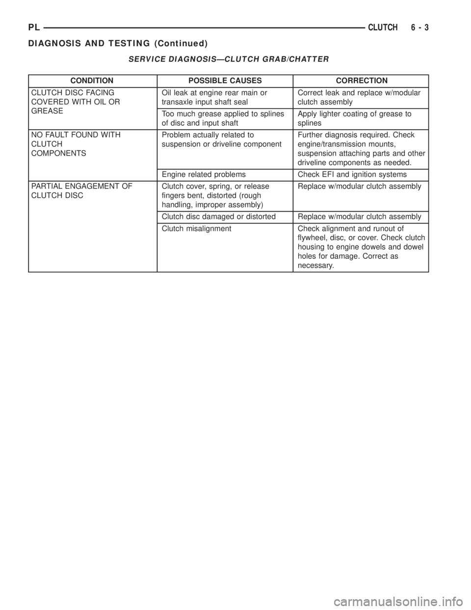
SERVICE DIAGNOSISÐCLUTCH GRAB/CHATTER
CONDITION POSSIBLE CAUSES CORRECTION
CLUTCH DISC FACING
COVERED WITH OIL OR
GREASEOil leak at engine rear main or
transaxle input shaft sealCorrect leak and replace w/modular clutch
assembly
Too much grease applied to splines
of disc and input shaftApply lighter coating of grease to splines
NO FAULT FOUND WITH
CLUTCH
COMPONENTSProblem actually related to
suspension or driveline componentFurther diagnosis required. Check
engine/transmission mounts, suspension
attaching parts and other driveline
components as needed.
Engine related problems Check EFI and ignition systems
PARTIAL ENGAGEMENT
OF CLUTCH DISCClutch cover, spring, or release
fingers bent, distorted (rough
handling, improper assembly)Replace w/modular clutch assembly
Clutch disc damaged or distorted Replace w/modular clutch assembly
Clutch misalignment Check alignment and runout of flywheel,
disc, or cover. Check clutch housing to
engine dowels and dowel holes for damage.
Correct as necessary.
PLCLUTCH 6 - 3
DIAGNOSIS AND TESTING (Continued)
Page 177 of 1200
DRIVE PLATE MISALIGNMENT
Common causes of misalignment are:
²Heat warping
²Mounting drive plate on a dirty crankshaft
flange
²Incorrect bolt tightening
²Improper seating on the crankshaft shoulder
²Loose crankshaft bolts
Clean the crankshaft flange before mounting the
drive plate. Dirt and grease on the flange surface
may misalign the flywheel, causing excessive runout.
Use new bolts when mounting drive plate to crank-
shaft. Tighten drive plate bolts to specified torque
only. Over-tightening can distort the drive plate hub
causing excessive runout.
CLUTCH COVER AND DISC RUNOUT
Check condition of the clutch cover before installa-
tion. A warped cover or diaphragm spring will cause
grab and/or incomplete release or engagement. Use
care when handling the clutch assembly. Impact can
distort the cover, diaphragm spring, and release fin-
gers.
CLUTCH CHATTER COMPLAINTS
For all clutch chatter complaints, do the following:
(1) Check for loose, misaligned, or broken engine
and transmission mounts. If present, they should be
corrected at this time. Test vehicle for chatter. If
chatter is gone, there is no need to go any further. If
chatter persists:
(2) Check to see if clutch cable routing is correct
and operates smoothly.
(3) Check for loose connections in drive train. Cor-
rect any problems and determine if clutch chatter
complaints have been satisfied. If not:
(4) Remove transaxle. See Group 21, Manual Tran-
saxle for procedure.
(5) Check to see if the release bearing is sticky or
binding. Replace bearing, if needed.
(6) Check linkage for excessive wear on the pivot
stud and fork fingers. Replace all worn parts.
(7) Check clutch assembly for contamination (dirt,
oil). Replace clutch assembly, if required.
(8) Check to see if the clutch disc hub splines are
damaged. Replace with new clutch assembly, if nec-
essary.
(9) Check input shaft splines for damage. Replace,
if necessary.
(10) Check for uneven wear on clutch fingers.
(11) Check for broken clutch cover diaphragm
spring fingers. Replace with new clutch assembly, if
necessary.
CLASH±INTO±REVERSE COMPLAINTS
Certain NV T350 (A-578) manual transaxles are
equipped with a reverse brake. It prevents clash
when shifting into reverse, but only if the vehicle is
not moving. See Group 21, Transaxle for further
diagnosis.
(1) Depress clutch pedal to floor and hold. After
three seconds, shift to reverse. If clash is present,
clutch has excessive spin time, and the reverse brake
may not be functioning.
(2) Remove transaxle. See Group 21, Manual Tran-
saxle for procedure.
(3) Check the input shaft spline, clutch disc
splines, and release bearing for dry rust. If present,
clean rust off and apply a light coat of bearing grease
to the input shaft splines. Apply grease on the input
shaft splines only where the clutch disc slides. Verify
that the clutch disc slides freely along the input shaft
spline.
(4) Check to see if the clutch disc hub splines are
damaged, and replace with new clutch assembly if
required.
(5) Check the input shaft for damaged splines.
Replace as necessary.
(6) Check for broken clutch cover diaphragm
spring fingers.
(7) Install clutch assembly and transaxle.
REMOVAL AND INSTALLATION
CLUTCH CABLE
REMOVAL
(1) Pull up and remove Power Distribution Center.
(2) Remove clutch cable inspection cover.
(3) Pull back on clutch cable housing and disen-
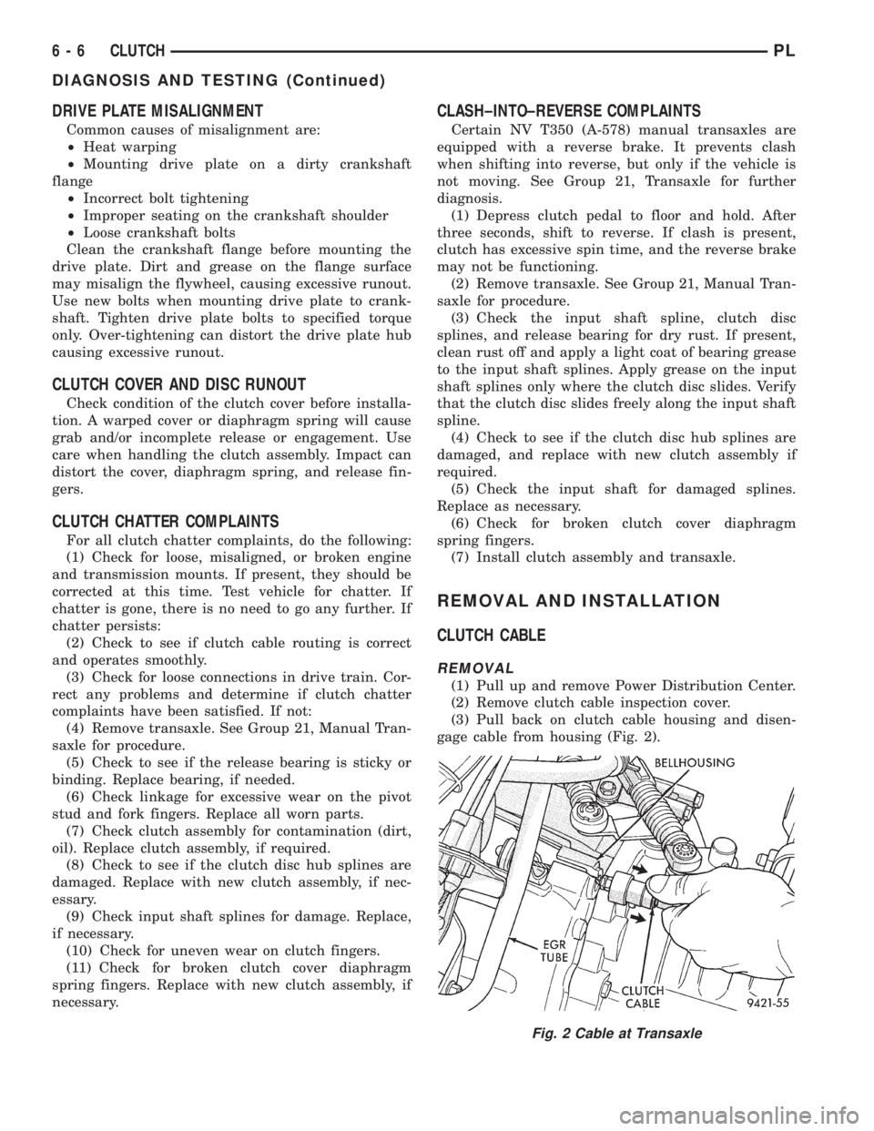
gage cable from housing (Fig. 2).
Fig. 2 Cable at Transaxle
6 - 6 CLUTCHPL
DIAGNOSIS AND TESTING (Continued)
Page 179 of 1200
REMOVAL
(1) Remove transaxle. See Group 21, Manual Tran-
saxle, for procedure.
(2) Mark clutch cover and flywheel, to maintain
their same relative positions when installing clutch
assembly.
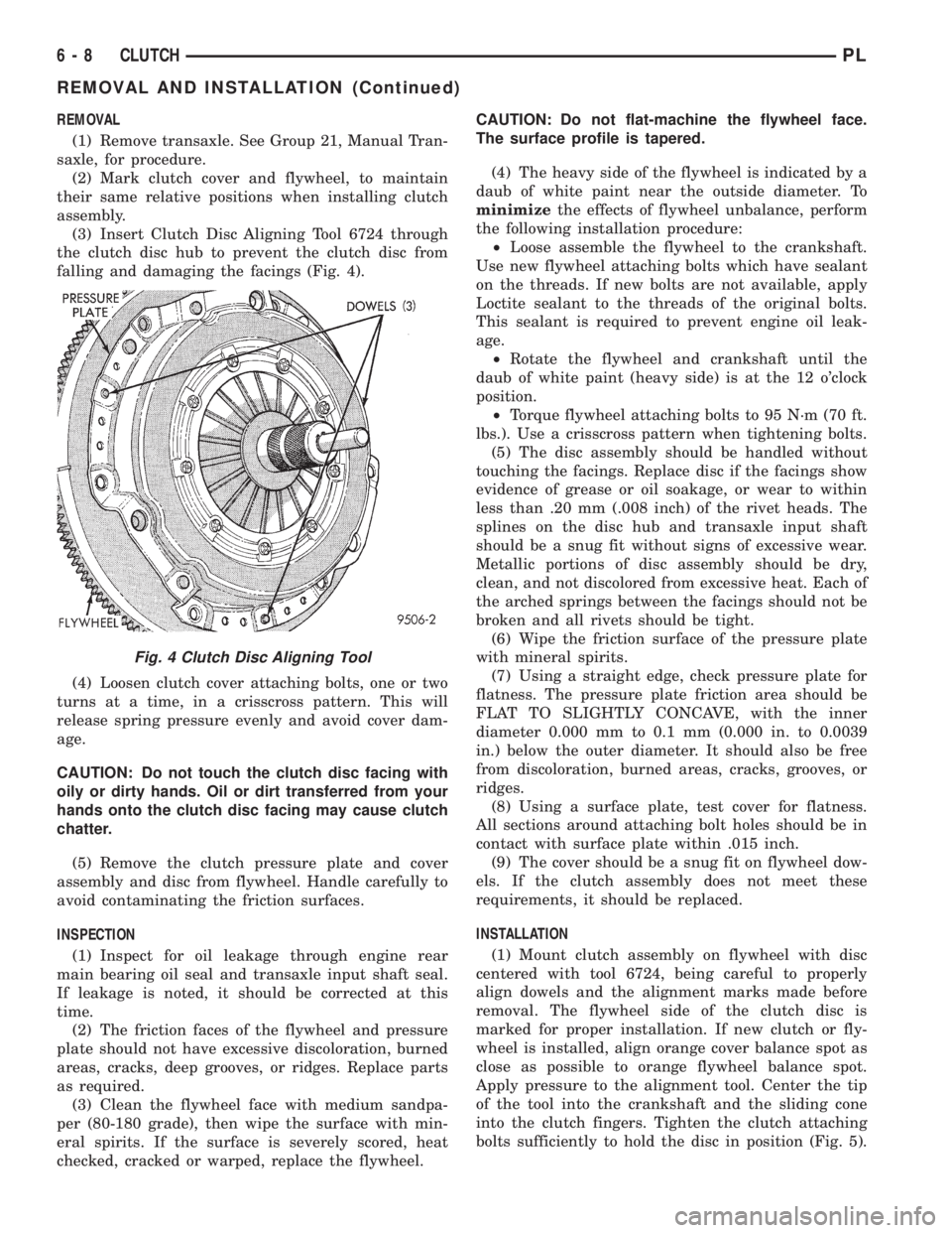
(3) Insert Clutch Disc Aligning Tool 6724 through
the clutch disc hub to prevent the clutch disc from
falling and damaging the facings (Fig. 4).
(4) Loosen clutch cover attaching bolts, one or two
turns at a time, in a crisscross pattern. This will
release spring pressure evenly and avoid cover dam-
age.
CAUTION: Do not touch the clutch disc facing with
oily or dirty hands. Oil or dirt transferred from your
hands onto the clutch disc facing may cause clutch
chatter.
(5) Remove the clutch pressure plate and cover
assembly and disc from flywheel. Handle carefully to
avoid contaminating the friction surfaces.
INSPECTION
(1) Inspect for oil leakage through engine rear
main bearing oil seal and transaxle input shaft seal.
If leakage is noted, it should be corrected at this
time.
(2) The friction faces of the flywheel and pressure
plate should not have excessive discoloration, burned
areas, cracks, deep grooves, or ridges. Replace parts
as required.
(3) Clean the flywheel face with medium sandpa-
per (80-180 grade), then wipe the surface with min-
eral spirits. If the surface is severely scored, heat
checked, cracked or warped, replace the flywheel.CAUTION: Do not flat-machine the flywheel face.
The surface profile is tapered.
(4) The heavy side of the flywheel is indicated by a
daub of white paint near the outside diameter. To
minimizethe effects of flywheel unbalance, perform
the following installation procedure:
²Loose assemble the flywheel to the crankshaft.
Use new flywheel attaching bolts which have sealant
on the threads. If new bolts are not available, apply
Loctite sealant to the threads of the original bolts.
This sealant is required to prevent engine oil leak-
age.
²Rotate the flywheel and crankshaft until the
daub of white paint (heavy side) is at the 12 o'clock
position.
²Torque flywheel attaching bolts to 95 N´m (70 ft.
lbs.). Use a crisscross pattern when tightening bolts.
(5) The disc assembly should be handled without
touching the facings. Replace disc if the facings show
evidence of grease or oil soakage, or wear to within
less than .20 mm (.008 inch) of the rivet heads. The
splines on the disc hub and transaxle input shaft
should be a snug fit without signs of excessive wear.
Metallic portions of disc assembly should be dry,
clean, and not discolored from excessive heat. Each of
the arched springs between the facings should not be
broken and all rivets should be tight.
(6) Wipe the friction surface of the pressure plate
with mineral spirits.
(7) Using a straight edge, check pressure plate for
flatness. The pressure plate friction area should be
FLAT TO SLIGHTLY CONCAVE, with the inner
diameter 0.000 mm to 0.1 mm (0.000 in. to 0.0039
in.) below the outer diameter. It should also be free
from discoloration, burned areas, cracks, grooves, or
ridges.
(8) Using a surface plate, test cover for flatness.
All sections around attaching bolt holes should be in
contact with surface plate within .015 inch.
(9) The cover should be a snug fit on flywheel dow-
els. If the clutch assembly does not meet these
requirements, it should be replaced.
INSTALLATION
(1) Mount clutch assembly on flywheel with disc
centered with tool 6724, being careful to properly
align dowels and the alignment marks made before
removal. The flywheel side of the clutch disc is
marked for proper installation. If new clutch or fly-
wheel is installed, align orange cover balance spot as
close as possible to orange flywheel balance spot.
Apply pressure to the alignment tool. Center the tip
of the tool into the crankshaft and the sliding cone
into the clutch fingers. Tighten the clutch attaching
bolts sufficiently to hold the disc in position (Fig. 5).
Fig. 4 Clutch Disc Aligning Tool
6 - 8 CLUTCHPL
REMOVAL AND INSTALLATION (Continued)
Page 180 of 1200
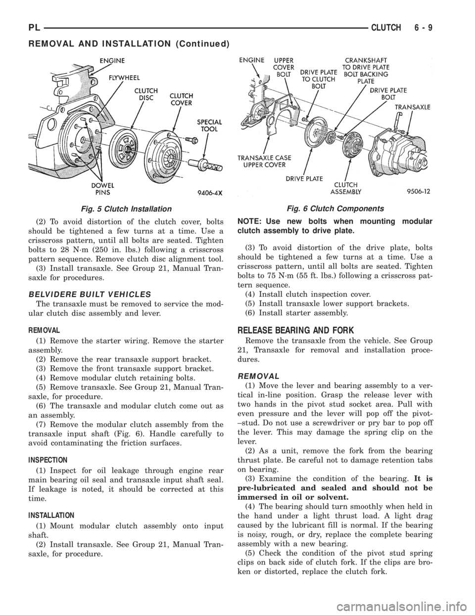
(2) To avoid distortion of the clutch cover, bolts
should be tightened a few turns at a time. Use a
crisscross pattern, until all bolts are seated. Tighten
bolts to 28 N´m (250 in. lbs.) following a crisscross
pattern sequence. Remove clutch disc alignment tool.
(3) Install transaxle. See Group 21, Manual Tran-
saxle for procedures.
BELVIDERE BUILT VEHICLES
The transaxle must be removed to service the mod-
ular clutch disc assembly and lever.
REMOVAL
(1) Remove the starter wiring. Remove the starter
assembly.
(2) Remove the rear transaxle support bracket.
(3) Remove the front transaxle support bracket.
(4) Remove modular clutch retaining bolts.
(5) Remove transaxle. See Group 21, Manual Tran-
saxle, for procedure.
(6) The transaxle and modular clutch come out as
an assembly.
(7) Remove the modular clutch assembly from the
transaxle input shaft (Fig. 6). Handle carefully to
avoid contaminating the friction surfaces.
INSPECTION
(1) Inspect for oil leakage through engine rear
main bearing oil seal and transaxle input shaft seal.
If leakage is noted, it should be corrected at this
time.
INSTALLATION
(1) Mount modular clutch assembly onto input
shaft.
(2) Install transaxle. See Group 21, Manual Tran-
saxle, for procedure.NOTE: Use new bolts when mounting modular
clutch assembly to drive plate.
(3) To avoid distortion of the drive plate, bolts
should be tightened a few turns at a time. Use a
crisscross pattern, until all bolts are seated. Tighten
bolts to 75 N´m (55 ft. lbs.) following a crisscross pat-
tern sequence.
(4) Install clutch inspection cover.
(5) Install transaxle lower support brackets.
(6) Install starter assembly.
RELEASE BEARING AND FORK
Remove the transaxle from the vehicle. See Group
21, Transaxle for removal and installation proce-
dures.
REMOVAL
(1) Move the lever and bearing assembly to a ver-
tical in-line position. Grasp the release lever with
two hands in the pivot stud socket area. Pull with
even pressure and the lever will pop off the pivot-
±stud. Do not use a screwdriver or pry bar to pop off
the lever. This may damage the spring clip on the
lever.
(2) As a unit, remove the fork from the bearing
thrust plate. Be careful not to damage retention tabs
on bearing.
(3) Examine the condition of the bearing.It is
pre-lubricated and sealed and should not be
immersed in oil or solvent.
(4) The bearing should turn smoothly when held in
the hand under a light thrust load. A light drag
caused by the lubricant fill is normal. If the bearing
is noisy, rough, or dry, replace the complete bearing
assembly with a new bearing.
(5) Check the condition of the pivot stud spring
clips on back side of clutch fork. If the clips are bro-
ken or distorted, replace the clutch fork.
Fig. 6 Clutch ComponentsFig. 5 Clutch Installation
PLCLUTCH 6 - 9
REMOVAL AND INSTALLATION (Continued)
Page 186 of 1200
SERVICE DIAGNOSISÐCLUTCH GRAB/CHATTER
CONDITION POSSIBLE CAUSES CORRECTION
CLUTCH DISC FACING
COVERED WITH OIL OR
GREASEOil leak at engine rear main or
transaxle input shaft sealCorrect leak and replace w/modular
clutch assembly
Too much grease applied to splines
of disc and input shaftApply lighter coating of grease to
splines
NO FAULT FOUND WITH
CLUTCH
COMPONENTSProblem actually related to
suspension or driveline componentFurther diagnosis required. Check
engine/transmission mounts,
suspension attaching parts and other
driveline components as needed.
Engine related problems Check EFI and ignition systems
PARTIAL ENGAGEMENT OF
CLUTCH DISCClutch cover, spring, or release
fingers bent, distorted (rough
handling, improper assembly)Replace w/modular clutch assembly
Clutch disc damaged or distorted Replace w/modular clutch assembly
Clutch misalignment Check alignment and runout of
flywheel, disc, or cover. Check clutch
housing to engine dowels and dowel
holes for damage. Correct as
necessary.
PLCLUTCH 6 - 3
DIAGNOSIS AND TESTING (Continued)
Page 206 of 1200
ENGINE THERMOSTAT TESTING
The thermostat is operated by a wax filled con-
tainer (pellet) which is sealed. When heated coolant
reaches a predetermined temperature the wax pellet
expands enough to overcome the closing spring and
water pump pressure, which forces the valve to open.
Coolant leakage into the pellet will cause a thermo-
stat to fail open. Do not attempt to free up a thermo-
stat with a screwdriver.The thermostat that opens too soon type failure
mode is included in the on-board diagnosis. The
check engine light will not be lit by an open too soon
condition. If it has failed open, a diagnostic trouble
code (DTC) will be set. Do not change a thermostat
for lack of heater performance or temperature gauge
position, unless a DTC is present. See Diagnosis for
other probable causes. Thermostat failing shut is the
normal long term mode of failure, and normally, only
on high mileage vehicles. The temperature gauge will
indicate this. Refer to Diagnosis in this section.
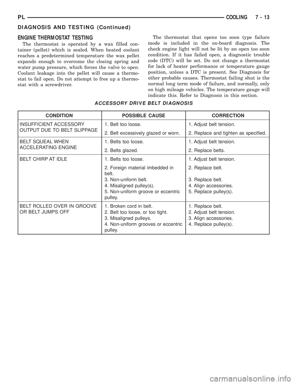
ACCESSORY DRIVE BELT DIAGNOSIS
CONDITION POSSIBLE CAUSE CORRECTION
INSUFFICIENT ACCESSORY
OUTPUT DUE TO BELT SLIPPAGE1. Belt too loose. 1. Adjust belt tension.
2. Belt excessively glazed or worn. 2. Replace and tighten as specified.
BELT SQUEAL WHEN
ACCELERATING ENGINE1. Belts too loose. 1. Adjust belt tension.
2. Belts glazed. 2. Replace belts.
BELT CHIRP AT IDLE 1. Belts too loose. 1. Adjust belt tension.
2. Foreign material imbedded in
belt.2. Replace belt.
3. Non-uniform belt. 3. Replace belt.
4. Misaligned pulley(s). 4. Align accessories.
5. Non-uniform groove or eccentric
pulley.5. Replace pulley(s).
BELT ROLLED OVER IN GROOVE
OR BELT JUMPS OFF1. Broken cord in belt. 1. Replace belt.
2. Belt too loose, or too tight. 2. Adjust belt tension.
3. Misaligned pulleys. 3. Align accessories.
4. Non-uniform grooves or eccentric
pulley.4. Replace pulley(s).
PLCOOLING 7 - 13
DIAGNOSIS AND TESTING (Continued)
Page 209 of 1200
escapes to the atmosphere in the CRS tank and is
replaced with solid coolant on cool down.
TEMPERATURE GAUGE INDICATION
At idle the temperature gauge could rise slowly to
about 1/2 gauge travel. The fan will come on and the
gauge could drop to about 1/3 gauge travel, this is
normal.
SERVICE PROCEDURES
COOLANT LEVEL CHECKÐROUTINE
NOTE: Do not remove radiator cap for routine cool-
ant level inspections.
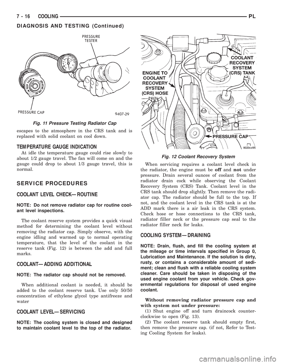
The coolant reserve system provides a quick visual
method for determining the coolant level without
removing the radiator cap. Simply observe, with the
engine idling and warmed up to normal operating
temperature, that the level of the coolant in the
reserve tank (Fig. 12) is between the add and full
marks.
COOLANTÐADDING ADDITIONAL
NOTE: The radiator cap should not be removed.
When additional coolant is needed, it should be
added to the coolant reserve tank. Use only 50/50
concentration of ethylene glycol type antifreeze and
water
COOLANT LEVELÐSERVICING
NOTE: The cooling system is closed and designed
to maintain coolant level to the top of the radiator.When servicing requires a coolant level check in
the radiator, the engine must beoffandnotunder
pressure. Drain several ounces of coolant from the
radiator drain cock while observing the Coolant
Recovery System (CRS) Tank. Coolant level in the
CRS tank should drop slightly. Then remove the radi-
ator cap. The radiator should be full to the top. If
not, and the coolant level in the CRS tank is at the
ADD mark there is a air leak in the CRS system.
Check hose or hose connections to the CRS tank,
radiator filler neck or the pressure cap seal to the
radiator filler neck for leaks.
COOLING SYSTEMÐDRAINING
NOTE: Drain, flush, and fill the cooling system at
the mileage or time intervals specified in Group 0,
Lubrication and Maintenance. If the solution is dirty,
rusty, or contains a considerable amount of sedi-
ment; clean and flush with a reliable cooling system
cleaner. Care should be taken in disposing of the
used engine coolant from your vehicle. Check gov-
ernmental regulations for disposal of used engine
coolant.
Without removing radiator pressure cap and
with system not under pressure:
(1) Shut engine off and turn draincock counter-
clockwise to open (Fig. 13).
(2) The coolant reserve tank should empty first,
then remove the pressure cap. (if not, Refer to Test-
ing Cooling System for leaks).
Fig. 11 Pressure Testing Radiator Cap
Fig. 12 Coolant Recovery System
7 - 16 COOLINGPL
DIAGNOSIS AND TESTING (Continued)