1999 DODGE NEON check engine light
[x] Cancel search: check engine lightPage 912 of 1200
should be in the range of 345-552 kPa (50-80 psi).
The flow meter should read between 1.3 and 1.4
GPM
CAUTION: The following test procedure involves
testing power steering pump maximum pressure
output and flow control valve operation. Do not
leave valve closed for more than 5 seconds as the
pump could be damaged.
(8) Close valve fully three times and record high-
est pressure indicated each time.All three read-
ings must be above specifications and within
345 kPa (50 psi) of each other.
NOTE: Power steering pump maximum relief pres-
sure is 8240 to 8920 kPa (1195 to 1293 psi.).
²If power steering pump pressures above specifi-
cations but not within 345 kPa (50 psi) of each other,
then replace power steering pump.
²If pressures within 345 kPa (50 psi) of each
other but below specifications, then replace power
steering pump.
CAUTION: Do not force the pump to operate
against the stops for more than 5 seconds at a time
because, pump damage will result.
(9) Open test valve. Turn steering wheel to the
extreme left and right positions until against the
stops, recording the highest indicated pressure at
each position. Compare pressure gauge readings to
power steering pump specifications. If highest output
pressures are not the same against either stop, the
steering gear is leaking internally and must be
replaced.
SERVICE PROCEDURES
POWER STEERING SYSTEM FLUID LEVEL CHECK
WARNING: FLUID LEVEL SHOULD BE CHECKED
WITH ENGINE OFF TO PREVENT INJURY FROM
MOVING PARTS. DO NOT USE AUTOMATIC TRANS-
MISSION FLUID IN THE POWER STEERING SYS-
TEM. DO NOT OVERFILL THE POWER STEERING
SYSTEM.
Wipe reservoir filler cap free of dirt. Then check
fluid level. The dipstick should indicate COLD when
fluid is at normal ambient temperature, approxi-
mately 21ÉC to 27ÉC (70ÉF to 80ÉF). In all pumps add
fluid as necessary, use onlyMopar Power Steering
Fluid, or equivalent. DO NOT USE ANY TYPE
OF AUTOMATIC TRANSMISSION FLUID.
POWER STEERING PUMP INITIAL OPERATION
CAUTION: The fluid level should be checked with
engine off to prevent injury from moving compo-
nents. Use only MoparTPower Steering Fluid. Do
not use automatic transmission fluid. Do not over-
fill.
Wipe filler cap clean, then check the fluid level.
The dipstick should indicateFULL COLDwhen the
fluid is at normal temperature of approximately 21ÉC
to 27ÉC (70ÉF to 80ÉF).
(1) Fill the pump fluid reservoir to the proper level
and let the fluid settle for at least two (2) minutes.
(2) Start the engine and let run for a few seconds.
Then turn the engine off.
(3) Add fluid if necessary. Repeat the above proce-
dure until the fluid level remains constant after run-
ning the engine.
(4) Raise the front wheels off the ground.
(5) Start the engine. Slowly turn the steering
wheel right and left, lightly contacting the wheel
stops.
(6) Add power steering fluid if necessary.
(7) Lower the vehicle and turn the steering wheel
slowly from lock to lock.
(8) Stop the engine. Check the fluid level and refill
as required.
(9) If the fluid is extremely foamy, allow the vehi-
cle to stand a few minutes and repeat the above pro-
cedure.
POWER STEERING PUMP FLOW CONTROL VALVE
SEAL
The power steering pump does not require removal
from the engine for removal and replacement of the
flow control valve fitting O-Ring.
REMOVE
(1) Remove the power steering fluid pressure hose
from the power steering pump pressure fitting (Fig.
4).
(2) Remove the flow control valve fitting from the
power steering pump housing (Fig. 5).Prevent flow
control valve and spring from sliding out of
housing bore.
(3) Remove and discard O-ring seal from fitting.
INSTALL
(1) If necessary, clean and install flow control
valve and spring in pump housing bore.
(2) Install new O-ring seal on fitting.
(3) Install fitting in pump housing and tighten to
75 N´m (55 ft. lbs.)
(4) Install power steering fluid pressure hose on
flow control valve fitting.
PLSTEERING 19 - 11
DIAGNOSIS AND TESTING (Continued)
Page 916 of 1200
(8) Correctly route power steering pressure hose
avoiding tight bends or kinking of the hose. Install
power steering pressure hose to generator shield
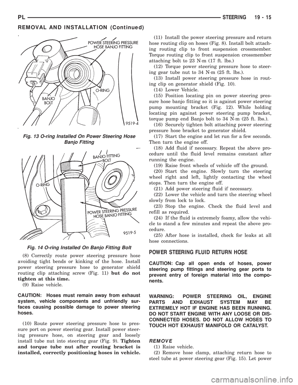
routing clip attaching screw (Fig. 11)but do not
tighten at this time.
(9) Raise vehicle.
CAUTION: Hoses must remain away from exhaust
system, vehicle components and unfriendly sur-
faces causing possible damage to power steering
hoses.
(10) Route power steering pressure hose to pres-
sure port on power steering gear. Install power steer-
ing pressure hose, on steering gear and loosely
install tube nut into steering gear (Fig. 9).Tighten
and torque tube nut after routing bracket is
installed, correctly positioning hoses in vehicle.(11) Install the power steering pressure and return
hose routing clip on hoses (Fig. 8). Install bolt attach-
ing routing clip to front suspension crossmember.
Torque routing clip to front suspension crossmember
attaching bolt to 23 N´m (17 ft. lbs.)
(12) Torque power steering pressure hose to steer-
ing gear tube nut to 34 N´m (25 ft. lbs.).
(13) Install power steering pressure hose in rout-
ing clip on generator shield (Fig. 10).
(14) Lower Vehicle.
(15) Position locating pin on power steering pres-
sure hose banjo fitting so it is against power steering
pump mounting bracket (Fig. 12). While holding
locating pin against power steering pump bracket,
torque pump end Banjo bolt to 34 N´m (25 ft. lbs.).
(16) Securely tighten bolt attaching power steering
pressure hose bracket to generator shield.
(17) Start the engine and let run for a few seconds.
Then turn the engine off.
(18) Add fluid if necessary. Repeat the above pro-
cedure until the fluid level remains constant after
running the engine.
(19) Raise front wheels of vehicle off the ground.
(20) Start the engine. Slowly turn the steering
wheel right and left, lightly contacting the wheel
stops. Then turn the engine off.
(21) Add power steering fluid if necessary.
(22) Lower the vehicle and turn the steering wheel
slowly from lock to lock.
(23) Stop the engine. Check the fluid level and
refill as required.
(24) If the fluid is extremely foamy, allow the vehi-
cle to stand a few minutes and repeat the above pro-
cedure.
(25) After hose is installed, check for leaks at all
hose connections.POWER STEERING FLUID RETURN HOSE
CAUTION: Cap all open ends of hoses, power
steering pump fittings and steering gear ports to
prevent entry of foreign material into the compo-
nents.
WARNING: POWER STEERING OIL, ENGINE
PARTS AND EXHAUST SYSTEM MAY BE
EXTREMELY HOT IF ENGINE HAS BEEN RUNNING.
DO NOT START ENGINE WITH ANY LOOSE OR DIS-
CONNECTED HOSES. DO NOT ALLOW HOSES TO
TOUCH HOT EXHAUST MANIFOLD OR CATALYST.
REMOVE
(1) Raise vehicle.
(2) Remove hose clamp, attaching return hose to
steel tube at power steering gear (Fig. 15). Let power
Fig. 13 O-ring Installed On Power Steering Hose
Banjo Fitting
Fig. 14 O-ring Installed On Banjo Fitting Bolt
PLSTEERING 19 - 15
REMOVAL AND INSTALLATION (Continued)
Page 918 of 1200
installed on return hose past upset bead on
power steering fluid reservoir.
(3) Raise vehicle.
(4) Clip power steering return hose and pressure
hose together (Fig. 17).
(5) Install power steering return hose on steel tube
at power steering gear (Fig. 15). Install hose clamp
on power steering return hose at power steering gear
(Fig. 15).Be sure hose clamp is installed on
return hose past upset bead on steel tube at
power gear.
(6) Install power steering return hose on routing
clip at generator shield (Fig. 16).
(7) Lower vehicle.
(8) Start the engine and let run for a few seconds.
Then turn the engine off.
(9) Add fluid if necessary. Repeat the above proce-
dure until the fluid level remains constant after run-
ning the engine.
(10) Raise front wheels of vehicle off the ground.
(11) Start the engine. Slowly turn the steering
wheel right and left, lightly contacting the wheel
stops. Then turn the engine off.
(12) Add power steering fluid if necessary.
(13) Lower the vehicle and turn the steering wheel
slowly from lock to lock.
(14) Stop the engine. Check the fluid level and
refill as required.
(15) If the fluid is extremely foamy, allow the vehi-
cle to stand a few minutes and repeat the above pro-
cedure.
(16) After hose is installed, check for leaks at all
hose connections.
POWER STEERING FLUID SUPPLY HOSE
RESERVOIR TO POWER STEERING PUMP
WARNING: POWER STEERING OIL, ENGINE
PARTS AND EXHAUST SYSTEM MAY BE
EXTREMELY HOT IF ENGINE HAS BEEN RUNNING.
DO NOT START ENGINE WITH ANY LOOSE OR DIS-
CONNECTED HOSES. DO NOT ALLOW HOSES TO
TOUCH HOT EXHAUST MANIFOLD OR CATALYST.
REMOVE
CAUTION: Care must be used when removing the
power steering fluid supply hose from power steer-
ing fluid reservoir. If excessive force is used when
trying to remove hose from nipple on power steer-
ing fluid reservoir, nipple can break off of the res-
ervoir.
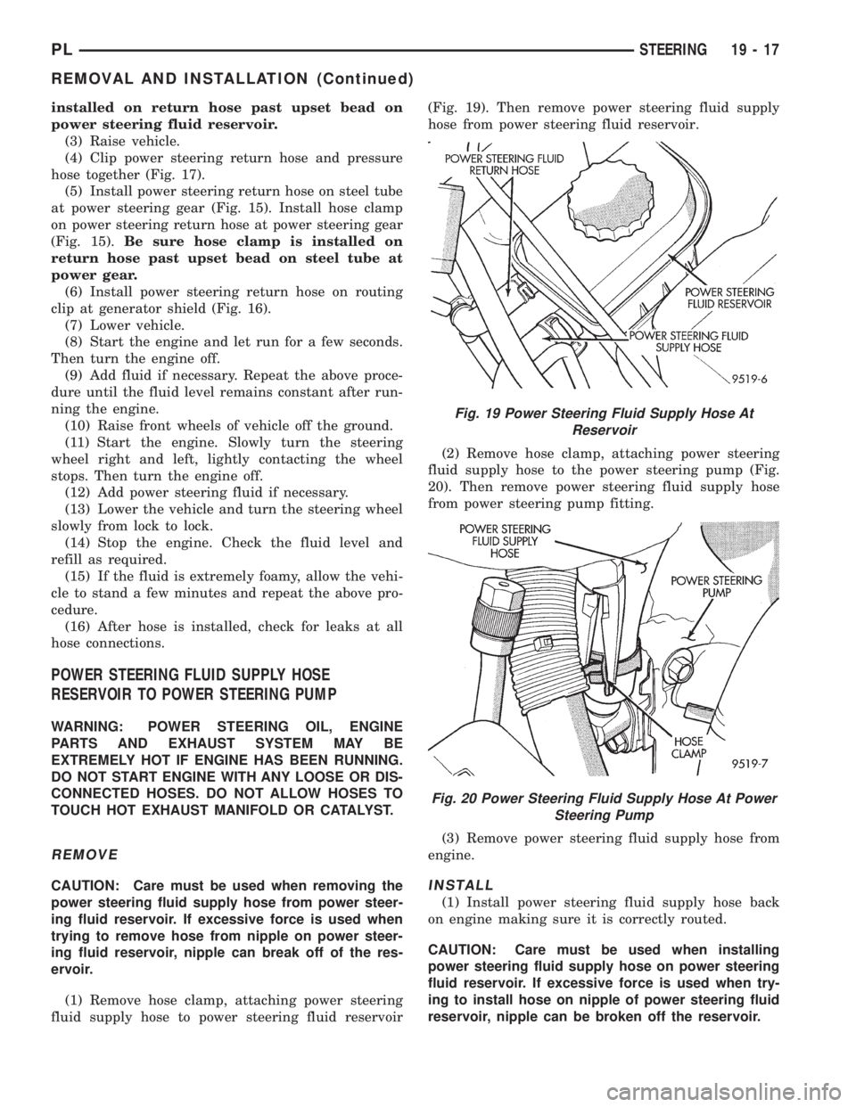
(1) Remove hose clamp, attaching power steering
fluid supply hose to power steering fluid reservoir(Fig. 19). Then remove power steering fluid supply
hose from power steering fluid reservoir.
(2) Remove hose clamp, attaching power steering
fluid supply hose to the power steering pump (Fig.
20). Then remove power steering fluid supply hose
from power steering pump fitting.
(3) Remove power steering fluid supply hose from
engine.INSTALL
(1) Install power steering fluid supply hose back
on engine making sure it is correctly routed.
CAUTION: Care must be used when installing
power steering fluid supply hose on power steering
fluid reservoir. If excessive force is used when try-
ing to install hose on nipple of power steering fluid
reservoir, nipple can be broken off the reservoir.
Fig. 19 Power Steering Fluid Supply Hose At
Reservoir
Fig. 20 Power Steering Fluid Supply Hose At Power
Steering Pump
PLSTEERING 19 - 17
REMOVAL AND INSTALLATION (Continued)
Page 919 of 1200
(2) Install power steering fluid supply hose on
power steering fluid reservoir fitting. Install hose
clamp on power steering fluid supply hose at power
steering fluid reservoir (Fig. 19).Be sure hose
clamp is installed on return hose past upset
bead on power steering fluid reservoir.
(3) Install power steering fluid supply hose on
power steering pump fitting. Install hose clamp on
power steering fluid supply hose at power steering
pump fitting (Fig. 20).Be sure hose clamp is
installed on power steering fluid supply hose
past upset bead on power steering pump fit-
ting.
(4) Start the engine and let run for a few seconds.
Then turn the engine off.
(5) Add fluid if necessary. Repeat the above proce-
dure until the fluid level remains constant after run-
ning the engine.
(6) Raise front wheels of vehicle off the ground.
(7) Start the engine. Slowly turn the steering
wheel right and left, lightly contacting the wheel
stops. Then turn the engine off.
(8) Add power steering fluid if necessary.
(9) Lower the vehicle and turn the steering wheel
slowly from lock to lock.
(10) Stop the engine. Check the fluid level and
refill as required.
(11) If the fluid is extremely foamy, allow the vehi-
cle to stand a few minutes and repeat the above pro-
cedure.
(12) After hose is installed, check for leaks at all
hose connections.
POWER STEERING PUMP (ALL ENGINES)
WARNING: POWER STEERING OIL, ENGINE COM-
PONENTS AND EXHAUST SYSTEM MAY BE
EXTREMELY HOT IF ENGINE HAS BEEN RUNNING.
DO NOT START ENGINE WITH ANY LOOSE OR DIS-
CONNECTED HOSES, OR ALLOW HOSES TO
TOUCH HOT EXHAUST MANIFOLD OR CATALYST.
The power steering pump removal procedure and
pump and bracket fastener locations are the same for
both engine applications used for this vehicle. The
front power steering pump bracket must be removed
as an assembly with the power steering pump and
removed from the pump after removing the pulley
from the power steering pump.
REMOVE
(1) Remove battery cable from (-) negative post on
battery.
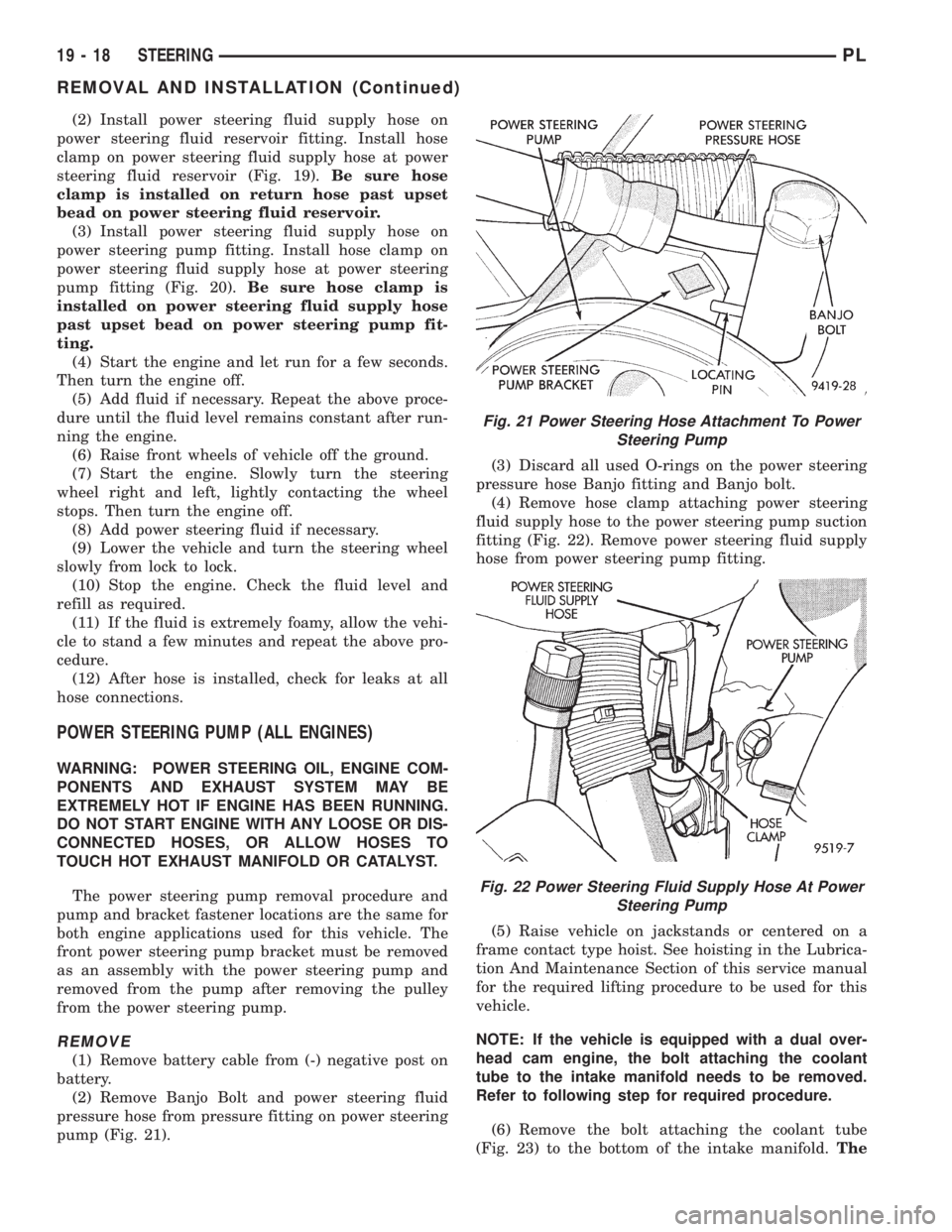
(2) Remove Banjo Bolt and power steering fluid
pressure hose from pressure fitting on power steering
pump (Fig. 21).(3) Discard all used O-rings on the power steering
pressure hose Banjo fitting and Banjo bolt.
(4) Remove hose clamp attaching power steering
fluid supply hose to the power steering pump suction
fitting (Fig. 22). Remove power steering fluid supply
hose from power steering pump fitting.
(5) Raise vehicle on jackstands or centered on a
frame contact type hoist. See hoisting in the Lubrica-
tion And Maintenance Section of this service manual
for the required lifting procedure to be used for this
vehicle.
NOTE: If the vehicle is equipped with a dual over-
head cam engine, the bolt attaching the coolant
tube to the intake manifold needs to be removed.
Refer to following step for required procedure.
(6) Remove the bolt attaching the coolant tube
(Fig. 23) to the bottom of the intake manifold.The
Fig. 21 Power Steering Hose Attachment To Power
Steering Pump
Fig. 22 Power Steering Fluid Supply Hose At Power
Steering Pump
19 - 18 STEERINGPL
REMOVAL AND INSTALLATION (Continued)
Page 921 of 1200
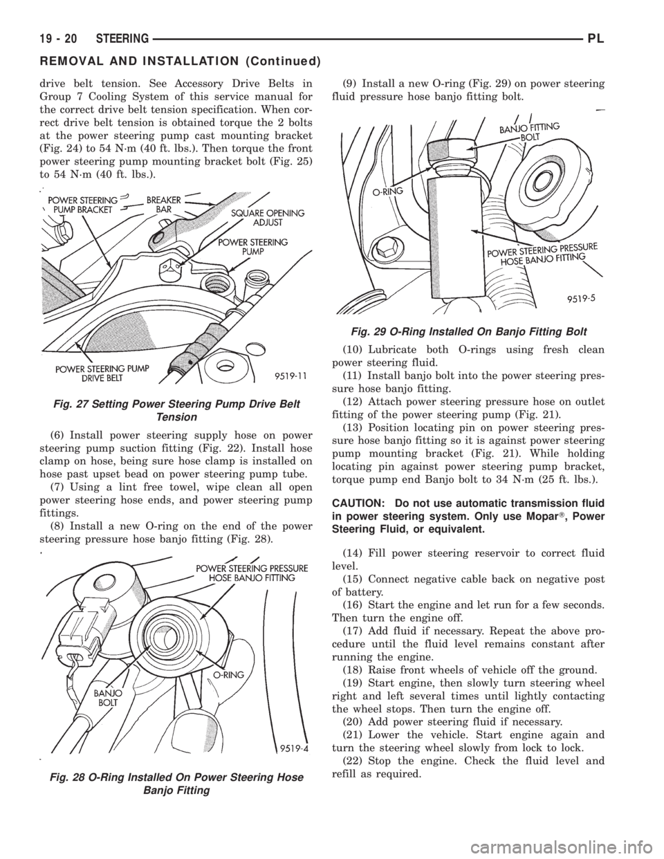
drive belt tension. See Accessory Drive Belts in
Group 7 Cooling System of this service manual for
the correct drive belt tension specification. When cor-
rect drive belt tension is obtained torque the 2 bolts
at the power steering pump cast mounting bracket
(Fig. 24) to 54 N´m (40 ft. lbs.). Then torque the front
power steering pump mounting bracket bolt (Fig. 25)
to 54 N´m (40 ft. lbs.).
(6) Install power steering supply hose on power
steering pump suction fitting (Fig. 22). Install hose
clamp on hose, being sure hose clamp is installed on
hose past upset bead on power steering pump tube.
(7) Using a lint free towel, wipe clean all open
power steering hose ends, and power steering pump
fittings.
(8) Install a new O-ring on the end of the power
steering pressure hose banjo fitting (Fig. 28).(9) Install a new O-ring (Fig. 29) on power steering
fluid pressure hose banjo fitting bolt.
(10) Lubricate both O-rings using fresh clean
power steering fluid.
(11) Install banjo bolt into the power steering pres-
sure hose banjo fitting.
(12) Attach power steering pressure hose on outlet
fitting of the power steering pump (Fig. 21).
(13) Position locating pin on power steering pres-
sure hose banjo fitting so it is against power steering
pump mounting bracket (Fig. 21). While holding
locating pin against power steering pump bracket,
torque pump end Banjo bolt to 34 N´m (25 ft. lbs.).
CAUTION: Do not use automatic transmission fluid
in power steering system. Only use MoparT, Power
Steering Fluid, or equivalent.
(14) Fill power steering reservoir to correct fluid
level.
(15) Connect negative cable back on negative post
of battery.
(16) Start the engine and let run for a few seconds.
Then turn the engine off.
(17) Add fluid if necessary. Repeat the above pro-
cedure until the fluid level remains constant after
running the engine.
(18) Raise front wheels of vehicle off the ground.
(19) Start engine, then slowly turn steering wheel
right and left several times until lightly contacting
the wheel stops. Then turn the engine off.
(20) Add power steering fluid if necessary.
(21) Lower the vehicle. Start engine again and
turn the steering wheel slowly from lock to lock.
(22) Stop the engine. Check the fluid level and
refill as required.
Fig. 27 Setting Power Steering Pump Drive Belt
Tension
Fig. 28 O-Ring Installed On Power Steering Hose
Banjo Fitting
Fig. 29 O-Ring Installed On Banjo Fitting Bolt
19 - 20 STEERINGPL
REMOVAL AND INSTALLATION (Continued)
Page 923 of 1200
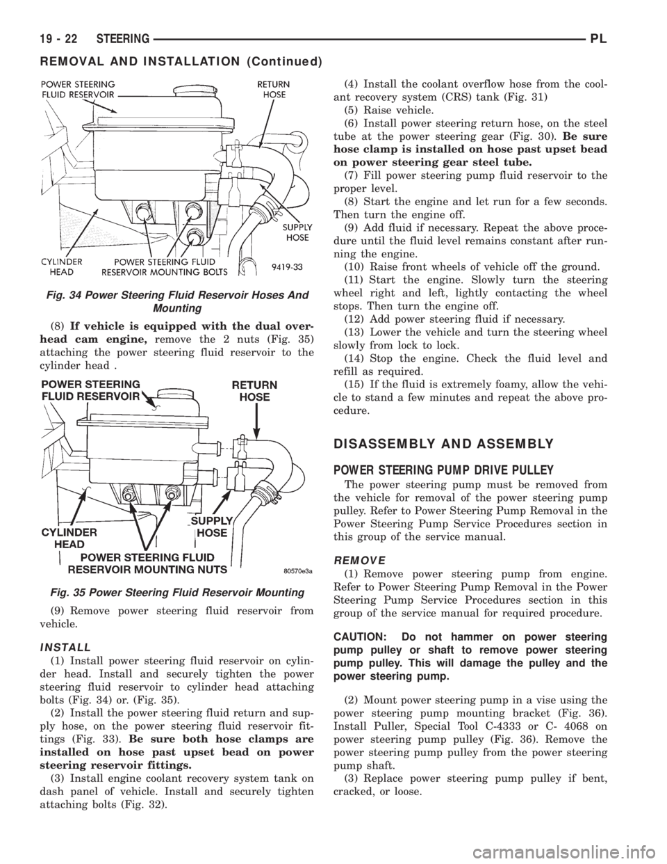
(8)If vehicle is equipped with the dual over-
head cam engine,remove the 2 nuts (Fig. 35)
attaching the power steering fluid reservoir to the
cylinder head .
(9) Remove power steering fluid reservoir from
vehicle.
INSTALL
(1) Install power steering fluid reservoir on cylin-
der head. Install and securely tighten the power
steering fluid reservoir to cylinder head attaching
bolts (Fig. 34) or. (Fig. 35).
(2) Install the power steering fluid return and sup-
ply hose, on the power steering fluid reservoir fit-
tings (Fig. 33).Be sure both hose clamps are
installed on hose past upset bead on power
steering reservoir fittings.
(3) Install engine coolant recovery system tank on
dash panel of vehicle. Install and securely tighten
attaching bolts (Fig. 32).(4) Install the coolant overflow hose from the cool-
ant recovery system (CRS) tank (Fig. 31)
(5) Raise vehicle.
(6) Install power steering return hose, on the steel
tube at the power steering gear (Fig. 30).Be sure
hose clamp is installed on hose past upset bead
on power steering gear steel tube.
(7) Fill power steering pump fluid reservoir to the
proper level.
(8) Start the engine and let run for a few seconds.
Then turn the engine off.
(9) Add fluid if necessary. Repeat the above proce-
dure until the fluid level remains constant after run-
ning the engine.
(10) Raise front wheels of vehicle off the ground.
(11) Start the engine. Slowly turn the steering
wheel right and left, lightly contacting the wheel
stops. Then turn the engine off.
(12) Add power steering fluid if necessary.
(13) Lower the vehicle and turn the steering wheel
slowly from lock to lock.
(14) Stop the engine. Check the fluid level and
refill as required.
(15) If the fluid is extremely foamy, allow the vehi-
cle to stand a few minutes and repeat the above pro-
cedure.
DISASSEMBLY AND ASSEMBLY
POWER STEERING PUMP DRIVE PULLEY
The power steering pump must be removed from
the vehicle for removal of the power steering pump
pulley. Refer to Power Steering Pump Removal in the
Power Steering Pump Service Procedures section in
this group of the service manual.
REMOVE
(1) Remove power steering pump from engine.
Refer to Power Steering Pump Removal in the Power
Steering Pump Service Procedures section in this
group of the service manual for required procedure.
CAUTION: Do not hammer on power steering
pump pulley or shaft to remove power steering
pump pulley. This will damage the pulley and the
power steering pump.
(2) Mount power steering pump in a vise using the
power steering pump mounting bracket (Fig. 36).
Install Puller, Special Tool C-4333 or C- 4068 on
power steering pump pulley (Fig. 36). Remove the
power steering pump pulley from the power steering
pump shaft.
(3) Replace power steering pump pulley if bent,
cracked, or loose.
Fig. 34 Power Steering Fluid Reservoir Hoses And
Mounting
Fig. 35 Power Steering Fluid Reservoir Mounting
19 - 22 STEERINGPL
REMOVAL AND INSTALLATION (Continued)
Page 1001 of 1200
(8) Recheck fluid level after transaxle is at normal
operating temperature. The level should be in the
HOT region.
ALUMINUM THREAD REPAIR
Damaged or worn threads in the aluminum tran-
saxle case and valve body can be repaired by the use
of Heli-Coils. This repair consists of drilling out the
worn-out or damaged threads. Then tap the hole with
a Heli-Coil tap, and install a Heli-Coil insert into the
hole. This brings the hole back to its original thread
size.
Heli-Coil tools and inserts are readily available
from most automotive parts suppliers.
FLUSHING COOLERS AND TUBES
When a transaxle failure has contaminated the
fluid, the oil cooler(s) must be flushed. The cooler
bypass valve in the transaxle must be replaced also.
The torque converter must also be replaced with an
exchange unit. This will ensure that metal particles
or sludged oil are not later transferred back into the
reconditioned (or replaced) transaxle.
The recommended procedure for flushing the cool-
ers and tubes is to use Tool 6906A Cooler Flusher.
WARNING: WEAR PROTECTIVE EYEWEAR THAT
MEETS THE REQUIREMENTS OF OSHA AND ANSI
Z87.1±1968. WEAR STANDARD INDUSTRIAL RUB-
BER GLOVES.
KEEP LIGHTED CIGARETTES, SPARKS, FLAMES,
AND OTHER IGNITION SOURCES AWAY FROM THE
AREA TO PREVENT THE IGNITION OF COMBUSTI-
BLE LIQUIDS AND GASES. KEEP A CLASS (B) FIRE
EXTINGUISHER IN THE AREA WHERE THE
FLUSHER WILL BE USED.
KEEP THE AREA WELL VENTILATED.
DO NOT LET FLUSHING SOLVENT COME IN CON-
TACT WITH YOUR EYES OR SKIN: IF EYE CONTAM-
INATION OCCURS, FLUSH EYES WITH WATER FOR
15 TO 20 SECONDS. REMOVE CONTAMINATED
CLOTHING AND WASH AFFECTED SKIN WITH
SOAP AND WATER. SEEK MEDICAL ATTENTION.
COOLER FLUSH USING TOOL 6906A
(1) Remove cover plate filler plug on Tool 6906A.
Fill reservoir 1/2 to 3/4 full of fresh flushing solution.
Flushing solvents are petroleum based solutions gen-
erally used to clean automatic transmission compo-
nents.DO NOTuse solvents containing acids, water,
gasoline, or any other corrosive liquids.
(2) Reinstall filler plug on Tool 6906A.
(3) Verify pump power switch is turned OFF. Con-
nect red alligator clip to positive (+) battery post.
Connect black (-) alligator clip to a good ground.
(4) Disconnect the cooler lines at the transmission.NOTE: When flushing transmission cooler and
lines, ALWAYS reverse flush.
(5) Connect the BLUE pressure line to the OUT-
LET (From) cooler line.
(6) Connect the CLEAR return line to the INLET
(To) cooler line
(7) Turn pump ON for two to three minutes to
flush cooler(s) and lines. Monitor pressure readings
and clear return lines. Pressure readings should sta-
bilize below 20 psi. for vehicles equipped with a sin-
gle cooler and 30 psi. for vehicles equipped with dual
coolers. If flow is intermittent or exceeds these pres-
sures, replace cooler.
(8) Turn pump OFF.
(9) Disconnect CLEAR suction line from reservoir
at cover plate. Disconnect CLEAR return line at
cover plate, and place it in a drain pan.
(10) Turn pump ON for 30 seconds to purge flush-
ing solution from cooler and lines. Turn pump OFF.
(11) Place CLEAR suction line into a one quart
container of Mopar ATF Plus 3ttype 7176 automatic
transmission fluid.
(12) Turn pump ON until all transmission fluid is
removed from the one quart container and lines. This
purges any residual cleaning solvent from the trans-
mission cooler and lines. Turn pump OFF.
(13) Disconnect alligator clips from battery. Recon-
nect flusher lines to cover plate, and remove flushing
adapters from cooler lines.
OIL PUMP VOLUME CHECK
After the new or repaired transmission has been
installed, fill to the proper level with Mopar ATF
PLUS 3 (Type 7176) automatic transmission fluid.
The volume should be checked using the following
procedure:
(1) Disconnect theFrom coolerline at the trans-
mission and place a collecting container under the
disconnected line.
CAUTION: With the fluid set at the proper level,
fluid collection should not exceed (1) quart or inter-
nal damage to the transmission may occur.
(2) Run the engineat curb idle speed, with the
shift selector in neutral.
(3) If fluid flow is intermittent or it takes more
than 20 seconds to collect one quart of ATF, discon-
nect theTo Coolerline at the transaxle.
(4) Refill the transaxle to proper level and recheck
pump volume.
(5) If flow is found to be within acceptable limits,
replace the cooler. Then fill transmission to the
proper level, using Mopar ATF PLUS 3 (Type 7176)
automatic transmission fluid.
21 - 58 TRANSAXLEPL
SERVICE PROCEDURES (Continued)
Page 1043 of 1200
ADJUSTMENT
(1) Set parking brake.
(2) Remove floor console. Refer to Group 23, Body.
(3) Place gearshift lever in the (PARK) (P) posi-
tion.
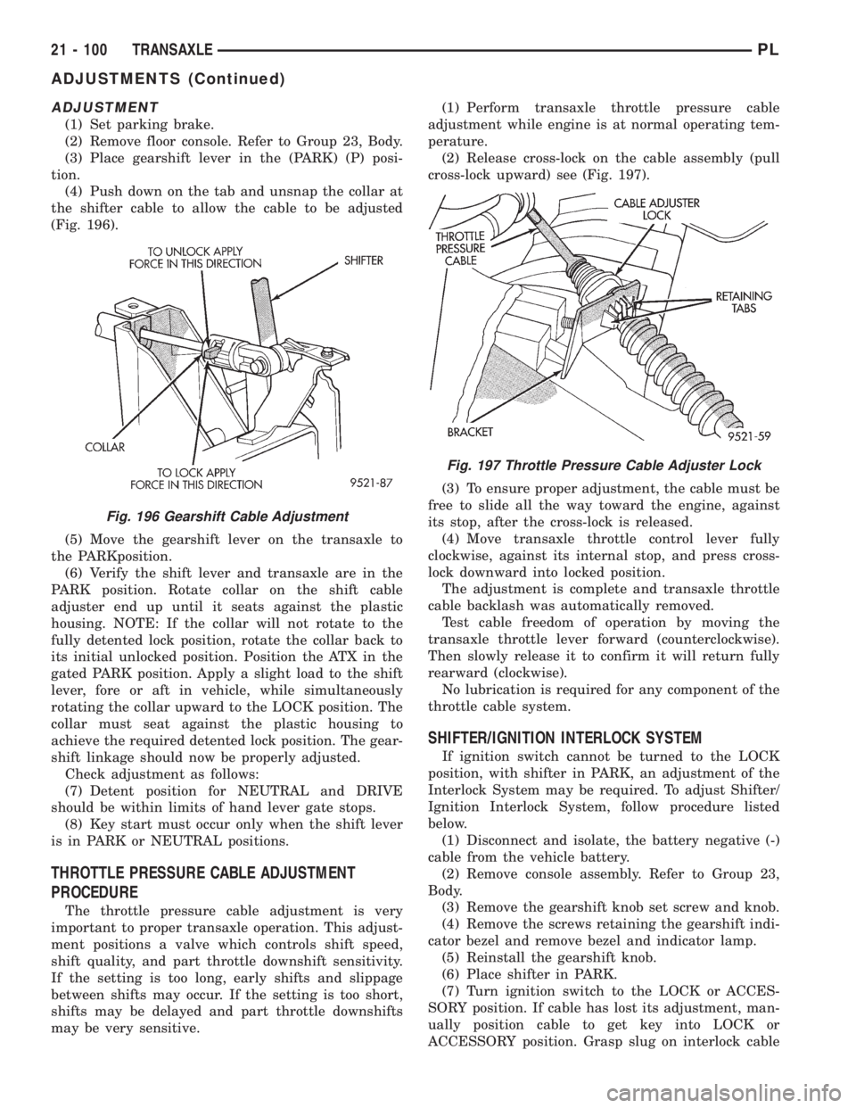
(4) Push down on the tab and unsnap the collar at
the shifter cable to allow the cable to be adjusted
(Fig. 196).
(5) Move the gearshift lever on the transaxle to
the PARKposition.
(6) Verify the shift lever and transaxle are in the
PARK position. Rotate collar on the shift cable
adjuster end up until it seats against the plastic
housing. NOTE: If the collar will not rotate to the
fully detented lock position, rotate the collar back to
its initial unlocked position. Position the ATX in the
gated PARK position. Apply a slight load to the shift
lever, fore or aft in vehicle, while simultaneously
rotating the collar upward to the LOCK position. The
collar must seat against the plastic housing to
achieve the required detented lock position. The gear-
shift linkage should now be properly adjusted.
Check adjustment as follows:
(7) Detent position for NEUTRAL and DRIVE
should be within limits of hand lever gate stops.
(8) Key start must occur only when the shift lever
is in PARK or NEUTRAL positions.
THROTTLE PRESSURE CABLE ADJUSTMENT
PROCEDURE
The throttle pressure cable adjustment is very
important to proper transaxle operation. This adjust-
ment positions a valve which controls shift speed,
shift quality, and part throttle downshift sensitivity.
If the setting is too long, early shifts and slippage
between shifts may occur. If the setting is too short,
shifts may be delayed and part throttle downshifts
may be very sensitive.(1) Perform transaxle throttle pressure cable
adjustment while engine is at normal operating tem-
perature.
(2) Release cross-lock on the cable assembly (pull
cross-lock upward) see (Fig. 197).
(3) To ensure proper adjustment, the cable must be
free to slide all the way toward the engine, against
its stop, after the cross-lock is released.
(4) Move transaxle throttle control lever fully
clockwise, against its internal stop, and press cross-
lock downward into locked position.
The adjustment is complete and transaxle throttle
cable backlash was automatically removed.
Test cable freedom of operation by moving the
transaxle throttle lever forward (counterclockwise).
Then slowly release it to confirm it will return fully
rearward (clockwise).
No lubrication is required for any component of the
throttle cable system.
SHIFTER/IGNITION INTERLOCK SYSTEM
If ignition switch cannot be turned to the LOCK
position, with shifter in PARK, an adjustment of the
Interlock System may be required. To adjust Shifter/
Ignition Interlock System, follow procedure listed
below.
(1) Disconnect and isolate, the battery negative (-)
cable from the vehicle battery.
(2) Remove console assembly. Refer to Group 23,
Body.
(3) Remove the gearshift knob set screw and knob.
(4) Remove the screws retaining the gearshift indi-
cator bezel and remove bezel and indicator lamp.
(5) Reinstall the gearshift knob.
(6) Place shifter in PARK.
(7) Turn ignition switch to the LOCK or ACCES-
SORY position. If cable has lost its adjustment, man-
ually position cable to get key into LOCK or
ACCESSORY position. Grasp slug on interlock cable
Fig. 196 Gearshift Cable Adjustment
Fig. 197 Throttle Pressure Cable Adjuster Lock
21 - 100 TRANSAXLEPL
ADJUSTMENTS (Continued)