1999 DODGE NEON fuel tank removal
[x] Cancel search: fuel tank removalPage 270 of 1200
INSTRUMENT PANEL AND SYSTEMS
CONTENTS
page page
GENERAL INFORMATION
INTRODUCTION......................... 1
DESCRIPTION AND OPERATION
DOME LAMP............................ 1
ELECTRONIC DIGITAL CLOCK.............. 1
INSTRUMENT CLUSTER................... 2
WARNING AND INDICATOR LAMPS......... 2
DIAGNOSIS AND TESTING
AIRBAG WARNING SYSTEM............... 2
BRAKE SYSTEM WARNING LAMP TEST...... 2
FOG LAMP SWITCH TEST................. 2
FUEL TANK SENDING UNIT TEST........... 3
HEADLAMP SWITCH TEST................. 3
HEATER A/C BLOWER SWITCH TEST........ 3
HEATER BLOWER SWITCH TEST............ 3
INDIVIDUAL GAUGE INOPERATIVE.......... 4
INSTRUMENT PANEL AND COMPONENTS.... 4
LOW OIL PRESSURE WARNING LAMP TEST . . 4
MULTIPLE GAUGE INOPERATIVE TEST....... 4
SEAT BELT REMINDER SYSTEM TEST....... 6
SENDING UNIT......................... 6
SERVICE ENGINE SOON INDICATOR......... 6
VEHICLE SPEED SENSOR TEST............. 6
REMOVAL AND INSTALLATION
ASH RECEIVER RETAINER AND LAMP....... 6
CENTER BEZEL.......................... 6
CIGAR LIGHTER RECEPTACLE.............. 6
CLUSTER LAMP......................... 7
CLUSTER PRINTED CIRCUIT BOARD........ 7CLUSTER.............................. 7
DOME LENS/LAMP....................... 8
FLOOR CONSOLE........................ 8
GAUGE................................ 8
GLOVE BOX DOOR/BIN................... 8
GLOVE BOX SWITCH/LAMP................ 9
HEADLAMP SWITCH..................... 9
HEATER A/C CONTROL BLOWER SWITCH . . . 10
HEATER A/C CONTROL LAMP............ 10
HEATER A/C CONTROL................... 9
HEATER CONTROL BLOWER SWITCH....... 10
IGNITION KEY LAMP.................... 10
INSTRUMENT PANEL.................... 10
LEFT TRIM PANEL...................... 10
ODOMETER............................ 10
RADIO................................ 12
REAR WINDOW DEFOGGER AND/OR FOG
LAMP SWITCH....................... 12
RIGHT TRIM PANEL..................... 12
SHIFTER KNOB......................... 13
STEERING COLUMN COVER LINER......... 13
STEERING COLUMN COVER.............. 13
STEERING COLUMN SHROUDS............ 13
TOP COVER AND CLUSTER BEZEL
REMOVAL........................... 14
TRANSMISSION RANGE INDICATOR LAMP . . 14
TRUNK LAMP/LENS..................... 14
VEHICLE SPEED SENSOR................ 14
GENERAL INFORMATION
INTRODUCTION
The purpose of the dash gauges and indicator
lamps is to keep the driver informed about the oper-
ating condition of the vehicle. If an abnormal condi-
tion occurs, the driver is informed by indicator lamp.
The driver can seek service before damage occurs.
Indicator lamps use ON/OFF switch functions for
operation, while gauges use a sending unit or sensor.
DESCRIPTION AND OPERATION
DOME LAMP
The Dome Lamp operates when a door is open or
when the headlamp switch is placed in courtesy posi-
tion.
ELECTRONIC DIGITAL CLOCK
The electronic digital clock is in the radio. The
clock and radio each use the display panel built into
the radio. A digital readout indicates the time in
hours and minutes whenever the ignition switch is in
the ON or ACC position.
PLINSTRUMENT PANEL AND SYSTEMS 8E - 1
Page 272 of 1200
FUEL TANK SENDING UNIT TEST
Refer to Group 14, Fuel for test procedures.
HEADLAMP SWITCH TEST
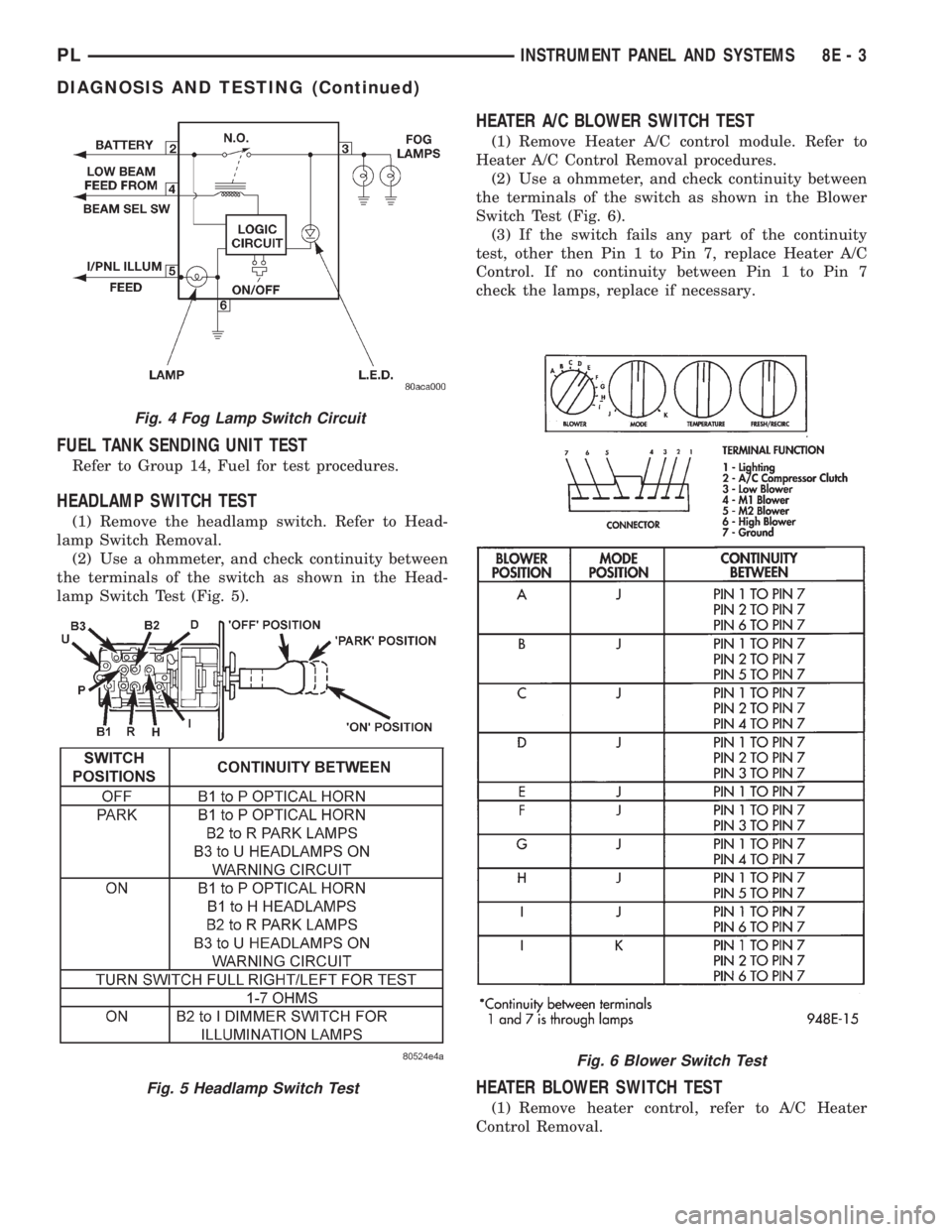
(1) Remove the headlamp switch. Refer to Head-
lamp Switch Removal.
(2) Use a ohmmeter, and check continuity between
the terminals of the switch as shown in the Head-
lamp Switch Test (Fig. 5).
HEATER A/C BLOWER SWITCH TEST
(1) Remove Heater A/C control module. Refer to
Heater A/C Control Removal procedures.
(2) Use a ohmmeter, and check continuity between
the terminals of the switch as shown in the Blower
Switch Test (Fig. 6).
(3) If the switch fails any part of the continuity
test, other then Pin 1 to Pin 7, replace Heater A/C
Control. If no continuity between Pin 1 to Pin 7
check the lamps, replace if necessary.
HEATER BLOWER SWITCH TEST
(1) Remove heater control, refer to A/C Heater
Control Removal.
Fig. 4 Fog Lamp Switch Circuit
Fig. 5 Headlamp Switch Test
Fig. 6 Blower Switch Test
PLINSTRUMENT PANEL AND SYSTEMS 8E - 3
DIAGNOSIS AND TESTING (Continued)
Page 844 of 1200
FUEL DELIVERY SYSTEM
INDEX
page page
DESCRIPTION AND OPERATION
ELECTRIC FUEL PUMP.................... 4
FUEL DELIVERY SYSTEM.................. 3
FUEL FILTER/FUEL PRESSURE REGULATOR . . . 4
FUEL GAUGE SENDING UNIT............... 4
FUEL INJECTORS........................ 5
FUEL PUMP MODULE..................... 3
FUEL RAIL.............................. 4
FUEL TANK............................. 4
PRESSURE-VACUUM FILLER CAP........... 5
QUICK-CONNECT FITTINGS................ 5
ROLLOVER VALVES...................... 5
DIAGNOSIS AND TESTING
FUEL INJECTORS........................ 8
FUEL LEVEL SENSOR..................... 6
FUEL PUMP PRESSURE TEST.............. 6
SERVICE PROCEDURES
DRAINING FUEL TANK.................... 10
FUEL SYSTEM PRESSURE RELEASE
PROCEDURE......................... 10HOSES AND CLAMPS.................... 10
QUICK-CONNECT FITTINGS............... 11
REMOVAL AND INSTALLATION
ACCELERATOR PEDAL................... 17
AUTOMATIC SHUTDOWN RELAY........... 11
FUEL FILLER NECK...................... 16
FUEL FILLER TUBE ROLLOVER VALVE....... 16
FUEL FILTER / PRESSURE REGULATOR..... 12
FUEL INJECTORS....................... 14
FUEL LEVEL SENSOR.................... 13
FUEL PUMP INLET STRAINER............. 13
FUEL PUMP MODULE.................... 11
FUEL PUMP RELAY...................... 11
FUEL TANK............................ 15
THROTTLE CABLEÐAUTOMATIC
TRANSMISSION....................... 18
THROTTLE CABLEÐMANUAL TRANSMISSION . 17
SPECIFICATIONS
FUEL TANK CAPACITY................... 19
TORQUE.............................. 19
DESCRIPTION AND OPERATION
FUEL DELIVERY SYSTEM
The fuel delivery system consists of: the electric
fuel pump, fuel filter/fuel pressure regulator, fuel
tubes/lines/hoses, fuel rail, fuel injectors, fuel tank,
accelerator pedal and throttle cable.
A fuel return system is used on all models (all
engines). Fuel is returned through the fuel pump
module and back into the fuel tank through the fuel
filter/fuel pressure regulator. A separate fuel return
line from the engine to the tank is no longer used
with any engine.
The fuel tank assembly consists of: the fuel tank,
filler tube, fuel gauge sending unit/electric fuel pump
module, a pressure relief/rollover valve and a pres-
sure-vacuum filler cap.
Also to be considered part of the fuel system is the
evaporation control system. This is designed to
reduce the emission of fuel vapors into the atmo-
sphere. The description and function of the Evapora-
tive Control System is found in Group 25, Emission
Control Systems.
FUEL PUMP MODULE
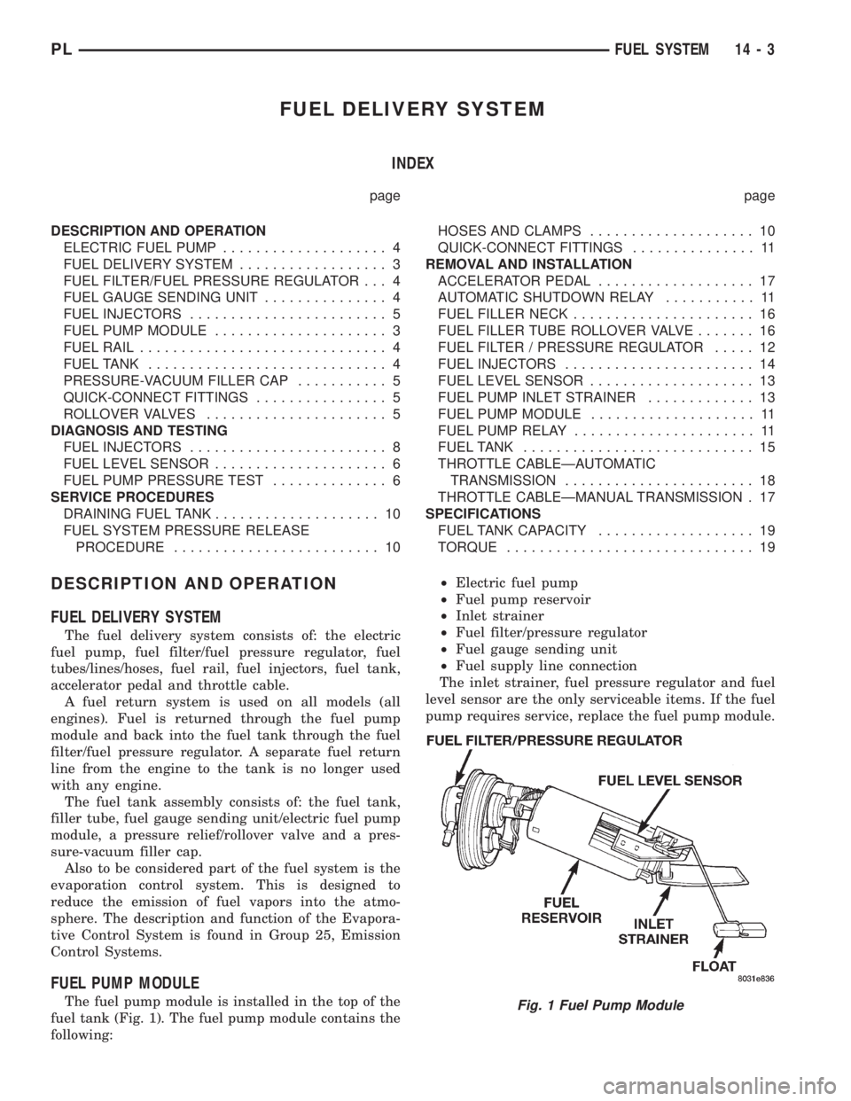
The fuel pump module is installed in the top of the
fuel tank (Fig. 1). The fuel pump module contains the
following:²Electric fuel pump
²Fuel pump reservoir
²Inlet strainer
²Fuel filter/pressure regulator
²Fuel gauge sending unit
²Fuel supply line connection
The inlet strainer, fuel pressure regulator and fuel
level sensor are the only serviceable items. If the fuel
pump requires service, replace the fuel pump module.Fig. 1 Fuel Pump Module
PLFUEL SYSTEM 14 - 3
Page 846 of 1200
FUEL INJECTORS
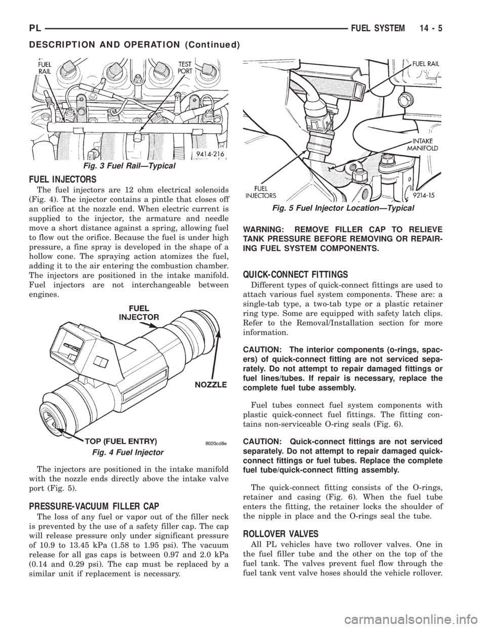
The fuel injectors are 12 ohm electrical solenoids
(Fig. 4). The injector contains a pintle that closes off
an orifice at the nozzle end. When electric current is
supplied to the injector, the armature and needle
move a short distance against a spring, allowing fuel
to flow out the orifice. Because the fuel is under high
pressure, a fine spray is developed in the shape of a
hollow cone. The spraying action atomizes the fuel,
adding it to the air entering the combustion chamber.
The injectors are positioned in the intake manifold.
Fuel injectors are not interchangeable between
engines.
The injectors are positioned in the intake manifold
with the nozzle ends directly above the intake valve
port (Fig. 5).
PRESSURE-VACUUM FILLER CAP
The loss of any fuel or vapor out of the filler neck
is prevented by the use of a safety filler cap. The cap
will release pressure only under significant pressure
of 10.9 to 13.45 kPa (1.58 to 1.95 psi). The vacuum
release for all gas caps is between 0.97 and 2.0 kPa
(0.14 and 0.29 psi). The cap must be replaced by a
similar unit if replacement is necessary.WARNING: REMOVE FILLER CAP TO RELIEVE
TANK PRESSURE BEFORE REMOVING OR REPAIR-
ING FUEL SYSTEM COMPONENTS.
QUICK-CONNECT FITTINGS
Different types of quick-connect fittings are used to
attach various fuel system components. These are: a
single-tab type, a two-tab type or a plastic retainer
ring type. Some are equipped with safety latch clips.
Refer to the Removal/Installation section for more
information.
CAUTION: The interior components (o-rings, spac-
ers) of quick-connect fitting are not serviced sepa-
rately. Do not attempt to repair damaged fittings or
fuel lines/tubes. If repair is necessary, replace the
complete fuel tube assembly.
Fuel tubes connect fuel system components with
plastic quick-connect fuel fittings. The fitting con-
tains non-serviceable O-ring seals (Fig. 6).
CAUTION: Quick-connect fittings are not serviced
separately. Do not attempt to repair damaged quick-
connect fittings or fuel tubes. Replace the complete
fuel tube/quick-connect fitting assembly.
The quick-connect fitting consists of the O-rings,
retainer and casing (Fig. 6). When the fuel tube
enters the fitting, the retainer locks the shoulder of
the nipple in place and the O-rings seal the tube.
ROLLOVER VALVES
All PL vehicles have two rollover valves. One in
the fuel filler tube and the other on the top of the
fuel tank. The valves prevent fuel flow through the
fuel tank vent valve hoses should the vehicle rollover.
Fig. 3 Fuel RailÐTypical
Fig. 4 Fuel Injector
Fig. 5 Fuel Injector LocationÐTypical
PLFUEL SYSTEM 14 - 5
DESCRIPTION AND OPERATION (Continued)
Page 852 of 1200
The hose clamps have rolled edges to prevent the
clamp from cutting into the hose. Only use clamps
that are original equipment or equivalent. Other
types of clamps may cut into the hoses and cause
high pressure fuel leaks. Tighten hose clamps to 1
N´m (10 in. lbs.) torque.
QUICK-CONNECT FITTINGS
REMOVAL
When disconnecting a quick-connect fitting, the
retainer will remain on the fuel tube nipple.
WARNING: RELEASE FUEL SYSTEM PRESSURE
BEFORE DISCONNECTING A QUICK-CONNECT FIT-
TINGS. REFER TO THE FUEL PRESSURE RELEASE
PROCEDURE.
(1) Disconnect negative cable from battery.
(2) Perform Fuel Pressure Release Procedure.
Refer to the Fuel Pressure Release Procedure in this
section.
(3) Squeeze retainer tabs together and pull fuel
tube/quick-connect fitting assembly off of fuel tube
nipple. The retainer will remain on fuel tube.
INSTALLATION
CAUTION: Never install a quick-connect fitting
without the retainer being either on the fuel tube or
already in the quick-connect fitting. In either case,
ensure the retainer locks securely into the quick-
connect fitting by firmly pulling on fuel tube and fit-
ting to ensure it is secured.
(1) Using a clean lint free cloth, clean the fuel tube
nipple and retainer.
(2) Prior to connecting the fitting to the fuel tube,
coat the fuel tube nipple with clean 30 weight engine
oil.
(3) Push the quick-connect fitting over the fuel
tube until theretainer seats and a click is heard.
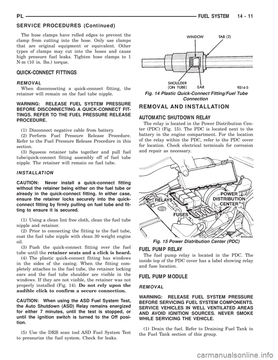
(4) The plastic quick-connect fitting has windows
in the sides of the casing. When the fitting com-
pletely attaches to the fuel tube, the retainer locking
ears and the fuel tube shoulder are visible in the
windows. If they are not visible, the retainer was not
properly installed (Fig. 14).Do not rely upon the
audible click to confirm a secure connection.
CAUTION: When using the ASD Fuel System Test,
the Auto Shutdown (ASD) Relay remains energized
for either 7 minutes, until the test is stopped, or
until the ignition switch is turned to the Off posi-
tion.
(5) Use the DRB scan tool ASD Fuel System Test
to pressurize the fuel system. Check for leaks.
REMOVAL AND INSTALLATION
AUTOMATIC SHUTDOWN RELAY
The relay is located in the Power Distribution Cen-
ter (PDC) (Fig. 15). The PDC is located next to the
battery in the engine compartment. For the location
of the relay within the PDC, refer to the PDC cover
for location. Check electrical terminals for corrosion
and repair as necessary.
FUEL PUMP RELAY
The fuel pump relay is located in the PDC. The
inside top of the PDC cover has a label showing relay
and fuse location.
FUEL PUMP MODULE
REMOVAL
WARNING: RELEASE FUEL SYSTEM PRESSURE
BEFORE SERVICING FUEL SYSTEM COMPONENTS.
SERVICE VEHICLES IN WELL VENTILATED AREAS
AND AVOID IGNITION SOURCES. NEVER SMOKE
WHILE SERVICING THE VEHICLE.
(1) Drain the fuel. Refer to Draining Fuel Tank in
the Fuel Tank section of this group.
Fig. 14 Plastic Quick-Connect Fitting/Fuel Tube
Connection
Fig. 15 Power Distribution Center (PDC)
PLFUEL SYSTEM 14 - 11
SERVICE PROCEDURES (Continued)
Page 853 of 1200
WARNING: THE FUEL RESERVOIR OF THE FUEL
PUMP MODULE DOES NOT EMPTY OUT WHEN THE
TANK IS DRAINED. THE FUEL IN THE RESERVOIR
WILL SPILL OUT WHEN THE MODULE IS
REMOVED.
(2) Disconnect fuel line from fuel pump module by
depressing quick connect retainers with thumb and
fore finger.
(3) Slide fuel pump module electrical connecter
lock to unlock.
(4) Disconnect the electrical connection from the
fuel pump module, by pushing down on connector
retainer and pulling connector off of module.
(5) Use a transmission jack to support the fuel
tank. remove bolts from fuel tank straps.
(6) Lower tank slightly.
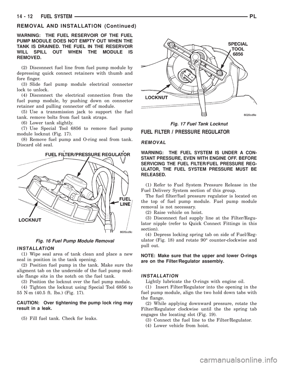
(7) Use Special Tool 6856 to remove fuel pump
module locknut (Fig. 17).
(8) Remove fuel pump and O-ring seal from tank.
Discard old seal.
INSTALLATION
(1) Wipe seal area of tank clean and place a new
seal in position in the tank opening.
(2) Position fuel pump in the tank. Make sure the
aligment tab on the underside of the fuel pump mod-
ule flange sits in the notch on the fuel tank.
(3)
Position the locknut over the fuel pump module.
(4) Tighten the locknut using Special Tool 6856 to
55 N´m (40.5 ft. lbs.) (Fig. 17).
CAUTION: Over tightening the pump lock ring may
result in a leak.
(5) Fill fuel tank. Check for leaks.
FUEL FILTER / PRESSURE REGULATOR
REMOVAL
WARNING: THE FUEL SYSTEM IS UNDER A CON-
STANT PRESSURE, EVEN WITH ENGINE OFF. BEFORE
SERVICING THE FUEL FILTER/FUEL PRESSURE REG-
ULATOR, THE FUEL SYSTEM PRESSURE MUST BE
RELEASED.
(1) Refer to Fuel System Pressure Release in the
Fuel Delivery System section of this group.
The fuel filter/fuel pressure regulator is located on
the top of fuel pump module. Fuel pump module
removal is not necessary.
(2) Raise vehicle on hoist.
(3) Disconnect fuel supply line at the Filter/Regu-
lator nipple (refer to Quick Connect Fittings in this
section).
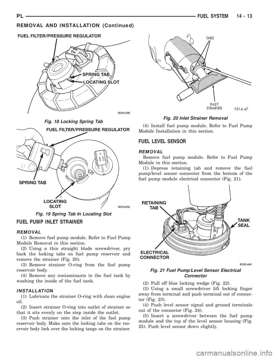
(4) Depress locking spring tab on side of Fuel/Reg-
ulator (Fig. 18) and rotate 90É counter-clockwise and
pull out.
NOTE: Make sure that the upper and lower O-rings
are on the Filter/Regulator assembly.
INSTALLATION
Lightly lubricate the O-rings with engine oil.
(1) Insert Filter/Regulator into the opening in the
fuel pump module, align the two hold down tabs with
the flange.
(2) While applying downward pressure, rotate the
Filter/Regulator clockwise until the the spring tab
engages the locating slot (Fig. 19).
(3) Connect the fuel line to the Filter/Regulator.
(4) Lower vehicle from hoist.
Fig. 16 Fuel Pump Module Removal
Fig. 17 Fuel Tank Locknut
14 - 12 FUEL SYSTEMPL
REMOVAL AND INSTALLATION (Continued)
Page 854 of 1200
FUEL PUMP INLET STRAINER
REMOVAL
(1) Remove fuel pump module. Refer to Fuel Pump
Module Removal in this section.
(2) Using a thin straight blade screwdriver, pry
back the locking tabs on fuel pump reservoir and
remove the strainer (Fig. 20).
(3) Remove strainer O-ring from the fuel pump
reservoir body.
(4) Remove any contaminants in the fuel tank by
washing the inside of the fuel tank.
INSTALLATION
(1) Lubricate the strainer O-ring with clean engine
oil.
(2) Insert strainer O-ring into outlet of strainer so
that it sits evenly on the step inside the outlet.
(3) P
ush strainer onto the inlet of the fuel pump
reservoir body. Make sure the locking tabs on the res-
ervoir body lock over the locking tangs on the strainer.
(4) Install fuel pump module. Refer to Fuel Pump
Module Installation in this section.
FUEL LEVEL SENSOR
REMOVAL
Remove fuel pump module. Refer to Fuel Pump
Module in this section.
(1) Depress retaining tab and remove the fuel
pump/level sensor connector from the bottom of the
fuel pump module electrical connector (Fig. 21).
(2) Pull off blue locking wedge (Fig. 22).
(3) Using a small screwdriver lift locking finger
away from terminal and push terminal out of connec-
tor (Fig. 23).
(4) Push level sensor signal and ground terminals
out of the connector (Fig. 24).
(5) Insert a screwdriver between the fuel pump
module and the top of the level sensor housing (Fig.
25). Push level sensor down slightly.
Fig. 18 Locking Spring Tab
Fig. 19 Spring Tab In Locating Slot
Fig. 20 Inlet Strainer Removal
Fig. 21 Fuel Pump/Level Sensor Electrical
Connector
PLFUEL SYSTEM 14 - 13
REMOVAL AND INSTALLATION (Continued)
Page 856 of 1200
(5) Remove fuel rail mounting screws.
(6) Lift rail off of intake manifold. Cover the fuel
injector openings in the intake manifold.
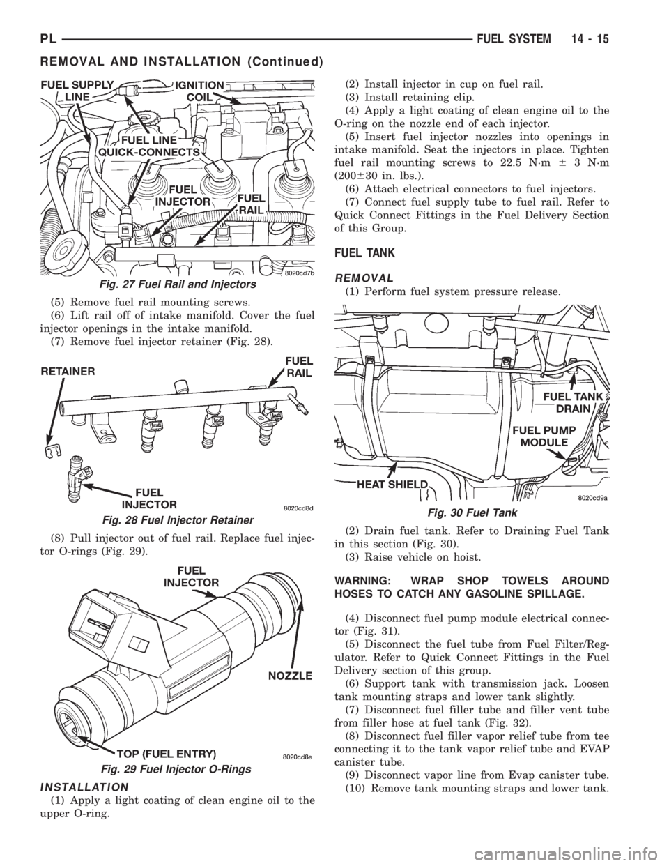
(7) Remove fuel injector retainer (Fig. 28).
(8) Pull injector out of fuel rail. Replace fuel injec-
tor O-rings (Fig. 29).
INSTALLATION
(1) Apply a light coating of clean engine oil to the
upper O-ring.(2) Install injector in cup on fuel rail.
(3) Install retaining clip.
(4) Apply a light coating of clean engine oil to the
O-ring on the nozzle end of each injector.
(5) Insert fuel injector nozzles into openings in
intake manifold. Seat the injectors in place. Tighten
fuel rail mounting screws to 22.5 N´m63 N´m
(200630 in. lbs.).
(6) Attach electrical connectors to fuel injectors.
(7) Connect fuel supply tube to fuel rail. Refer to
Quick Connect Fittings in the Fuel Delivery Section
of this Group.
FUEL TANK
REMOVAL
(1) Perform fuel system pressure release.
(2) Drain fuel tank. Refer to Draining Fuel Tank
in this section (Fig. 30).
(3) Raise vehicle on hoist.
WARNING: WRAP SHOP TOWELS AROUND
HOSES TO CATCH ANY GASOLINE SPILLAGE.
(4) Disconnect fuel pump module electrical connec-
tor (Fig. 31).
(5) Disconnect the fuel tube from Fuel Filter/Reg-
ulator. Refer to Quick Connect Fittings in the Fuel
Delivery section of this group.
(6) Support tank with transmission jack. Loosen
tank mounting straps and lower tank slightly.
(7) Disconnect fuel filler tube and filler vent tube
from filler hose at fuel tank (Fig. 32).
(8) Disconnect fuel filler vapor relief tube from tee
connecting it to the tank vapor relief tube and EVAP
canister tube.
(9) Disconnect vapor line from Evap canister tube.
(10) Remove tank mounting straps and lower tank.Fig. 27 Fuel Rail and Injectors
Fig. 28 Fuel Injector Retainer
Fig. 29 Fuel Injector O-Rings
Fig. 30 Fuel Tank
PLFUEL SYSTEM 14 - 15
REMOVAL AND INSTALLATION (Continued)