Page 857 of 1200

INSTALLATION
(1) Position fuel tank on transmission jack.
(2) Raise tank into position. Connect fuel filler
tube tank inlet nipple.
(3) Tighten fuel tank strap nuts to 22.5 N´m (200
in. lbs.) torque. Remove transmission jack. Ensure
straps are not twisted or bent.
(4) Attach fuel tubes to pump module and chassis
fuel tube. Refer to Quick Connect Fittings in the Fuel
Delivery section of this Group.
(5) Connect fuel vapor tube to tee, then to Evap
canister tube.
(6)
Attach electrical connector to fuel pump module.
(7) Lower vehicle.
(8) Fill fuel tank, install filler cap, and connect
battery cable.
CAUTION: When using the ASD Fuel System Test, the
Auto Shutdown (ASD) Relay remains energized for
either 7 minutes, until the test is stopped, or until the
ignition switch is turned to the Off position.
(9) Use the DRB scan tool ASD Fuel System Test
to pressurize the fuel system. Check for leaks.
FUEL FILLER NECK
REMOVAL
(1) Loosen fuel filler tube cap.
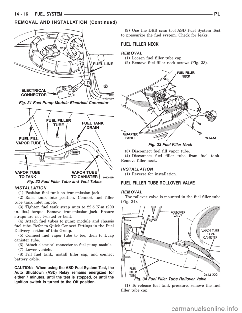
(2) Remove fuel filler neck screws (Fig. 33).
(3) Disconnect fuel fill vapor tube.
(4) Disconnect fuel filler tube from fuel tank.
Remove filler neck.
INSTALLATION
(1) Reverse for installation.
FUEL FILLER TUBE ROLLOVER VALVE
REMOVAL
The rollover valve is mounted in the fuel filler tube
(Fig. 34).
(1) To release fuel tank pressure, remove the fuel
filler tube cap.
Fig. 31 Fuel Pump Module Electrical Connector
Fig. 32 Fuel Filler Tube and Vent Tubes
Fig. 33 Fuel Filler Neck
Fig. 34 Fuel Filler Tube Rollover Valve
14 - 16 FUEL SYSTEMPL
REMOVAL AND INSTALLATION (Continued)
Page 860 of 1200

(6) From the engine compartment, pull the throttle
cable out of the dash panel grommet. The grommet
should remain in the dash panel.
INSTALLATION
(1) From the engine compartment, push the hous-
ing end fitting into the dash panel grommet.
(2) Install cable housing (throttle body end) into
the cable mounting bracket on the engine.
(3) From inside the vehicle, hold up pedal and feed
throttle cable core wire through hole in upper end of
the pedal shaft. Install cable retainer (Fig. 36).
(4) Install cable retainer clip.
(5) From the engine compartment, rotate the
throttle lever forward to the wide open position and
install cable clasp (Fig. 41).
(6) Install throttle control shield (Fig. 37). Tighten
to 5.6 N´m (50 in. lbs.).
SPECIFICATIONS
TORQUE
DESCRIPTION TORQUE
Accelerator Pedal to Dash Nuts...........12N´m
(105 in. lbs.)
Fuel Pump Module Locknut.....55N´m(40ft.lbs.)
Fuel Tank Strap Bolts.......22.5 N´m (200 in. lbs.)
Fuel Rail Bolts..............23N´m(195 in. lbs.)
Ignition Coil Mounting Bolts....11N´m(95in.lbs.)
Intake Manifold Bolts..........11N´m(95in.lbs.)
Throttle Control Shield........5.6 N´m (50 in. lbs.)
FUEL TANK CAPACITY
Vehicle Liters U.S. Gallons
PL 47 12.5
Nominal refill capacities are shown. A variation may be
observed from vehicle to vehicle due to manufacturing
tolerance and refill procedure.
PLFUEL SYSTEM 14 - 19
REMOVAL AND INSTALLATION (Continued)
Page 1174 of 1200

EVAPORATIVE EMISSION CONTROLS
INDEX
page page
DESCRIPTION AND OPERATION
DUTY CYCLE EVAP PURGE SOLENOID VALVE . 11
EVAP CANISTER........................ 11
EVAPORATION CONTROL SYSTEM.......... 11
LEAK DETECTION PUMP................. 12
POSITIVE CRANKCASE VENTILATION (PCV)
SYSTEMS............................ 12
PRESSURE-VACUUM FILLER CAP.......... 12
ROLLOVER VALVE....................... 11VEHICLE EMISSION CONTROL INFORMATION
LABEL............................... 13
DIAGNOSIS AND TESTING
LEAK DETECTION PUMP................. 14
PCV VALVE TEST....................... 14
VACUUM SCHEMATIC.................... 14
REMOVAL AND INSTALLATION
LEAK DETECTION PUMP REPLACEMENT.... 17
DESCRIPTION AND OPERATION
EVAPORATION CONTROL SYSTEM
The evaporation control system prevents the emis-
sion of fuel tank vapors into the atmosphere. When
fuel evaporates in the fuel tank, the vapors pass
through vent hoses or tubes to a charcoal filled evap-
orative canister. The canister temporarily holds the
vapors. The Powertrain Control Module (PCM) allows
intake manifold vacuum to draw vapors into the com-
bustion chambers during certain operating condi-
tions.
All engines use a proportional purge system. The
PCM controls vapor flow by operating the purge sole-
noid. Refer to Proportional Purge Solenoid in this
section.
NOTE: The evaporative system uses specially man-
ufactured hoses. If they need replacement, only use
fuel resistant hose.
ROLLOVER VALVE
All vehicles have a rollover valve. The valve also
prevents fuel flow through the fuel tank vent valve
hoses should the vehicle rollover. All vehicles pass a
360É rollover.
The charcoal filled evaporative canister stores the
vapors. The rollover valve is not a serviceable item.
EVAP CANISTER
All vehicles use a sealed, maintenance free, evapo-
rative (EVAP) canister. Fuel tank pressure vents into
the canister. The canister temporarily holds the fuel
vapors until intake manifold vacuum draws them
into the combustion chamber. The PCM purges the
canister through the duty cycle EVAP purge solenoid.
The PCM purges the canister at predetermined inter-
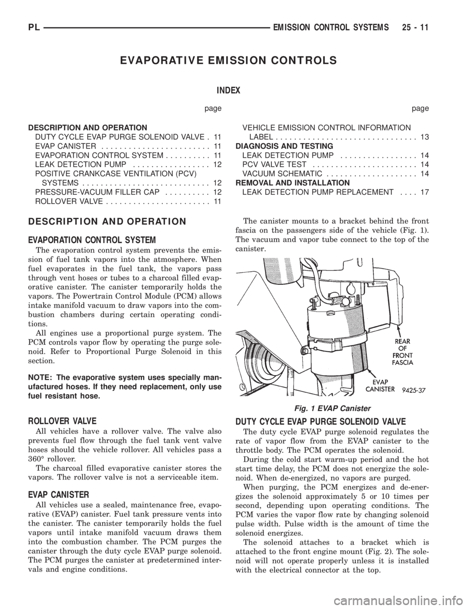
vals and engine conditions.The canister mounts to a bracket behind the front
fascia on the passengers side of the vehicle (Fig. 1).
The vacuum and vapor tube connect to the top of the
canister.
DUTY CYCLE EVAP PURGE SOLENOID VALVE
The duty cycle EVAP purge solenoid regulates the
rate of vapor flow from the EVAP canister to the
throttle body. The PCM operates the solenoid.
During the cold start warm-up period and the hot
start time delay, the PCM does not energize the sole-
noid. When de-energized, no vapors are purged.
When purging, the PCM energizes and de-ener-
gizes the solenoid approximately 5 or 10 times per
second, depending upon operating conditions. The
PCM varies the vapor flow rate by changing solenoid
pulse width. Pulse width is the amount of time the
solenoid energizes.
The solenoid attaches to a bracket which is
attached to the front engine mount (Fig. 2). The sole-
noid will not operate properly unless it is installed
with the electrical connector at the top.
Fig. 1 EVAP Canister
PLEMISSION CONTROL SYSTEMS 25 - 11