1999 DODGE NEON parking brake
[x] Cancel search: parking brakePage 871 of 1200
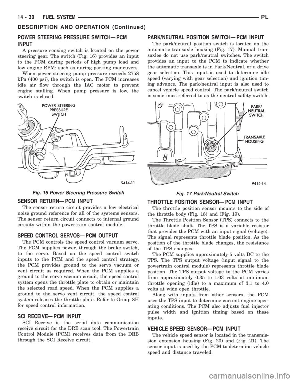
POWER STEERING PRESSURE SWITCHÐPCM
INPUT
A pressure sensing switch is located on the power
steering gear. The switch (Fig. 16) provides an input
to the PCM during periods of high pump load and
low engine RPM; such as during parking maneuvers.
When power steering pump pressure exceeds 2758
kPa (400 psi), the switch is open. The PCM increases
idle air flow through the IAC motor to prevent
engine stalling. When pump pressure is low, the
switch is closed.
SENSOR RETURNÐPCM INPUT
The sensor return circuit provides a low electrical
noise ground reference for all of the systems sensors.
The sensor return circuit connects to internal ground
circuits within the powertrain control module.
SPEED CONTROL SERVOSÐPCM OUTPUT
The PCM controls the speed control vacuum servo.
The PCM supplies power, through the brake switch,
to the servo. Based on the speed control switch
inputs to the PCM and the speed control strategy,
the PCM provides ground to the servo vacuum or
vent circuit as required. When the PCM supplies a
ground to the servo vacuum circuit, the speed control
system opens the throttle plate to obtain or maintain
the selected road speed. When the PCM supplies a
ground to the servo vent circuit, the speed control
system releases the throttle plate. Refer to Group 8H
for speed control information.
SCI RECEIVEÐPCM INPUT
SCI Receive is the serial data communication
receive circuit for the DRB scan tool. The Powertrain
Control Module (PCM) receives data from the DRB
through the SCI Receive circuit.
PARK/NEUTRAL POSITION SWITCHÐPCM INPUT
The park/neutral position switch is located on the
automatic transaxle housing (Fig. 17). Manual tran-
saxles do not use park/neutral switches. The switch
provides an input to the PCM to indicate whether
the automatic transaxle is in Park/Neutral, or a drive
gear selection. This input is used to determine idle
speed (varying with gear selection) and ignition tim-
ing advance. The park/neutral input is also used to
cancel vehicle speed control. The park/neutral switch
is sometimes referred to as the neutral safety switch.
THROTTLE POSITION SENSORÐPCM INPUT
The throttle position sensor mounts to the side of
the throttle body (Fig. 18) and (Fig. 19).
The Throttle Position Sensor (TPS) connects to the
throttle blade shaft. The TPS is a variable resistor
that provides the PCM with an input signal (voltage).
The signal represents throttle blade position. As the
position of the throttle blade changes, the resistance
of the TPS changes.
The PCM supplies approximately 5 volts DC to the
TPS. The TPS output voltage (input signal to the
powertrain control module) represents throttle blade
position. The TPS output voltage to the PCM varies
from approximately 0.35 to 1.03 volts at minimum
throttle opening (idle) to a maximum of 3.1 to 4.0
volts at wide open throttle.
Along with inputs from other sensors, the PCM
uses the TPS input to determine current engine oper-
ating conditions. The PCM also adjusts fuel injector
pulse width and ignition timing based on these
inputs.
VEHICLE SPEED SENSORÐPCM INPUT
The vehicle speed sensor is located in the transmis-
sion extension housing (Fig. 20) and (Fig. 21). The
sensor input is used by the PCM to determine vehicle
speed and distance traveled.
Fig. 16 Power Steering Pressure SwitchFig. 17 Park/Neutral Switch
14 - 30 FUEL SYSTEMPL
DESCRIPTION AND OPERATION (Continued)
Page 949 of 1200
(12) Detach cables from cable support clip in tun-
nel above exhaust catalyst.
(13) Remove shift cable assembly from vehicle.
INSTALLATION
CAUTION: Gearshift cable bushings must not be
lubricated or the bushings will swell and split.
(1) To install, reverse removal procedure. After
cables have been replaced, cable adjustment should
be checked. Refer to cable adjustment procedure in
this section.
CAUTION: Only the crossover cable is adjustable.
The selector cable does not have any adjustment
capabilities.
GEARSHIFT CROSSOVER CABLE
ADJUSTMENT
(1) Remove shift console from vehicle.
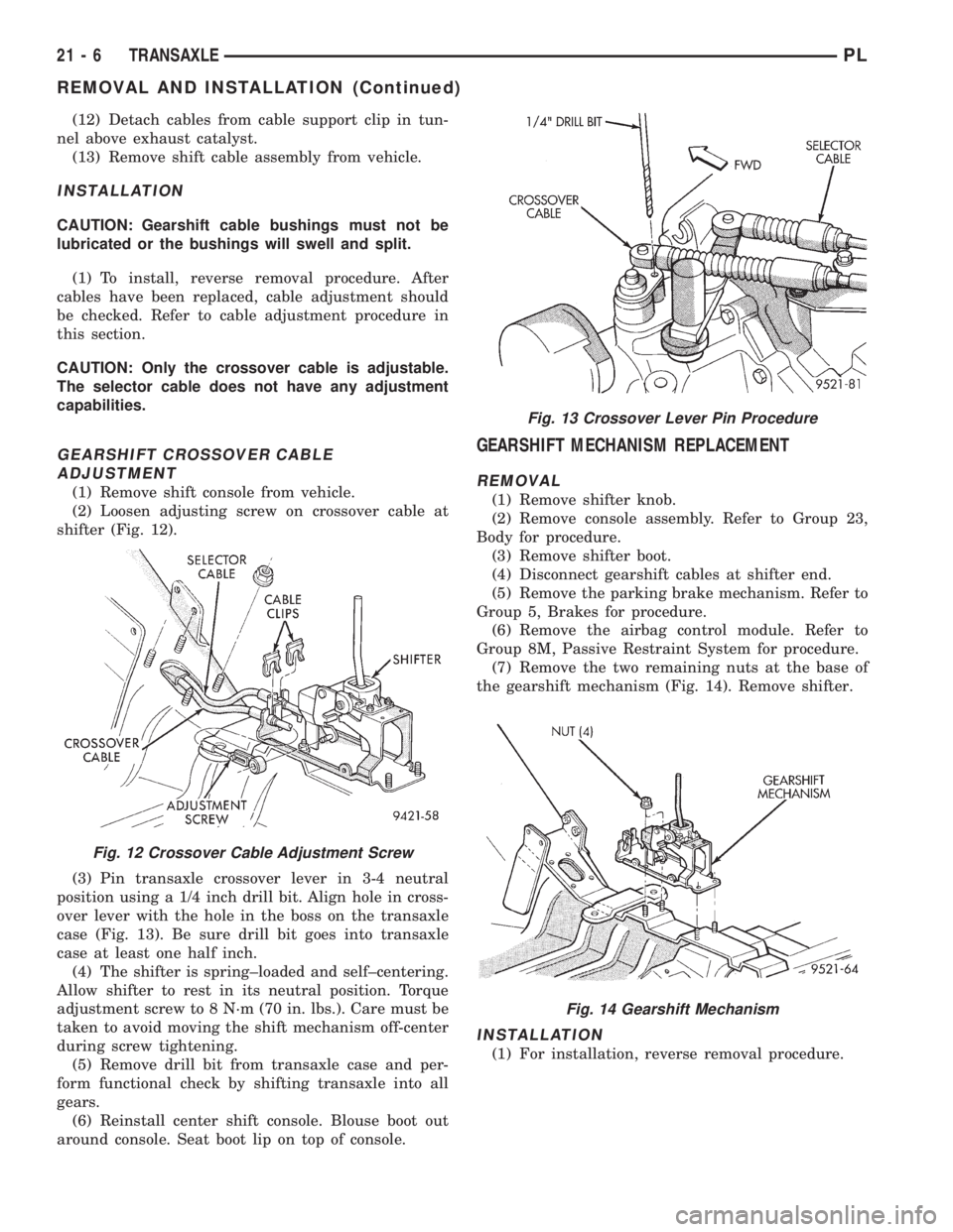
(2) Loosen adjusting screw on crossover cable at
shifter (Fig. 12).
(3) Pin transaxle crossover lever in 3-4 neutral
position using a 1/4 inch drill bit. Align hole in cross-
over lever with the hole in the boss on the transaxle
case (Fig. 13). Be sure drill bit goes into transaxle
case at least one half inch.
(4) The shifter is spring±loaded and self±centering.
Allow shifter to rest in its neutral position. Torque
adjustment screw to 8 N´m (70 in. lbs.). Care must be
taken to avoid moving the shift mechanism off-center
during screw tightening.
(5) Remove drill bit from transaxle case and per-
form functional check by shifting transaxle into all
gears.
(6) Reinstall center shift console. Blouse boot out
around console. Seat boot lip on top of console.
GEARSHIFT MECHANISM REPLACEMENT
REMOVAL
(1) Remove shifter knob.
(2) Remove console assembly. Refer to Group 23,
Body for procedure.
(3) Remove shifter boot.
(4) Disconnect gearshift cables at shifter end.
(5) Remove the parking brake mechanism. Refer to
Group 5, Brakes for procedure.
(6) Remove the airbag control module. Refer to
Group 8M, Passive Restraint System for procedure.
(7) Remove the two remaining nuts at the base of
the gearshift mechanism (Fig. 14). Remove shifter.
INSTALLATION
(1) For installation, reverse removal procedure.
Fig. 12 Crossover Cable Adjustment Screw
Fig. 13 Crossover Lever Pin Procedure
Fig. 14 Gearshift Mechanism
21 - 6 TRANSAXLEPL
REMOVAL AND INSTALLATION (Continued)
Page 999 of 1200
position should not be possible when the ignition
switch is in the LOCK or the ACCESSORY position.
(3) If the interlock system, operates in any way
other than as described above, repair of the interlock
system is required. See Adjustment and Repair pro-
cedures in this section for the required procedures.
SERVICE PROCEDURES
FLUID AND FILTER CHANGE
When the factory fill fluid is changed, only fluids
labeled MOPARtATF PLUS 3 (Automatic Transmis-
sion fluid) Type 7176 should be used.
If the transaxle is disassembled for any reason, the
fluid and filter should be changed.
30,000 MILE TRANSAXLE OIL CHANGE
When a vehicle attains 30,000 miles on its odome-
ter it is recommended that the transaxle oil be
changed. To change the oil, use the procedure that
follows:
It is recommended that a transaxle fluid exchanger
(ATF 2000+ or equivalent) be used to replace the
used fluid in the transaxle. If a fluid exchanger is not
available use a fluid suction pump (Vaculayor equiv-
alent) to draw the fluid out of the dipstick tube. If a
fluid suction pump is not available remove the oil
pan and drain the fluid.
CAUTION: Chrysler Corporation does not recom-
mend using any fluid exchanger that introduces
additives into the transaxle.
TRANSAXLE FLUID EXCHANGER METHOD
(1) To perform the transaxle fluid exchange, the
transaxle must be at operating temperature. Drive
the vehicle till it reaches full operating temperature.
(2) Verify that the fill tank on the transaxle fluid
exchanger (ATF 2000+ or equivalent) is clean and
dry.
(3) Fill the tank to the recommended fill capacity
with Mopar ATF Plus 3 Type 7176.
(4) Hookup the vehicle to the machine following
the manufacturers instructions. Perform the
exchange procedure following the instructions pro-
vided with the machine.
(5) Once machine has completed the fluid
exchange. Check the fluid level and condition and fill
to proper level with Mopar ATF Plus 3 Type 7176.
NOTE: Verify that the transaxle cooler lines are
tightened to proper specifications. Cooler line
torque specification is 2 N²m (18 in. lbs.).DIPSTICK TUBE FLUID SUCTION METHOD
(1) When performing the fluid suction method,
make sure the transaxle is at full operating temper-
ature.
(2) To perform the dipstick tube fluid suction
method, use a suitable fluid suction device (Vaculay
or equivalent).
(3) Insert the fluid suction line into the dipstick
tube.
NOTE: Verify that the suction line is inserted to the
lowest point of the transaxle oil pan. This will
ensure complete evacuation of the fluid in the pan.
(4) Follow the manufacturers recommended proce-
dure and evacuate the fluid from the transaxle.
(5) Remove the suction line from the dipstick tube.
(6) Add 4 Quarts of Mopar ATF Plus 3 Type 7176
transaxle fluid.
(7) Start the engine and allow it to idle for a min-
imum of one minute. With the parking brake applied,
press your foot on the service brake and cycle the
transaxle from park to all gear positions ending in
neutral or park.
(8) Check the transaxle fluid level and add an
appropriate amount to bring the transaxle fluid level
to 3mm (1/8 in.) below the ADD mark on the dip-
stick.
(9) Recheck the fluid level after the transaxle is at
normal operating temperature. The level should be in
the HOT range.
TRANSAXLE OIL PAN DROP METHOD
This procedure involves removing the transaxle oil
pan to drain the transaxle fluid.
(1) Bring the vehicle up to normal operating tem-
perature. Drive the vehicle a minimum of 10 miles.
(2) Raise the vehicle on the hoist.
(3) Loosen the transaxle oil pan and drain the
fluid into a suitable container.
(4) Remove the pan and clean all sealant from the
pan and transaxle mating surfaces. Clean the mag-
net and the inside of the pan.
(5) Apply a 1/8 inch bead of Mopar RTV Sealant to
the mounting flange of the transaxle oil pan. Apply
RTV Sealant to the underside of the attaching bolts.
Attach the oil pan to the transaxle. Tighten the bolts
to 19 N²m (165 in. lbs.).
(6) Lower the vehicle and add 4 Quarts of Mopar
ATF Plus 3 Type 7176 transaxle fluid.
(7) Start the engine and allow it to idle for a min-
imum of one minute. With the parking brake applied,
press your foot on the service brake and cycle the
transaxle from park to all gear positions ending in
neutral or park.
(8) Check the transaxle fluid level and add an
appropriate amount to bring the transaxle fluid level
21 - 56 TRANSAXLEPL
DIAGNOSIS AND TESTING (Continued)
Page 1000 of 1200
to 3mm (1/8 in.) below the ADD mark on the dip-
stick.
(9) Recheck the fluid level after the transaxle is at
normal operating temperature. The level should be in
the HOT range. Drive the vehicle a minimum of 10
miles.
(10) Raise the vehicle on the hoist.
(11) Check for leaks around the transaxle oil pan
sealing surfaces.
(12) Recheck the fluid level. The level should be in
the HOT range.
SEVERE USAGE SERVICE
If the vehicle exhibits any of the following symp-
toms, it is recommended that the transaxle oil and
filter be replaced.
²Transaxle oil discolored
²Transaxle oil has high mileage
²Oil feels grimy when rubbed between fingertips
²Poor shift quality
²Delayed gear engagement
²Vehicle shudder between shifts
TRANSAXLE OIL AND FILTER REPLACEMENT
This procedure involves changing the transaxle
fluid and filter, driving the vehicle for 10 miles and
changing the transaxle fluid a second time.
(1) Bring the vehicle up to normal operating tem-
perature. Drive the vehicle a minimum of 10 miles.
(2) Raise the vehicle on the hoist.
(3) Loosen the transaxle oil pan and drain the
fluid into a suitable container.
(4) Remove the pan and clean all sealant from the
pan and transaxle mating surfaces. Clean the mag-
net and the inside of the pan.
(5) Separate the filter and O-ring from the valve
body. Inspect the O-ring for cuts or improper instal-
lation. This could lead to delayed garage shifts.
(6) Install a new filter. Replace the O-ring as nec-
essary.
(7) Apply a 1/8 inch bead of Mopar RTV Sealant to
the mounting flange of the transaxle oil pan. Apply
RTV Sealant to the underside of the attaching bolts.
Attach the oil pan to the transaxle. Tighten the bolts
to 19 N²m (165 in. lbs.).
(8) Lower the vehicle and add 4 Quarts of Mopar
ATF Plus 3 Type 7176 transaxle fluid.
(9) Start the engine and allow it to idle for a min-
imum of one minute. With the parking brake applied,
press your foot on the service brake and cycle the
transaxle from park to all gear positions ending in
neutral or park.
(10) Check the transaxle fluid level and add an
appropriate amount to bring the transaxle fluid level
to 3mm (1/8 in.) below the ADD mark on the dip-
stick.(11) Recheck the fluid level after the transaxle is
at normal operating temperature. The level should be
in the HOT range. Drive the vehicle a minimum of
10 miles.
(12) Raise the vehicle on the hoist.
(13) Remove the pan and clean all sealant from
the pan and transaxle mating surfaces. Clean the
magnet and the inside of the pan.
(14) Separate the filter from the valve body to
allow additional fluid to drain from the transaxle.
Inspect the filter O-ring for any damage and replace
as necessary.
(15) After the transaxle has stopped draining,
reinstall the filter and O-ring.
(16) Apply a 1/8 inch bead of Mopar RTV Sealant
to the mounting flange of the transaxle oil pan.
Apply RTV Sealant to the underside of the attaching
bolts. Attach the oil pan to the transaxle. Tighten the
bolts to 19 N²m (165 in. lbs.).
(17) Lower the vehicle and add 4 Quarts of Mopar
ATF Plus 3 Type 7176 transaxle fluid.
(18) Start the engine and allow it to idle for a min-
imum of one minute. With the parking brake applied,
press your foot on the service brake and cycle the
transaxle from park to all gear positions ending in
neutral or park.
(19) Check the transaxle fluid level and add an
appropriate amount to bring the transaxle fluid level
to 3mm (1/8 in.) below the ADD mark on the dip-
stick.
(20) Recheck the fluid level after the transaxle is
at normal operating temperature. The level should be
in the HOT range.
FLUID DRAIN AND REFILL
(1) Raise vehicle on a hoist (See Group 0, Lubrica-
tion). Place a drain container, with a large opening,
under transaxle oil pan.
(2) Loosen pan bolts and tap the pan at one corner
to break it loose allowing fluid to drain, then remove
the oil pan.
(3) Install a new filter and gasket on bottom of the
valve body and tighten retaining screws to 5 N´m (40
inch-pounds).
(4) Clean the oil pan and magnet. Reinstall pan
using new sealant. Tighten oil pan bolts to 19 N´m
(165 in. lbs.).
(5) Pour four quarts of Mopar ATF PLUS 3 (Auto-
matic Transmission Fluid) type 7176 into the tran-
saxle filler tube.
(6) Start engine and allow to idle for at least one
minute. Then, with parking and service brakes
applied, move selector lever momentarily to each
position, ending in the PARK or NEUTRAL position.
(7) Add sufficient fluid to bring level to 1/8 inch
below the ADD mark.
PLTRANSAXLE 21 - 57
SERVICE PROCEDURES (Continued)
Page 1043 of 1200
ADJUSTMENT
(1) Set parking brake.
(2) Remove floor console. Refer to Group 23, Body.
(3) Place gearshift lever in the (PARK) (P) posi-
tion.
(4) Push down on the tab and unsnap the collar at
the shifter cable to allow the cable to be adjusted
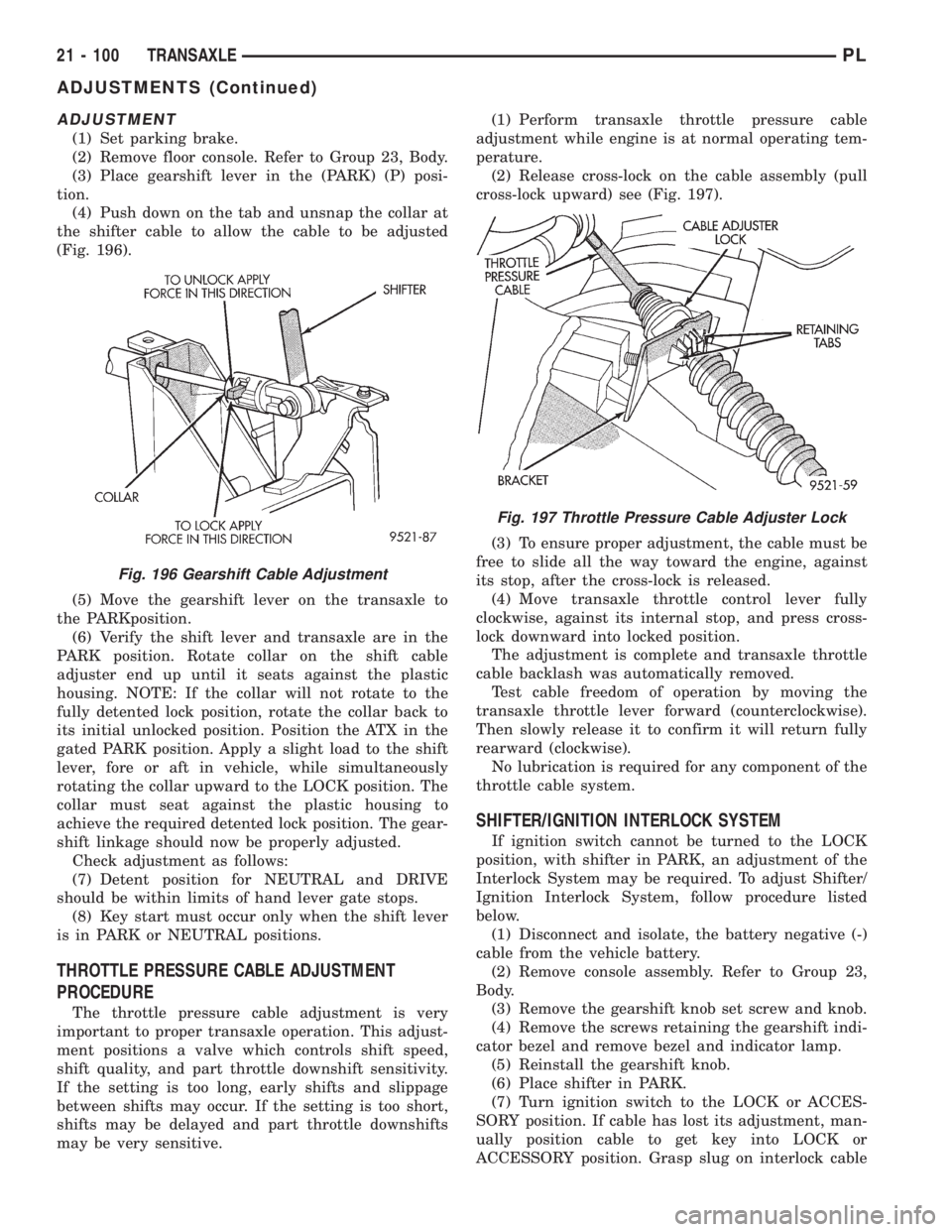
(Fig. 196).
(5) Move the gearshift lever on the transaxle to
the PARKposition.
(6) Verify the shift lever and transaxle are in the
PARK position. Rotate collar on the shift cable
adjuster end up until it seats against the plastic
housing. NOTE: If the collar will not rotate to the
fully detented lock position, rotate the collar back to
its initial unlocked position. Position the ATX in the
gated PARK position. Apply a slight load to the shift
lever, fore or aft in vehicle, while simultaneously
rotating the collar upward to the LOCK position. The
collar must seat against the plastic housing to
achieve the required detented lock position. The gear-
shift linkage should now be properly adjusted.
Check adjustment as follows:
(7) Detent position for NEUTRAL and DRIVE
should be within limits of hand lever gate stops.
(8) Key start must occur only when the shift lever
is in PARK or NEUTRAL positions.
THROTTLE PRESSURE CABLE ADJUSTMENT
PROCEDURE
The throttle pressure cable adjustment is very
important to proper transaxle operation. This adjust-
ment positions a valve which controls shift speed,
shift quality, and part throttle downshift sensitivity.
If the setting is too long, early shifts and slippage
between shifts may occur. If the setting is too short,
shifts may be delayed and part throttle downshifts
may be very sensitive.(1) Perform transaxle throttle pressure cable
adjustment while engine is at normal operating tem-
perature.
(2) Release cross-lock on the cable assembly (pull
cross-lock upward) see (Fig. 197).
(3) To ensure proper adjustment, the cable must be
free to slide all the way toward the engine, against
its stop, after the cross-lock is released.
(4) Move transaxle throttle control lever fully
clockwise, against its internal stop, and press cross-
lock downward into locked position.
The adjustment is complete and transaxle throttle
cable backlash was automatically removed.
Test cable freedom of operation by moving the
transaxle throttle lever forward (counterclockwise).
Then slowly release it to confirm it will return fully
rearward (clockwise).
No lubrication is required for any component of the
throttle cable system.
SHIFTER/IGNITION INTERLOCK SYSTEM
If ignition switch cannot be turned to the LOCK
position, with shifter in PARK, an adjustment of the
Interlock System may be required. To adjust Shifter/
Ignition Interlock System, follow procedure listed
below.
(1) Disconnect and isolate, the battery negative (-)
cable from the vehicle battery.
(2) Remove console assembly. Refer to Group 23,
Body.
(3) Remove the gearshift knob set screw and knob.
(4) Remove the screws retaining the gearshift indi-
cator bezel and remove bezel and indicator lamp.
(5) Reinstall the gearshift knob.
(6) Place shifter in PARK.
(7) Turn ignition switch to the LOCK or ACCES-
SORY position. If cable has lost its adjustment, man-
ually position cable to get key into LOCK or
ACCESSORY position. Grasp slug on interlock cable
Fig. 196 Gearshift Cable Adjustment
Fig. 197 Throttle Pressure Cable Adjuster Lock
21 - 100 TRANSAXLEPL
ADJUSTMENTS (Continued)
Page 1092 of 1200
FLOOR CONSOLE
REMOVAL
(1) Fully apply parking brake.
(2) Remove screw cover plugs over screws just
rearward of cupholders.
(3) Remove screws holding console to floor bracket
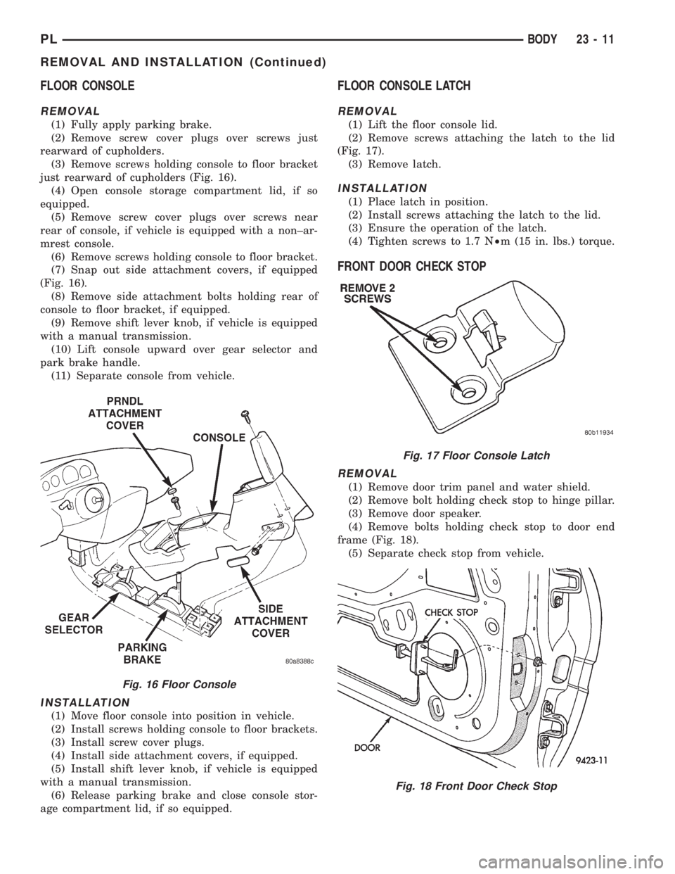
just rearward of cupholders (Fig. 16).
(4) Open console storage compartment lid, if so
equipped.
(5) Remove screw cover plugs over screws near
rear of console, if vehicle is equipped with a non±ar-
mrest console.
(6) Remove screws holding console to floor bracket.
(7) Snap out side attachment covers, if equipped
(Fig. 16).
(8) Remove side attachment bolts holding rear of
console to floor bracket, if equipped.
(9) Remove shift lever knob, if vehicle is equipped
with a manual transmission.
(10) Lift console upward over gear selector and
park brake handle.
(11) Separate console from vehicle.
INSTALLATION
(1) Move floor console into position in vehicle.
(2) Install screws holding console to floor brackets.
(3) Install screw cover plugs.
(4) Install side attachment covers, if equipped.
(5) Install shift lever knob, if vehicle is equipped
with a manual transmission.
(6) Release parking brake and close console stor-
age compartment lid, if so equipped.
FLOOR CONSOLE LATCH
REMOVAL
(1) Lift the floor console lid.
(2) Remove screws attaching the latch to the lid
(Fig. 17).
(3) Remove latch.
INSTALLATION
(1) Place latch in position.
(2) Install screws attaching the latch to the lid.
(3) Ensure the operation of the latch.
(4) Tighten screws to 1.7 N²m (15 in. lbs.) torque.
FRONT DOOR CHECK STOP
REMOVAL
(1) Remove door trim panel and water shield.
(2) Remove bolt holding check stop to hinge pillar.
(3) Remove door speaker.
(4) Remove bolts holding check stop to door end
frame (Fig. 18).
(5) Separate check stop from vehicle.
Fig. 16 Floor Console
Fig. 17 Floor Console Latch
Fig. 18 Front Door Check Stop
PLBODY 23 - 11
REMOVAL AND INSTALLATION (Continued)
Page 1121 of 1200
MOPARTSPRAY WHITE LUBE OR EQUIVALENT
²Door Check Straps
²Liftgate Latches
²Liftgate Prop Pivots
²Ash Receiver
²Fuel Filler Door Remote Control Latch Mecha-
nism
²Parking Brake Mechanism
²Sliding Seat Tracks
²Trunk Latch
MOPARTMULTI±PURPOSE GREASE OR
EQUIVALENT
²All Other Hood Mechanisms
MOPARTLOCK CYLINDER LUBRICANT OR
EQUIVALENT
²Door Lock Cylinders
²Trunk Lock Cylinder
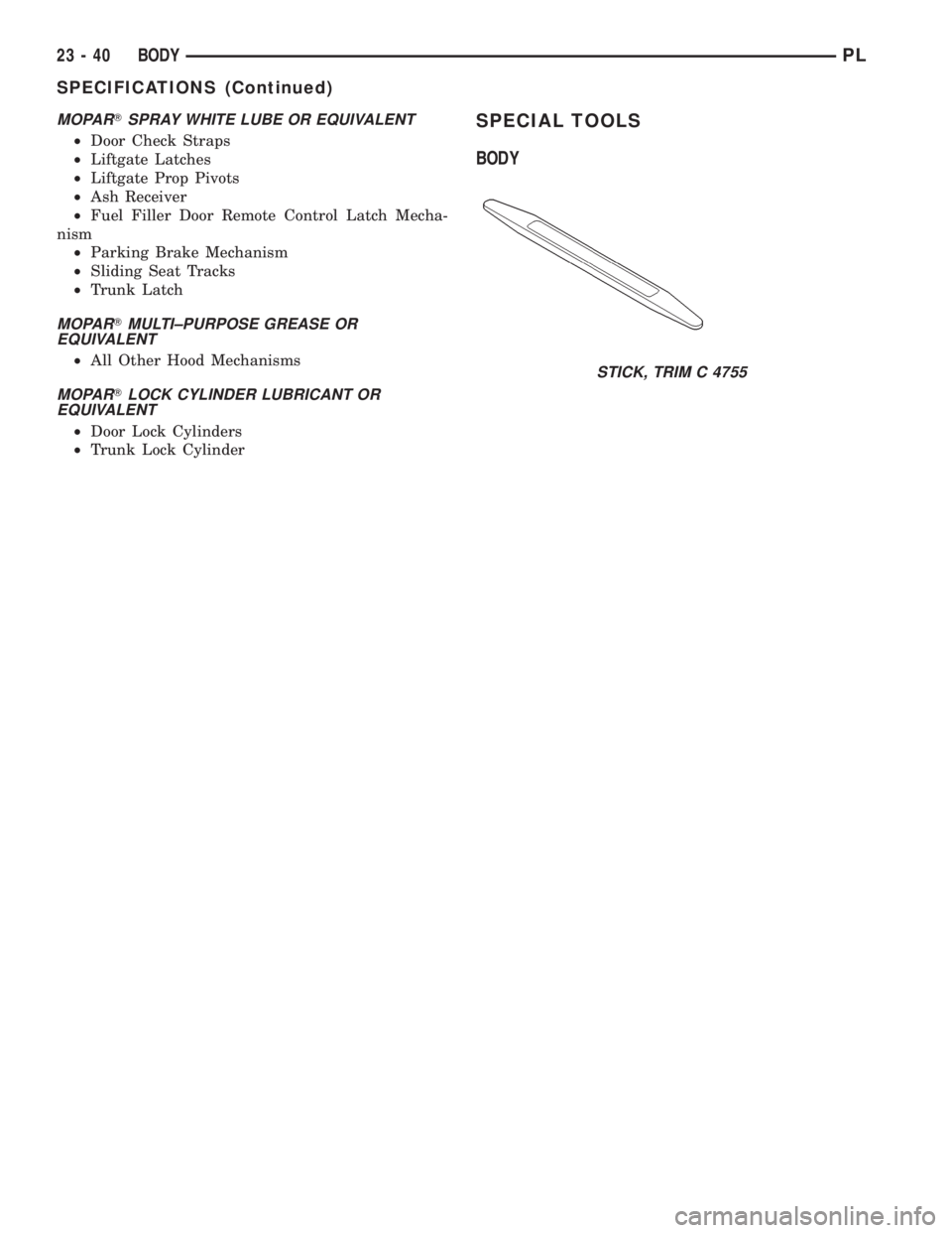
SPECIAL TOOLS
BODY
STICK, TRIM C 4755
23 - 40 BODYPL
SPECIFICATIONS (Continued)
Page 1177 of 1200
The label contains the vehicle's emission specifica-
tions and vacuum hose routings. All hoses must be
connected and routed according to the label.
DIAGNOSIS AND TESTING
LEAK DETECTION PUMP
Refer to the appropriate Powertrain Diagnostic
Procedures Manual for testing procedures.
PCV VALVE TEST
WARNING: APPLY PARKING BRAKE AND/OR
BLOCK WHEELS BEFORE PERFORMING ANY TEST
OR ADJUSTMENT WITH THE ENGINE OPERATING.
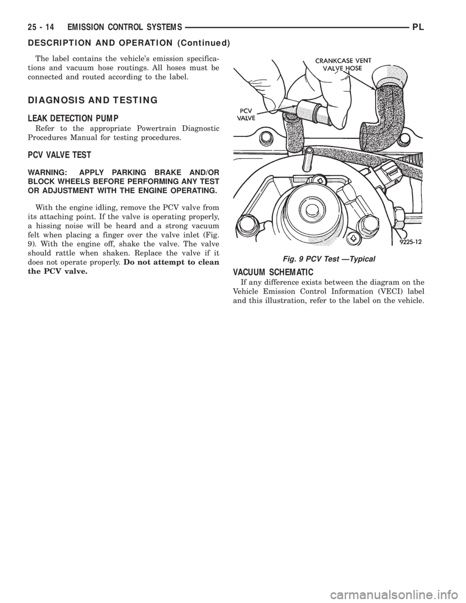
With the engine idling, remove the PCV valve from
its attaching point. If the valve is operating properly,
a hissing noise will be heard and a strong vacuum
felt when placing a finger over the valve inlet (Fig.
9). With the engine off, shake the valve. The valve
should rattle when shaken. Replace the valve if it
does not operate properly.Do not attempt to clean
the PCV valve.
VACUUM SCHEMATIC
If any difference exists between the diagram on the
Vehicle Emission Control Information (VECI) label
and this illustration, refer to the label on the vehicle.
Fig. 9 PCV Test ÐTypical
25 - 14 EMISSION CONTROL SYSTEMSPL
DESCRIPTION AND OPERATION (Continued)