1999 DODGE NEON parking brake
[x] Cancel search: parking brakePage 243 of 1200
performed at each (- ground) connection in this cir-
cuit to locate the excessive resistance.
(7) Testing (+ positive) circuitry:
(a) Touch the positive lead of voltmeter directly
to battery negativePOST.
(b) Touch the negative lead of voltmeter to the
ground terminal stud on the generator case (not
the terminal mounting nut). Voltage should be no
higher than 0.3 volts. If voltage is higher than 0.3
volts, touch test lead to terminal mounting stud
nut and then to the wiring connector. If voltage is
now below 0.3 volts, look for dirty, loose or poor
connection at this point. A voltage drop test may be
performed at each (+ positive) connection in this
circuit to locate the excessive resistance. This test
can also be performed between the generator case
and the engine. If test voltage is higher than 0.3
volts, check for corrosion at generator mounting
points or loose generator mounting.
CURRENT OUTPUT TEST
The current output test will determine if the
charging system can deliver its minimum test cur-
rent (amperage) output. Refer to the Specifications
section at the end of this group for minimum test
current (amperage) requirements.
The first part of this test will determine the com-
bined amperage output of both the generator and the
Electronic Voltage Regulator (EVR) circuitry.
PREPARATION
(1) Determine if any Diagnostic Trouble Codes
(DTC) exist. To determine a DTC, refer to On-Board
Diagnostics in this group. For repair, refer to the
appropriate Powertrain Diagnostic Procedures man-
ual.
(2) Before starting test, make sure battery is in
good condition and is fully-charged. See Group 8A,
Battery for more information.
(3) Check condition of battery cables at battery.
Clean if necessary.
(4) Perform the Voltage Drop Test. This will
ensure clean and tight generator/battery electrical
connections.
(5) Be sure the generator drive belt is properly
tensioned. Refer to Group 7, Cooling System for
information.
(6) A volt/amp tester equipped with both a battery
load control (carbon pile rheostat) and an inductive-
type pickup clamp (ammeter probe) will be used for
this test. Refer to operating instructions supplied
with tester. When using a tester equipped with an
inductive-type clamp, removal of wiring at the gener-
ator will not be necessary.
(7) Start the engine and allow it to reach operating
temperature.
(8) Shut engine off.(9) Turn off all electrical accessories and all vehicle
lighting.
(10) Connect the volt/amp tester leads to the bat-
tery. Be sure the carbon pile rheostat control is in the
OPEN or OFF position before connecting leads. See
Load Test in Group 8A, Battery for more information.
Also refer to the operating instructions supplied with
test equipment.
(11) Connect the inductive clamp (ammeter probe).
Refer to the operating instructions supplied with test
equipment.
(12) If volt/amp tester is not equipped with an
engine tachometer, connect a separate tachometer to
the engine.
TEST
(1) Perform the previous test Preparation.
(2) Fully engage the parking brake.
(3) Start engine.
(4) Bring engine speed to 2500 rpm.
(5) With engine speed held at 2500 rpm, slowly
adjust the rheostat control (load) on the tester to
obtain the highest amperage reading. Do not allow
voltage to drop below 12 volts. Record the reading.
This load test must be performed within 15 sec-
onds to prevent damage to test equipment.On
certain brands of test equipment, this load will be
applied automatically. Refer to the operating manual
supplied with test equipment.
(6) The ammeter reading must meet the Minimum
Test Amps specifications as displayed in the Genera-
tor Ratings chart. This can be found in the Specifica-
tions section at the end of this group. A label stating
a part reference number is attached to the generator
case. On some engines this label may be located on
the bottom of the case. Compare this reference num-
ber to the Generator Ratings chart.
(7) Rotate the load control to the OFF position.
(8) Continue holding engine speed at 2500. If EVR
circuitry is OK, amperage should drop below 15±20
amps. With all electrical accessories and vehicle
lighting off, this could take several minutes of engine
operation. If amperage did not drop, refer to the
appropriate Powertrain Diagnostic Procedures man-
ual for testing.
(9) Remove volt/amp tester.
If minimum amperage could not be met, refer to
the appropriate Powertrain Diagnostic Procedures
manual for testing.
BATTERY TEMPERATURE SENSOR
To perform a complete test of this sensor and its
circuitry, refer to the appropriate Powertrain Diag-
nostic Procedures manual. To test the sensor only,
refer to the following:
(1) The sensor is located under the battery and is
attached to the battery tray (Fig. 5). A two-wire pig-
8C - 8 CHARGING SYSTEMPL
DIAGNOSIS AND TESTING (Continued)
Page 256 of 1200
train Control Module (PCM) with an input signal
(voltage). The signal represents throttle blade posi-
tion. As the position of the throttle blade changes,
the resistance of the TPS changes.
The PCM supplies approximately 5 volts to the
TPS. The TPS output voltage (input signal to the
powertrain control module) represents throttle blade
position. The TPS output voltage to the PCM varies
from approximately 0.38 volts to 1.2 volts at mini-
mum throttle opening (idle) to a maximum of 3.1
volts to 4.4 volts at wide open throttle.
Along with inputs from other sensors, the PCM
uses the TPS input to determine current engine oper-
ating conditions. The PCM also adjusts fuel injector
pulse width and ignition timing based on these
inputs.
IGNITION SWITCH
In the RUN position, the ignition switch connects
power from the Power Distribution Center (PDC) to a
30 amp fuse in the fuse block, back to a bus bar in
the PDC. The bus bar feeds circuits for the Power-
train Control Module (PCM), duty cycle purge sole-
noid, EGR solenoid, and ABS system. The bus bar in
the PDC feeds the coil side of the radiator fan relay,
A/C compressor clutch relay, and the fuel pump relay.
It also feeds the Airbag Control Module (ACM)
LOCK KEY CYLINDER
The lock cylinder is inserted in the end of the
housing opposite the ignition switch. The ignition key
rotates the cylinder to 5 different detents (Fig. 16):
²Accessory
²Off (lock)
²Unlock
²On/Run
²Start
IGNITION INTERLOCK
All vehicles equipped with automatic transaxles
have an interlock system. The system prevents shift-
ing the vehicle out of Park unless the ignition lock
cylinder is in the Off, Run or Start position. In addi-
tion, the operator cannot rotate the key to the lock
position unless the shifter is in the park position. On
vehicles equipped with floor shift refer to Group 21 -
Transaxle for Automatic Transmission Shifter/Igni-
tion Interlock.
DIAGNOSIS AND TESTING
TESTING FOR SPARK AT COILÐ2.0/2.4L
WARNING: THE DIRECT IGNITION SYSTEMS GEN-
ERATES APPROXIMATELY 40,000 VOLTS. PER-
SONAL INJURY COULD RESULT FROM CONTACT
WITH THIS SYSTEM.
The coil pack contains independent coils. Each coil
must be checked individually.
CAUTION: Spark plug wire damage may occur if
the spark plug is moved more than 1/4 inch away
from the engine ground.
CAUTION: Do not leave any one spark plug cable
disconnected any longer than 30 seconds or possi-
ble heat damage to catalytic converter will occur.
CAUTION: Test must be performed at idle and in
park only with the parking brake on.
NOTE: New isolated engine valve cover may not
provide adequate ground. Use engine block as
engine ground.
Fig. 15 MAP/IAT sensorÐDOHCFig. 16 Ignition Lock Cylinder Detents
PLIGNITION SYSTEM 8D - 7
DESCRIPTION AND OPERATION (Continued)
Page 271 of 1200
When the ignition switch is in the OFF position, or
when the radio frequency is being displayed, time
keeping is accurately maintained.
The procedure for setting the clock varies slightly
with each radio. The correct procedure is described in
the individual radio operating instructions. Refer to
the Owner's Manual supplied with the vehicle.
INSTRUMENT CLUSTER
There are two conventional instrument cluster
assemblies available. The clusters electronically drive
the speedometer, odometer, and gauges (Fig. 1) and
(Fig. 2).
GAUGES
All gauges in the electronic clusters are the analog
type gauges. When the ignition switch is moved to
the OFF position, the cluster drives each gauge to its
lowest position.
WARNING AND INDICATOR LAMPS
The instrument cluster has warning lamps and
indicators for the following systems:
²Airbag
²Anti-lock Brakes (ABS) if equipped
²Brake warning
²Charging System
²Door Ajar
²High beam indicator
²Low oil pressure
²Malfunction indicator (service engine soon) lamp
²Right and left turn signals.
²Seat belt warning
DIAGNOSIS AND TESTING
AIRBAG WARNING SYSTEM
For testing of this system refer to Group 8M,
Restraint Systems.
BRAKE SYSTEM WARNING LAMP TEST
The brake warning lamp illuminates when the
parking brake is applied with ignition switch turned
to the ON position. The same lamp will also illumi-
nate if one of the two service brake systems fail the
when brake pedal is applied.
To test the system:
²As the ignition switch is turned to the start posi-
tion the lamp should light.
²Turn ignition switch to the ON position and
apply the parking brake. The lamp should light.
If lamp fails to light inspect for:
²A burned out lamp
²Loose, corroded or damaged socket
²A damaged circuit board
²A broken or disconnected wire at the switch
²Defective switch
To test the service brake warning system, refer to
Group 5, Brakes, Hydraulic System Control Valves.
FOG LAMP SWITCH TEST
(1) Remove the fog lamp switch. Refer to the Rear
Window Defogger and/or Fog Lamp Switch Removal.
(2) Using two jumper wires, connect Pin 2 and Pin
4 of the switch to battery voltage.
(3) Using a test lamp, connect the test lamp to Pin
3 as shown in (Fig. 3). Refer to (Fig. 4) for fog lamp
switch circuit.
(4) Push the fog lamp switch button. The test lamp
and the LED indicator on the front of the switch
should illuminate.
(5) If either the LED or the test lamp fails to illu-
minate, replace the switch.Fig. 1 Instrument Cluster Without Tachometer
Fig. 2 Instrument Cluster With Tachometer
Fig. 3 Fog Lamp Switch Test
8E - 2 INSTRUMENT PANEL AND SYSTEMSPL
DESCRIPTION AND OPERATION (Continued)
Page 277 of 1200
(3) Disconnect the odometer connector and remove
eight attaching screws that attach the printed circuit
board and housing (Fig. 15).
(4) Carefully remove printed circuit board from the
cluster.
INSTALLATION
For installation, reverse the above procedures.
Carefully place board on the cluster and ensure that
the odometer connector is placed through the board.
Gently press board on cluster with a slight rocking
motion to ensure pins on gauges line up.
DOME LENS/LAMP
REMOVAL
Pry either the forward or rearward edge of the lens
away from the retainer and replace the lamp.
INSTALLATION
For installation, snap lens into retainer.
FLOOR CONSOLE
REMOVAL
(1) Remove the MTX shifter knob only.
(2) Remove the attaching screws from each side of
the cup holder.
(a) Non-armrest console. Remove the two screws
from the rear of the console (Fig. 16).
(b) Armrest console. Remove the four screws in
the console bin.
(3) Pull the parking brake lever up all the way.
(4) Lift the console at the rear and guide it out
from under the instrument panel.
INSTALLATION
For installation, reverse the above procedures.
GAUGE
REMOVAL
(1) Remove the cluster. Refer to Cluster Removal.
(2) Remove the attaching screws PC board cover
(Fig. 15). The bottom screws attaching lens to hous-
ing can be accessed without removing the foam pad.
(3) Disconnect the odometer connector.
(4) Remove the lens attaching screws and remove
the lens.
(5) Carefully pry out the dial and gauge assembly.
INSTALLATION
For installation, reverse the above procedures.
(1) When handling or storing the cluster ensure
that overlays are not damaged. Set the cluster in the
face up position or the gauge operation will be dam-
aged.
(2) The gauges are replaced as an dial and gauge
assembly.
GLOVE BOX DOOR/BIN
REMOVAL
(1) Disconnect battery negative cable and isolate it
or remove fuse 12 prior to removing the switch, or
the wires may short to ground.
(2) Remove the screws along the bottom of glove
box door.
(3) Open the glove box and push the glove box
sides inward allowing the door bumpers to clear and
box to tip forward.
(4) Pull the glove box door/bin rearward and
remove from vehicle.
INSTALLATION
For installation, reverse the above procedures.
Fig. 15 Printed Circuit Board
Fig. 16 Floor Console with Transmission Range
Indicator
8E - 8 INSTRUMENT PANEL AND SYSTEMSPL
REMOVAL AND INSTALLATION (Continued)
Page 283 of 1200
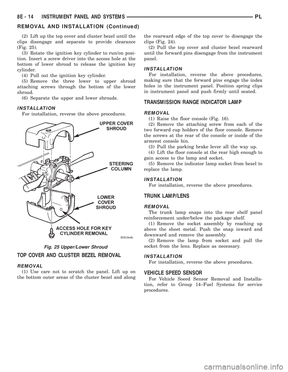
(2) Lift up the top cover and cluster bezel until the
clips disengage and separate to provide clearance
(Fig. 25).
(3) Rotate the ignition key cylinder to run/on posi-
tion. Insert a screw driver into the access hole at the
bottom of lower shroud to release the ignition key
cylinder.
(4) Pull out the ignition key cylinder.
(5) Remove the three lower to upper shroud
attaching screws through the bottom of the lower
shroud.
(6) Separate the upper and lower shrouds.
INSTALLATION
For installation, reverse the above procedures.
TOP COVER AND CLUSTER BEZEL REMOVAL
REMOVAL
(1) Use care not to scratch the panel. Lift up on
the bottom outer areas of the cluster bezel and alongthe rearward edge of the top cover to disengage the
clips (Fig. 24).
(2) Pull the top cover and cluster bezel rearward
until the forward pins disengage from the instrument
panel.
INSTALLATION
For installation, reverse the above procedures,
making sure that the forward pins engage the index
holes in the instrument panel. Position spring clips
in instrument panel and push firmly until seated.
TRANSMISSION RANGE INDICATOR LAMP
REMOVAL
(1) Raise the floor console (Fig. 16).
(2) Remove the attaching screw from each of the
two forward cup holders of the floor console. Remove
the screws at the rear of the console or inside of the
armrest console bin.
(3) Pull the parking brake lever all the way up.
(4) Lift the floor console at the rear high enough to
gain access to the lamp and socket.
(5) Remove the indicator lamp socket from bezel to
replace the lamp.
INSTALLATION
For installation, reverse the above procedures.
TRUNK LAMP/LENS
REMOVAL
The trunk lamp snaps into the rear shelf panel
reinforcement under/below the package shelf.
(1) Remove the socket assembly by reaching up
above the sheet metal. Push the snap inward and
downward and remove the assembly.
(2) Remove the lamp from socket and pull the
socket from the lens. Replace as necessary.
INSTALLATION
For installation, reverse the above procedures.
VEHICLE SPEED SENSOR
For Vehicle Soeed Sensor Removal and Installa-
tion, refer to Group 14±Fuel Systems for service
procedures.
Fig. 25 Upper/Lower Shroud
8E - 14 INSTRUMENT PANEL AND SYSTEMSPL
REMOVAL AND INSTALLATION (Continued)
Page 355 of 1200
tal deployment occurs. Do not place undeployed air-
bag face down on a solid surface, the airbag will
propel into the air if accidental deployment occurs.
MAINTENANCE INSPECTION
(1) Check the airbag warning lamp for proper
operation as follows:
(a) Turn ignition switch to the ON position, the
airbag warning lamp should light. If not, test the
system using a scan tool and Passive Restraint
System Diagnostic Procedures Manual. Repair as
required.
(b) The airbag warning lamp lights, but fails to
go out after eight seconds. Test the system using a
scan tool and Passive Restraint System Diagnostic
Procedures Manual. Repair as required.
(c) After correcting active malfunction erase
stored diagnostic codes.
REMOVAL AND INSTALLATION
AIRBAG CONTROL MODULE (ACM)
REMOVAL
WARNING: THE ACM CONTAINS A SAFING SEN-
SOR WHICH ENABLES THE SYSTEM TO DEPLOY
THE AIRBAGS. TO AVOID ACCIDENTAL DEPLOY-
MENT, NEVER CONNECT THE ACM ELECTRICALLY
TO THE SYSTEM WHILE VEHICLE BATTERY IS
CONNECTED.
DISCONNECT AND ISOLATE THE BATTERY NEG-
ATIVE (GROUND) CABLE BEFORE BEGINNING ANY
AIRBAG SYSTEM COMPONENT REMOVAL OR
INSTALLATION PROCEDURE. THIS WILL DISABLE
THE AIRBAG SYSTEM. FAILURE TO DISCONNECT
BATTERY COULD RESULT IN ACCIDENTAL AIRBAG
DEPLOYMENT AND POSSIBLE PERSONAL INJURY.
ALLOW SYSTEM CAPACITOR TO DISCHARGE
FOR 2 MINUTES BEFORE REMOVING ANY AIRBAG
COMPONENTS.
CAUTION: Failure to follow the parking brake ser-
vice procedures can result in damage to the park-
ing brake mechanism.
(1) Disconnect and isolate the battery negative
cable.
(2) Manual transaxle only, remove shifter knob
fastener and remove shifter knob.
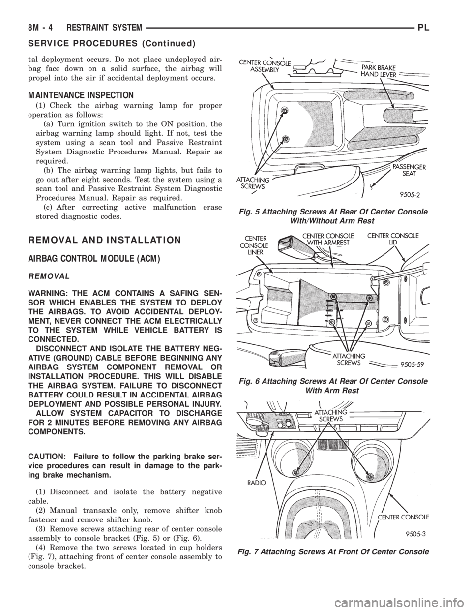
(3) Remove screws attaching rear of center console
assembly to console bracket (Fig. 5) or (Fig. 6).
(4) Remove the two screws located in cup holders
(Fig. 7), attaching front of center console assembly to
console bracket.
Fig. 5 Attaching Screws At Rear Of Center Console
With/Without Arm Rest
Fig. 6 Attaching Screws At Rear Of Center Console
With Arm Rest
Fig. 7 Attaching Screws At Front Of Center Console
8M - 4 RESTRAINT SYSTEMPL
SERVICE PROCEDURES (Continued)
Page 356 of 1200
(5) Raise park brake hand lever assembly as high
as it will go for required clearance to remove center
console.
(6) Remove center console assembly from vehicle.
WARNING: THE AUTO ADJUSTING FEATURE OF
THIS PARKING BRAKE LEVER ASSEMBLY CON-
TAINS A CLOCK SPRING LOADED TO APPROXI-
MATELY 20 POUNDS. DO NOT RELEASE THE AUTO
ADJUSTER LOCKOUT DEVICE BEFORE INSTALL-
ING CABLES INTO THE EQUALIZER. KEEP HANDS
OUT OF AUTO ADJUSTER SECTOR AND PAWL
AREA. FAILURE TO OBSERVE CAUTION IN HAN-
DLING THIS MECHANISM COULD LEAD TO SERI-
OUS INJURY.
WHEN REPAIRS TO THE PARK BRAKE HAND
LEVER ASSEMBLY OR CABLES IS REQUIRED, THE
AUTO ADJUSTER MUST BE RELOADED AND
LOCKED OUT.
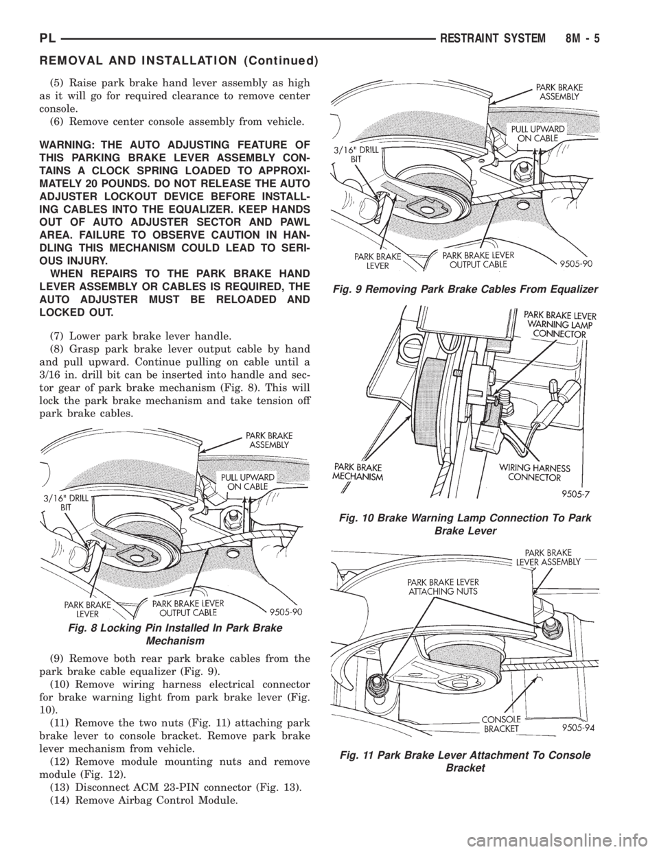
(7) Lower park brake lever handle.
(8) Grasp park brake lever output cable by hand
and pull upward. Continue pulling on cable until a
3/16 in. drill bit can be inserted into handle and sec-
tor gear of park brake mechanism (Fig. 8). This will
lock the park brake mechanism and take tension off
park brake cables.
(9) Remove both rear park brake cables from the
park brake cable equalizer (Fig. 9).
(10) Remove wiring harness electrical connector
for brake warning light from park brake lever (Fig.
10).
(11) Remove the two nuts (Fig. 11) attaching park
brake lever to console bracket. Remove park brake
lever mechanism from vehicle.
(12) Remove module mounting nuts and remove
module (Fig. 12).
(13) Disconnect ACM 23-PIN connector (Fig. 13).
(14) Remove Airbag Control Module.
Fig. 8 Locking Pin Installed In Park Brake
Mechanism
Fig. 9 Removing Park Brake Cables From Equalizer
Fig. 10 Brake Warning Lamp Connection To Park
Brake Lever
Fig. 11 Park Brake Lever Attachment To Console
Bracket
PLRESTRAINT SYSTEM 8M - 5
REMOVAL AND INSTALLATION (Continued)
Page 401 of 1200

WARNING: BE SURE THAT THE IGNITION SWITCH
ALWAYS IS IN THE OFF POSITION, UNLESS THE
PROCEDURE REQUIRES IT TO BE ON.
WARNING: SET THE PARKING BRAKE WHEN
WORKING ON ANY VEHICLE. AN AUTOMATIC
TRANSMISSION SHOULD BE IN PARK. A MANUAL
TRANSMISSION SHOULD BE IN NEUTRAL.
WARNING: OPERATE THE ENGINE ONLY IN A
WELL-VENTILATED AREA.
WARNING: KEEP AWAY FROM MOVING PARTS
WHEN THE ENGINE IS RUNNING, ESPECIALLY THE
FAN AND BELTS.
WARNING: TO PREVENT SERIOUS BURNS, AVOID
CONTACT WITH HOT PARTS SUCH AS THE RADIA-
TOR, EXHAUST MANIFOLD(S), TAIL PIPE, CATA-
LYTIC CONVERTER, AND MUFFLER.
WARNING: DO NOT ALLOW FLAME OR SPARKS
NEAR THE BATTERY. GASES ARE ALWAYS
PRESENT IN AND AROUND THE BATTERY.
WARNING: ALWAYS REMOVE RINGS, WATCHES,
LOOSE HANGING JEWELRY, AND LOOSE CLOTH-
ING.
TAKE OUTS
The abbreviation T/O is used in the component
location section to indicate a point in which the wir-
ing harness branches out to a component.
ELECTROSTATIC DISCHARGE (ESD) SENSITIVE
DEVICES
All ESD sensitive components are solid state and a
symbol (Fig. 4) is used to indicate this. When han-
dling any component with this symbol comply with
the following procedures to reduce the possibility of
electrostatic charge build up on the body and inad-
vertent discharge into the component. If it is not
known whether the part is ESD sensitive, assume
that it is.
(1) Always touch a known good ground before han-
dling the part. This should be repeated while han-
dling the part and more frequently after sliding
across a seat, sitting down from a standing position,
or walking a distance.
(2) Avoid touching electrical terminals of the part,
unless instructed to do so by a written procedure.(3) When using a voltmeter, be sure to connect the
ground lead first.
(4) Do not remove the part from its protective
packing until it is time to install the part.
(5) Before removing the part from its package,
ground the package to a known good ground on the
vehicle.
DIAGNOSIS AND TESTING
TROUBLESHOOTING TOOLS
When diagnosing a problem in an electrical circuit
there are several common tools necessary. These tools
are listed and explained below.
²Jumper Wire - This is a test wire used to con-
nect two points of a circuit. It can be used to bypass
an open in a circuit.
WARNING: NEVER USE A JUMPER WIRE ACROSS
A LOAD, SUCH AS A MOTOR, CONNECTED
BETWEEN A BATTERY FEED AND GROUND.
²Voltmeter - Used to check for voltage on a cir-
cuit. Always connect the black lead to a known good
ground and the red lead to the positive side of the
circuit.
CAUTION: Most of the electrical components used
in today's vehicle are solid state. When checking
voltages in these circuits use a meter with a 10-me-
gohm or greater impedance rating.
²Ohmmeter - Used to check the resistance
between two points of a circuit. Low or no resistance
in a circuit means good continuity.
CAUTION: - Most of the electrical components used
in today's vehicle are Solid State. When checking
resistance in these circuits use a meter with a 10-
megohm or greater impedance rating. In addition,
make sure the power is disconnected from the cir-
cuit. Circuits that are powered up by the vehicle
electrical system can cause damage to the equip-
ment and provide false readings.
Fig. 4 Electrostatic Discharge Symbol
8W - 01 - 8 8W - 01 GENERAL INFORMATIONPL
DESCRIPTION AND OPERATION (Continued)