1999 DODGE NEON parking brake
[x] Cancel search: parking brakePage 134 of 1200
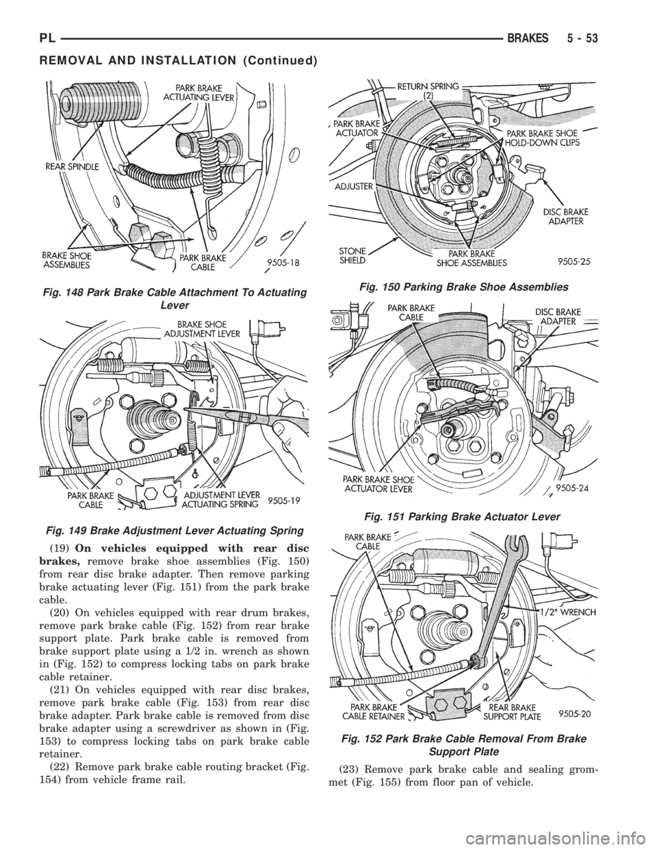
(19)On vehicles equipped with rear disc
brakes,remove brake shoe assemblies (Fig. 150)
from rear disc brake adapter. Then remove parking
brake actuating lever (Fig. 151) from the park brake
cable.
(20) On vehicles equipped with rear drum brakes,
remove park brake cable (Fig. 152) from rear brake
support plate. Park brake cable is removed from
brake support plate using a 1/2 in. wrench as shown
in (Fig. 152) to compress locking tabs on park brake
cable retainer.
(21) On vehicles equipped with rear disc brakes,
remove park brake cable (Fig. 153) from rear disc
brake adapter. Park brake cable is removed from disc
brake adapter using a screwdriver as shown in (Fig.
153) to compress locking tabs on park brake cable
retainer.
(22) Remove park brake cable routing bracket (Fig.
154) from vehicle frame rail.(23) Remove park brake cable and sealing grom-
met (Fig. 155) from floor pan of vehicle.
Fig. 148 Park Brake Cable Attachment To Actuating
Lever
Fig. 149 Brake Adjustment Lever Actuating Spring
Fig. 150 Parking Brake Shoe Assemblies
Fig. 151 Parking Brake Actuator Lever
Fig. 152 Park Brake Cable Removal From Brake
Support Plate
PLBRAKES 5 - 53
REMOVAL AND INSTALLATION (Continued)
Page 136 of 1200
to one-half specified torque. Then repeat pattern,
fully tightening stud nuts to 135 N´m (100 ft. lbs.).
(11) Lower vehicle.
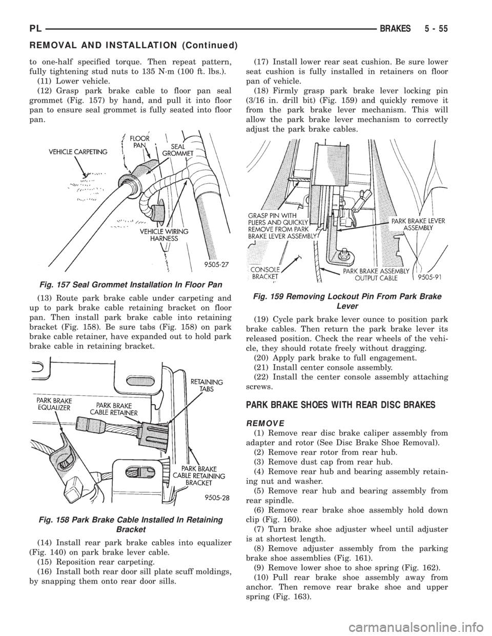
(12) Grasp park brake cable to floor pan seal
grommet (Fig. 157) by hand, and pull it into floor
pan to ensure seal grommet is fully seated into floor
pan.
(13) Route park brake cable under carpeting and
up to park brake cable retaining bracket on floor
pan. Then install park brake cable into retaining
bracket (Fig. 158). Be sure tabs (Fig. 158) on park
brake cable retainer, have expanded out to hold park
brake cable in retaining bracket.
(14) Install rear park brake cables into equalizer
(Fig. 140) on park brake lever cable.
(15) Reposition rear carpeting.
(16) Install both rear door sill plate scuff moldings,
by snapping them onto rear door sills.(17) Install lower rear seat cushion. Be sure lower
seat cushion is fully installed in retainers on floor
pan of vehicle.
(18) Firmly grasp park brake lever locking pin
(3/16 in. drill bit) (Fig. 159) and quickly remove it
from the park brake lever mechanism. This will
allow the park brake lever mechanism to correctly
adjust the park brake cables.
(19) Cycle park brake lever ounce to position park
brake cables. Then return the park brake lever its
released position. Check the rear wheels of the vehi-
cle, they should rotate freely without dragging.
(20) Apply park brake to full engagement.
(21) Install center console assembly.
(22) Install the center console assembly attaching
screws.
PARK BRAKE SHOES WITH REAR DISC BRAKES
REMOVE
(1) Remove rear disc brake caliper assembly from
adapter and rotor (See Disc Brake Shoe Removal).
(2) Remove rear rotor from rear hub.
(3) Remove dust cap from rear hub.
(4) Remove rear hub and bearing assembly retain-
ing nut and washer.
(5) Remove rear hub and bearing assembly from
rear spindle.
(6) Remove rear brake shoe assembly hold down
clip (Fig. 160).
(7) Turn brake shoe adjuster wheel until adjuster
is at shortest length.
(8) Remove adjuster assembly from the parking
brake shoe assemblies (Fig. 161).
(9) Remove lower shoe to shoe spring (Fig. 162).
(10) Pull rear brake shoe assembly away from
anchor. Then remove rear brake shoe and upper
spring (Fig. 163).
Fig. 157 Seal Grommet Installation In Floor Pan
Fig. 158 Park Brake Cable Installed In Retaining
Bracket
Fig. 159 Removing Lockout Pin From Park Brake
Lever
PLBRAKES 5 - 55
REMOVAL AND INSTALLATION (Continued)
Page 147 of 1200
(3)Be sure parking brake lever is fully
released.
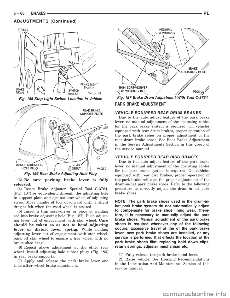
(4) Insert Brake Adjuster, Special Tool C-3784,
(Fig. 187) or equivalent, through the adjusting hole
in support plate and against star wheel of adjusting
screw. Move handle of tool downward until a slight
drag is felt when the road wheel is rotated.
(5) Insert a thin screwdriver or piece of welding
rod into brake adjusting hole (Fig. 187). Push adjust-
ing lever out of engagement with star wheel.Care
should be taken so as not to bend adjusting
lever or distort lever spring.While holding
adjusting lever out of engagement with star wheel,
back off star wheel to ensure a free wheel with no
brake shoe drag.
(6) Repeat above adjustment at the other rear
wheel. Install adjusting hole rubber plugs (Fig. 186)
in rear brake supports.
(7) Apply and release the park brake lever one
timeafterwheel brake adjustment.
PARK BRAKE ADJUSTMENT
VEHICLE EQUIPPED REAR DRUM BRAKES
Due to the auto adjust feature of the park brake
lever, no manual adjustment of the operating cables
for the park brake system is required. On vehicles
equipped with rear drum brakes, proper operation of
the park brake relies on proper adjustment of the
rear drum brake shoes. See Rear Brake Adjustment
in the Service Adjustments Section in this group of
the service manual.
VEHICLE EQUIPPED REAR DISC BRAKES
Due to the auto adjust feature of the park brake
lever, no manual adjustment of the operating cables
for the park brake system is required. On vehicles
equipped with rear disc brakes, proper operation of
the park brake relies on the proper adjustment of the
drum-in-hat park brake shoes. Refer to the following
procedure to correctly adjust the drum-in-hat park
brake shoes.
NOTE: The park brake shoes used in the drum-in-
hat park brake system do not automatically adjust
to compensate for brake shoe lining wear. There-
fore, it is necessary to manually adjust the park
brake shoes. Manual adjustment of the park brake
shoes is required whenever any of the following
occurs. Excessive travel of the of the park brake
lever, new park brake shoes are installed, or any
service is performed that effects the location of the
park brake shoes like: replacing hold down clips,
return springs, adjuster mechanism etc.
(1) Fully release the park brake hand lever.
(2) Raise vehicle. See Hoisting Recommendations
in the Lubrication And Maintenance Section of this
service manual.
Fig. 185 Stop Light Switch Location In Vehicle
Fig. 186 Rear Brake Adjusting Hole Plug
Fig. 187 Brake Drum Adjustment With Tool C-3784
5 - 66 BRAKESPL
ADJUSTMENTS (Continued)
Page 149 of 1200
DESCRIPTION TORQUE
MASTER CYLINDER:
To Vacuum Booster Mounting Nut.28 N´m (250 in. lbs.)
BRAKE BOOSTER:
To Dash Panel Mounting Nuts . .28 N´m (250 in. lbs.)
REAR WHEEL CYLINDER:
To Support Plate Mounting Bolts.13 N´m (115 in. lbs.)
Bleeder Screw...............10N´m(80in.lbs.)
BRAKE SUPPORT PLATE:
To Axle Mounting Bolts.........75N´m(55ft.lbs.)
REAR DISC BRAKE ADAPTER:
To Axle Mounting Bolts.........75N´m(55ft.lbs.)
DISC BRAKE CALIPER:
Guide Pin Bolts.............22N´m(192 in. lbs.)
Bleeder Screw..............15N´m(125 in. lbs.)
ABS HYDRAULIC CONTROL UNIT:
To Mounting Bracket Bolts.....28N´m(250 in. lbs.)
Bracket To Frame Rail Mounting Bolt (Top) . .18 N´m
(160 in. lbs.)
Bracket To Frame Rail Mounting Bolts (Side).22 N´m
(200 in. lbs.)
PARKING BRAKE:
Lever Mounting Nuts.........28N´m(250 in. lbs.)
REAR HUB AND BEARING:
To Knuckle Retaining Nut.....217 N´m (160 ft. lbs.)
WHEEL:
Stud Lug Nut........109±150 N´m (80±110 ft. lbs.)
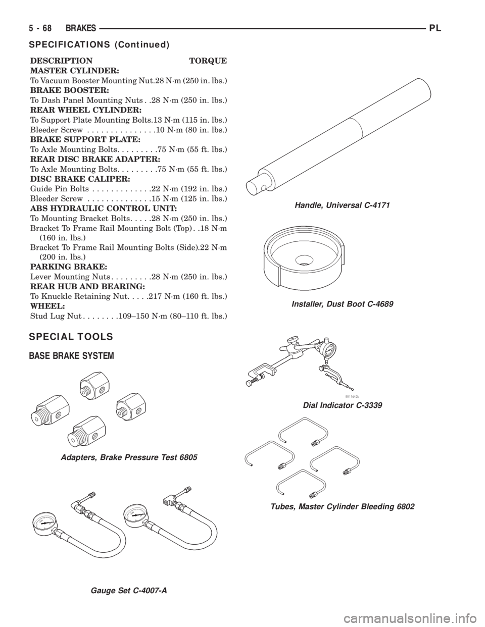
SPECIAL TOOLS
BASE BRAKE SYSTEM
Adapters, Brake Pressure Test 6805
Gauge Set C-4007-A
Handle, Universal C-4171
Installer, Dust Boot C-4689
Dial Indicator C-3339
Tubes, Master Cylinder Bleeding 6802
5 - 68 BRAKESPL
SPECIFICATIONS (Continued)
Page 156 of 1200
cally cleared from the CAB memory after the identi-
cal fault has not been seen during the next 255 key
cycles of vehicle operation.
CONTROLLER ANTILOCK BRAKE INPUTS
²Four wheel speed sensors.
²Stop lamp switch.
²Ignition switch.
²System relay voltage.
²Ground.
²Diagnostics Communications (CCD)
CONTROLLER ANTILOCK BRAKE OUTPUTS
²ABS warning lamp actuation.
²Diagnostic communication. (CCD)
ABS WARNING LAMP (YELLOW)
The ABS system uses a yellow colored ABS Warn-
ing Lamp. The ABS warning lamp is located on the
lower left side of the instrument pane. The purpose
of the warning lamp is discussed in detail below.
The ABS warning lamp will turn on when the CAB
detects a condition which results in a shutdown of
ABS function. When the ignition key is turned to the
on position, the ABS Warning Lamp is on until the
CAB completes its self tests and turns the lamp off
(approximately 4 seconds after the ignition switch is
turned on). Under most conditions, when the ABS
warning lamp is on, only the ABS function of the
brake system is affected. The standard brake system
and the ability to stop the car will not be affected
when only the ABS warning lamp is on.
The ABS warning lamp is controlled by the CAB.
The CAB turns on the yellow ABS warning lamp by
grounding the circuit.
HYDRAULIC CIRCUITS AND VALVE OPERATION
Through the following operation descriptions the
function of the various hydraulic control valves in the
ABS will be described. The fluid control valves men-
tioned below, control the flow of pressurized brake
fluid to the wheel brakes during the different modes
of ABS braking.
For explanation purposes, all wheel speed sensors
except the right front are sending the same wheel
speed information. The following diagrams show only
the right front wheel in a antilock braking condition.
NORMAL BRAKING HYDRAULIC CIRCUIT AND
SOLENOID VALVE FUNCTION
This condition is the normal operation of the vehi-
cles base brake hydraulic system. The hydraulic sys-
tem circuit diagram (Fig. 11) shows a situation where
no wheel spin or slip is occurring relative to the
speed of the vehicle. The driver is applying the brake
pedal to build pressure in the brake hydraulic system
to apply the brakes and stop the vehicle.
TEVES MARK 20 ABS CIRCUIT AND
SOLENOID VALVE FUNCTION
This hydraulic circuit diagram (Fig. 12) shows the
vehicle in the ABS braking mode. This hydraulic cir-
cuit (Fig. 12) shows a situation where one wheel is
slipping because the driver is attempting to stop the
vehicle at a faster rate than the surface the vehicle's
tires are on will allow. The normally open and nor-
mally closed valves modulate the brake hydraulic
pressure as required. The pump/motor is switched on
so that the brake fluid from the low pressure accu-
mulators is returned to the master cylinder circuits.
The brake fluid will then be routed to either the mas-
ter cylinder or the wheel brake depending on the
position of the normally open valve.
TEVES MARK 20 SECONDARY ABS CIRCUIT
AND SOLENOID VALVE FUNCTION
This hydraulic circuit diagram (Fig. 13) shows the
vehicle in the ABS braking mode. This hydraulic cir-
cuit (Fig. 13) shows a situation where one wheel is
slipping because the driver is attempting to stop the
vehicle at a faster rate than the surface the vehicle's
tires are on will allow. The normally open and nor-
mally closed valves modulate the brake hydraulic
pressure as required. The pump/motor is switched on
so that the brake fluid from the low pressure accu-
mulators is returned to the master cylinder circuits.
The brake fluid will then be routed to either the mas-
ter cylinder or the wheel brake depending on the
position of the normally open valve. A volume of 1.2
cc's of brake fluid is taken in by the lip seal saver
(Fig. 13) to protect the lip seals on the piston of the
master cylinder.
DIAGNOSIS AND TESTING
ABS GENERAL DIAGNOSTICS INFORMATION
This section contains the information necessary to
diagnose the ITT Teves Mark 20 ABS Brake System.
Specifically, this section should be used to help diag-
nose conditions which result in any of the following:
(1) ABS Warning Lamp turned on.
(2) Brakes Lock-up on hard application
Diagnosis of base brake conditions which are obvi-
ously mechanical in nature should be directed to
Group 5 Brakes in this service manual. This includes
brake noise, brake pulsation, lack of power assist,
parking brake, Red BRAKE Warning Lamp lighting,
or vehicle vibration during normal braking.
Many conditions that generate customer com-
plaints may be normal operating conditions, but are
judged to be a problem due to not being familiar with
the ABS system. These conditions can be recognized
without performing extensive diagnostic work, given
adequate understanding of the operating principles
PLBRAKES 5 - 75
DESCRIPTION AND OPERATION (Continued)
Page 170 of 1200
bolt attaching speed sensor cable routing bracket to
rear strut assembly (Fig. 40).
(6) Remove speed sensor head from the disc brake
adapter. If the speed sensor head has seized in the
adapter, DO NOT USE PLIERS ON SENSOR HEAD.
INSTALL
(1) Install wheel speed sensor head into disc brake
adapter (Fig. 40).
(2) Install wheel speed sensor attaching bolt (Fig.
40). Tighten the attaching bolt to a torque of 7 N´m
(60 in. lbs.)
(3) Install the brake flex hose and wheel speed
sensor cable routing bracket on the rear strut
bracket (Fig. 40).
(4) Install wheel speed sensor cable into the rout-
ing clips on the rear brake flex hose and chassis
brake tube.
(5) Plug speed sensor cable connector into vehicle
wiring harness (Fig. 39). Install clip (Fig. 39) attach-
ing speed sensor cable connector to vehicle body.
(6) Install the tire and wheel assembly on vehicle.
(7) Road test vehicle to ensure proper operation of
the base and ABS systems.
SPECIFICATIONS
SPEED SENSOR TONE WHEEL RUNOUT
The total indicator runout allowed for both the
front and rear tone wheel measured using a dial indi-
cator is 0.25 mm (.009 in.).
WHEEL SPEED SENSOR TO TONE WHEEL
CLEARANCE
FRONT WHEEL
Minimum Clearance 0.17 mm (0.007 in.)
Maxamum Clearance 1.80 mm (0.072 in.)
REAR WHEEL
Minimum Clearance 0.37 mm (0.015 in.)
Maxamum Clearance 1.50 mm (0.059 in.)
BRAKE FASTENER TORQUE SPECIFICATIONS
DESCRIPTION TORQUE
BRAKE TUBES:
Tube Nuts To Fittings And
Components Except HCU. . . . 17 N´m (145 in. lbs.)
From Master Cylinder To HCU
At HCU Ports.............21N´m(185 in. lbs.)
BRAKE HOSE:
To Caliper Banjo Bolt..........48N´m(35ft.lbs.)
Intermediate Bracket.........12N´m(105 in. lbs.)
MASTER CYLINDER:
To Vacuum Booster
Mounting Nut............28N´m(250 in. lbs.)
BRAKE BOOSTER:
To Dash Panel Mounting Nuts . .28 N´m (250 in. lbs.)
REAR WHEEL CYLINDER:
To Support Plate
Mounting Bolts............13N´m(115in.lbs.)
Bleeder Screw...............10N´m(80in.lbs.)
BRAKE SUPPORT PLATE:
To Axle Mounting Bolts.........75N´m(55ft.lbs.)
REAR DISC BRAKE ADAPTER:
To Axle Mounting Bolts.........75N´m(55ft.lbs.)
DISC BRAKE CALIPER:
Guide Pin Bolts.............22N´m(192 in. lbs.)
Bleeder Screw..............15N´m(125 in. lbs.)
ABS HYDRAULIC CONTROL UNIT:
To Mounting Bracket Bolts.....28N´m(250 in. lbs.)
Bracket To Frame Rail
Mounting Bolt (Top)........18N´m(160 in. lbs.)
Bracket To Frame Rail
Mounting Bolts (Side)......22N´m(200 in. lbs.)
PARKING BRAKE:
Lever Mounting Nuts.........28N´m(250 in. lbs.)
REAR HUB AND BEARING:
To Knuckle Retaining Nut.....217 N´m (160 ft. lbs.)
WHEEL:
Stud Lug Nut........109±150 N´m (80±110 ft. lbs.)
Fig. 40 Speed Sensor Head Mounting And Cable
Routing
PLBRAKES 5 - 89
REMOVAL AND INSTALLATION (Continued)
Page 230 of 1200
(1) Connect a volt-ampere tester to the battery ter-
minals (Fig. 7). Refer to the operating instructions
provided with the tester being used.
(2) To disable the ignition and fuel systems, dis-
connect the Automatic Shutdown Relay (ASD). The
ASD relay is located in the Power Distribution Cen-
ter (PDC). Refer to the PDC cover for proper relay
location. The 2.5L Diesel Engine, to disable the
engine from starting, disconnect wire connector from
the Fuel Solenoid.
(3) Verify that all lights and accessories are OFF,
and the transmission shift selector is in the PARKposition or with the clutch pedal depressed and SET
parking brake.
CAUTION: Do not overheat the starter motor or
draw the battery voltage below 9.6 volts during
cranking operations.
(4) Rotate and hold the ignition switch in the
START position. Observe the volt-ampere tester (Fig.
6).
²If voltage reads above 9.6 volts, and amperage
draw reads above 280 amps or the Diesel engine
above 450 amps, check for engine seizing or faulty
starter.
²If voltage reads 12.4 volts or greater and amper-
age reads 0 to 10 amps, check for corroded cables
and/or bad connections.
²Voltage below 9.6 volts and amperage draw
above 300 amps or Diesel engine above 500 amps,
the problem is the starter. Replace the starter refer
to starter removal.
(5) After the starting system problems have been
corrected, verify the battery state-of-charge and
Fig. 6 Volt Ampere Tester
Fig. 7 Volt-Ampere Tester Connections
Fig. 4 Test Starter Motor Ground
Fig. 5 Test Battery Positive Cable Resistance
PLSTARTING 8B - 3
DIAGNOSIS AND TESTING (Continued)
Page 242 of 1200
These tests will show the amount of voltage drop
across the generator output wire from the generator
output (B+) terminal to the battery positive post.
They will also show the amount of voltage drop from
the ground (-) terminal on the generator (Fig. 2) to
the battery negative post.
A voltmeter with a 0±18 volt DC scale should be
used for these tests. By repositioning the voltmeter
test leads, the point of high resistance (voltage drop)
can easily be found.
Test points on the generator may be reached by
either removing the air cleaner housing or below by
raising the vehicle on a hoist.
PREPARATION
(1) Before starting test, make sure battery is in
good condition and is fully-charged. See Group 8A,
Battery for more information.
(2) Check condition of battery cables at battery.
Clean if necessary.
(3) Start the engine and allow it to reach normal
operating temperature.
(4) Shut engine off.
(5) Connect an engine tachometer.
(6) Fully engage the parking brake.
TEST
(1) Start engine.
(2) Place heater blower in high position.
(3) Turn on headlamps and place in high-beam
position.
(4) Turn vehicle interior lamps on.
(5) Start engine. Bring engine speed up to 2400
rpm and hold.
(6) Testing (- ground) circuitry:
(a) Touch the negative lead of voltmeter directly
to battery positivePOST(Fig. 4).
(b) Touch the positive lead of voltmeter to the
B+ output terminal stud on the generator (not the
terminal mounting nut). Voltage should be no
higher than 0.6 volts. If voltage is higher than 0.6
volts, touch test lead to terminal mounting stud
nut and then to the wiring connector. If voltage is
now below 0.6 volts, look for dirty, loose or poor
connection at this point. Refer to Group 8, Wiring
for connector location. A voltage drop test may be
Fig. 2 Generator Terminals
Fig. 3 Electrical Resistance Test
Fig. 4 Battery Voltage Test
PLCHARGING SYSTEM 8C - 7
DIAGNOSIS AND TESTING (Continued)