1999 DODGE NEON ESP
[x] Cancel search: ESPPage 9 of 1200
DISCONNECT CABLE CLAMPS AS FOLLOWS:
²Disconnect BLACK cable clamp from engine
ground on disabled vehicle.
²When using a Booster vehicle, disconnect
BLACK cable clamp from battery negative terminal.
Disconnect RED cable clamp from battery positive
terminal.
²Disconnect RED cable clamp from battery posi-
tive terminal on disabled vehicle.
TOWING RECOMMENDATIONS
WARNING: DO NOT ALLOW TOWING ATTACH-
MENT DEVICES TO CONTACT THE FUEL TANK OR
LINES, FUEL LEAK CAN RESULT. DO NOT LIFT OR
TOW VEHICLE BY FRONT OR REAR BUMPER, OR
BUMPER ENERGY ABSORBER UNITS. DO NOT
VENTURE UNDER A LIFTED VEHICLE IF NOT SUP-
PORTED PROPERLY ON SAFETY STANDS. DO NOT
ALLOW PASSENGERS TO RIDE IN A TOWED VEHI-
CLE. USE A SAFETY CHAIN THAT IS INDEPENDENT
FROM THE TOWING ATTACHMENT DEVICE.
CAUTION: Do not damage brake lines, exhaust
system, shock absorbers, sway bars, or any other
under vehicle components when attaching towing
device to vehicle. Do not attach towing device to
front or rear suspension components. Do not
secure vehicle to towing device by the use of front
or rear suspension or steering components.
Remove or secure loose or protruding objects from
a damaged vehicle before towing. Refer to state and
local rules and regulations before towing a vehicle.
Do not allow weight of towed vehicle to bear on
lower fascia, air dams, or spoilers.
RECOMMENDED TOWING EQUIPMENT
To avoid damage to bumper fascia and air dams
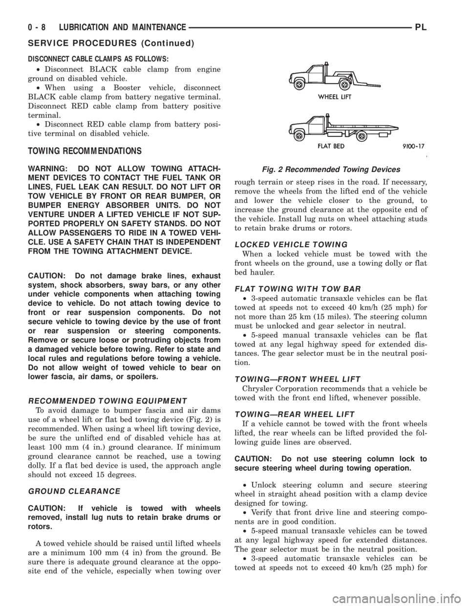
use of a wheel lift or flat bed towing device (Fig. 2) is
recommended. When using a wheel lift towing device,
be sure the unlifted end of disabled vehicle has at
least 100 mm (4 in.) ground clearance. If minimum
ground clearance cannot be reached, use a towing
dolly. If a flat bed device is used, the approach angle
should not exceed 15 degrees.
GROUND CLEARANCE
CAUTION: If vehicle is towed with wheels
removed, install lug nuts to retain brake drums or
rotors.
A towed vehicle should be raised until lifted wheels
are a minimum 100 mm (4 in) from the ground. Be
sure there is adequate ground clearance at the oppo-
site end of the vehicle, especially when towing overrough terrain or steep rises in the road. If necessary,
remove the wheels from the lifted end of the vehicle
and lower the vehicle closer to the ground, to
increase the ground clearance at the opposite end of
the vehicle. Install lug nuts on wheel attaching studs
to retain brake drums or rotors.
LOCKED VEHICLE TOWING
When a locked vehicle must be towed with the
front wheels on the ground, use a towing dolly or flat
bed hauler.
FLAT TOWING WITH TOW BAR
²3-speed automatic transaxle vehicles can be flat
towed at speeds not to exceed 40 km/h (25 mph) for
not more than 25 km (15 miles). The steering column
must be unlocked and gear selector in neutral.
²5-speed manual transaxle vehicles can be flat
towed at any legal highway speed for extended dis-
tances. The gear selector must be in the neutral posi-
tion.
TOWINGÐFRONT WHEEL LIFT
Chrysler Corporation recommends that a vehicle be
towed with the front end lifted, whenever possible.
TOWINGÐREAR WHEEL LIFT
If a vehicle cannot be towed with the front wheels
lifted, the rear wheels can be lifted provided the fol-
lowing guide lines are observed.
CAUTION: Do not use steering column lock to
secure steering wheel during towing operation.
²Unlock steering column and secure steering
wheel in straight ahead position with a clamp device
designed for towing.
²Verify that front drive line and steering compo-
nents are in good condition.
²5-speed manual transaxle vehicles can be towed
at any legal highway speed for extended distances.
The gear selector must be in the neutral position.
²3-speed automatic transaxle vehicles can be
towed at speeds not to exceed 40 km/h (25 mph) for
Fig. 2 Recommended Towing Devices
0 - 8 LUBRICATION AND MAINTENANCEPL
SERVICE PROCEDURES (Continued)
Page 83 of 1200
BASE BRAKE SYSTEM
INDEX
page page
DESCRIPTION AND OPERATION
CHASSIS TUBES AND HOSES.............. 6
FRONT DISC BRAKES..................... 2
MASTER CYLINDER...................... 6
PARKING BRAKES........................ 4
PROPORTIONING VALVES................. 5
REAR DISC BRAKES...................... 4
REAR DRUM BRAKES..................... 4
REAR WHEEL HUB/BEARING............... 8
RED BRAKE WARNING LAMP............... 7
STOP LAMP SWITCH...................... 8
VACUUM BOOSTER...................... 6
DIAGNOSIS AND TESTING
BRAKE FLUID CONTAMINATION............ 19
BRAKE SYSTEM BASIC DIAGNOSIS GUIDE.... 9
BRAKE SYSTEM DIAGNOSIS CHARTS....... 10
DRUM BRAKE AUTOMATIC ADJUSTER....... 14
PROPORTIONING VALVES................ 16
RED BRAKE WARNING LAMP TEST......... 19
ROTOR THICKNESS AND RUNOUT.......... 14
STOP LAMP SWITCH TEST PROCEDURE..... 19
SERVICE PROCEDURES
BRAKE BLEEDING....................... 20
BRAKE DRUM MACHINING................ 23
BRAKE FLUID LEVEL CHECK.............. 19
BRAKE ROTOR MACHINING............... 22
BRAKE TUBE REPAIR.................... 25
MASTER CYLINDER BLEEDING............ 21
PARK BRAKE LEVER AUTO ADJUSTER
MECHANISM.......................... 23
REMOVAL AND INSTALLATION
CHASSIS TUBES AND HOSES.............. 47
FRONT DISC BRAKE CALIPER............. 26
FRONT DISC BRAKE SHOES.............. 28
MASTER CYLINDER..................... 41
PARK BRAKE CABLES.................... 50
PARK BRAKE LEVER ASSEMBLY........... 48PARK BRAKE LEVER OUTPUT CABLE....... 49
PARK BRAKE SHOES WITH REAR DISC
BRAKES............................. 55
PROPORTIONING VALVE (BASE BRAKES).... 47
REAR BRAKE DRUM..................... 34
REAR BRAKE SHOE SUPPORT PLATE....... 37
REAR BRAKE SHOES.................... 35
REAR BRAKE WHEEL CYLINDER........... 38
REAR DISC BRAKE CALIPER.............. 30
REAR DISC BRAKE SHOES................ 32
REAR HUB/BEARING..................... 39
STOP LAMP SWITCH..................... 57
VACUUM BOOSTER..................... 44
WHEEL AND TIRE ASSEMBLY.............. 26
DISASSEMBLY AND ASSEMBLY
BRAKE FLUID LEVEL SWITCH............. 58
BRAKE FLUID RESERVOIR................ 57
FRONT AND REAR DISC BRAKE CALIPER.... 58
WHEEL CYLINDER (REAR DRUM BRAKE).... 63
CLEANING AND INSPECTION
CHASSIS TUBES AND HOSES.............. 65
FRONT DISC BRAKES.................... 63
REAR DISC BRAKES..................... 64
REAR DRUM BRAKE WHEEL CYLINDER...... 65
REAR DRUM BRAKES.................... 64
REAR WHEEL HUB AND BEARING ASSEMBLY . 65
ADJUSTMENTS
PARK BRAKE ADJUSTMENT............... 66
REAR DRUM BRAKE SHOE ADJUSTMENT.... 65
STOP LAMP SWITCH..................... 65
SPECIFICATIONS
BRAKE ACTUATION SYSTEM.............. 67
BRAKE FASTENER TORQUE SPECIFICATIONS . 67
BRAKE FLUID.......................... 67
SPECIAL TOOLS
BASE BRAKE SYSTEM................... 68
DESCRIPTION AND OPERATION
FRONT DISC BRAKES
The front disc brakes (Fig. 1) and (Fig. 2) consists
of the following components:
²The driving hub
²Braking disc (rotor)
²Caliper assembly - single piston, floating type
²Brake shoes and linings
The double pin calipers are mounted directly to the
steering knuckles and use no adapter. The caliper ismounted to the steering knuckle using bushings,
sleeves and 2 guide pin bolts which thread directly
into bosses on the steering knuckle (Fig. 2) and (Fig.
3).
Two machined abutments on the steering knuckle
position the caliper. The guide pin bolts, sleeves and
bushings control the side to side movement of the
caliper. The piston seal is designed to pull the piston
back into the bore of the caliper when the brake
pedal is released. This maintains the proper brake
shoe to rotor clearance (Fig. 4).
5 - 2 BRAKESPL
Page 85 of 1200
REAR DISC BRAKES
The rear disc brakes are similar to the front disc
brakes, however, there are several distinctive fea-
tures that require different service procedures. The
single piston, floating caliper rear disc brake assem-
bly includes a hub and bearing assembly, adapter,
brake rotor, caliper, brake pads/linings. The parking
brake system on all vehicles equipped with rear disc
brakes consists of a small duo-servo drum brake
mounted to the caliper adapter. The drum brake
shoes expand out against a braking surface (hat sec-
tion) on the inside area of the rotor.
Vehicles are equipped with a caliper assembly that
has a 34 mm (1.43 in.) piston and uses a solid non-
vented rotor.
The caliper assembly on all applications float on
rubber bushings using internal metal sleeves which
are attached to the adapter using threaded guide pin
bolts.
The adapter and rotor shield are mounted to the
rear suspension knuckles of vehicle. The adapter is
used to mount the brake shoes and actuating cables
for the parking brake system. The adapter also
mounts the rear caliper assembly to the vehicle. The
adapter has two machined abutments which are used
to position and align the caliper and brake pads for
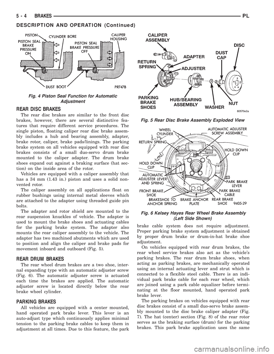
movement inboard and outboard (Fig. 5).
REAR DRUM BRAKES
The rear wheel drum brakes are a two shoe, inter-
nal expanding type with an automatic adjuster screw
(Fig. 6). The automatic adjuster screw is actuated
each time the brakes are applied. The automatic
adjuster screw is located directly below the rear
brake wheel cylinder.
PARKING BRAKES
All vehicles are equipped with a center mounted,
hand operated park brake lever. This lever is an
auto-adjust type which continuously applies minimal
tension to the parking brake cables to keep them in
adjustment at all times. Due to this feature, the parkbrake cable system does not require adjustment.
Proper parking brake system adjustment is obtained
by proper drum brake or drum-in-hat brake shoe
adjustment.
On vehicles equipped with rear drum brakes, the
rear wheel service brakes also act as the vehicle's
parking brakes. The rear drum brake shoes, when
acting as parking brakes, are mechanically operated
using an internal actuating lever and strut which is
connected to a flexible steel cable. There is an indi-
vidual park brake cable for each rear wheel, which
are joined using a park cable equalizer before termi-
nating at the floor mounted, hand operated park
brake lever.
The parking brakes on vehicles equipped with rear
disc brakes consist of a small duo-servo brake assem-
bly mounted to the disc brake caliper adapter (Fig.
7). The hat (center) section (Fig. 8) of the rear rotor
serves as the braking surface (drum) for the parking
brakes. This park brake application uses the same
Fig. 4 Piston Seal Function for Automatic
Adjustment
Fig. 5 Rear Disc Brake Assembly Exploded View
Fig. 6 Kelsey Hayes Rear Wheel Brake Assembly
(Left Side Shown)
5 - 4 BRAKESPL
DESCRIPTION AND OPERATION (Continued)
Page 87 of 1200
portioning valve has a different part number. During
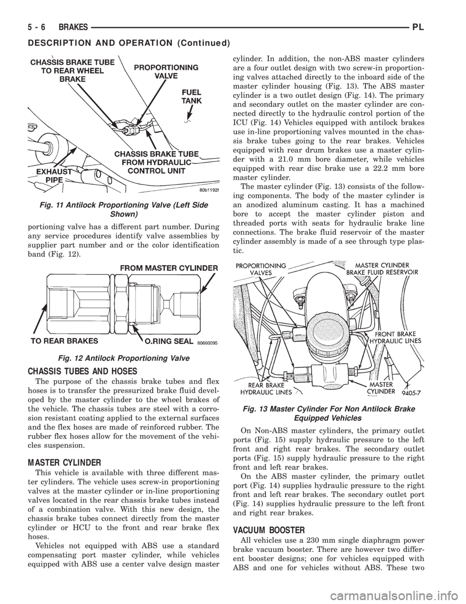
any service procedures identify valve assemblies by
supplier part number and or the color identification
band (Fig. 12).
CHASSIS TUBES AND HOSES
The purpose of the chassis brake tubes and flex
hoses is to transfer the pressurized brake fluid devel-
oped by the master cylinder to the wheel brakes of
the vehicle. The chassis tubes are steel with a corro-
sion resistant coating applied to the external surfaces
and the flex hoses are made of reinforced rubber. The
rubber flex hoses allow for the movement of the vehi-
cles suspension.
MASTER CYLINDER
This vehicle is available with three different mas-
ter cylinders. The vehicle uses screw-in proportioning
valves at the master cylinder or in-line proportioning
valves located in the rear chassis brake tubes instead
of a combination valve. With this new design, the
chassis brake tubes connect directly from the master
cylinder or HCU to the front and rear brake flex
hoses.
Vehicles not equipped with ABS use a standard
compensating port master cylinder, while vehicles
equipped with ABS use a center valve design mastercylinder. In addition, the non-ABS master cylinders
are a four outlet design with two screw-in proportion-
ing valves attached directly to the inboard side of the
master cylinder housing (Fig. 13). The ABS master
cylinder is a two outlet design (Fig. 14). The primary
and secondary outlet on the master cylinder are con-
nected directly to the hydraulic control portion of the
ICU (Fig. 14) Vehicles equipped with antilock brakes
use in-line proportioning valves mounted in the chas-
sis brake tubes going to the rear brakes. Vehicles
equipped with rear drum brakes use a master cylin-
der with a 21.0 mm bore diameter, while vehicles
equipped with rear disc brake use a 22.2 mm bore
master cylinder.
The master cylinder (Fig. 13) consists of the follow-
ing components. The body of the master cylinder is
an anodized aluminum casting. It has a machined
bore to accept the master cylinder piston and
threaded ports with seats for hydraulic brake line
connections. The brake fluid reservoir of the master
cylinder assembly is made of a see through type plas-
tic.
On Non-ABS master cylinders, the primary outlet
ports (Fig. 15) supply hydraulic pressure to the left
front and right rear brakes. The secondary outlet
ports (Fig. 15) supply hydraulic pressure to the right
front and left rear brakes.
On the ABS master cylinder, the primary outlet
port (Fig. 14) supplies hydraulic pressure to the right
front and left rear brakes. The secondary outlet port
(Fig. 14) supplies hydraulic pressure to the left front
and right rear brakes.
VACUUM BOOSTER
All vehicles use a 230 mm single diaphragm power
brake vacuum booster. There are however two differ-
ent booster designs; one for vehicles equipped with
ABS and one for vehicles without ABS. These two
Fig. 11 Antilock Proportioning Valve (Left Side
Shown)
Fig. 12 Antilock Proportioning Valve
Fig. 13 Master Cylinder For Non Antilock Brake
Equipped Vehicles
5 - 6 BRAKESPL
DESCRIPTION AND OPERATION (Continued)
Page 89 of 1200

either through the park brake switch, the fluid level
sensor in the master cylinder reservoir, or the igni-
tion switch in the crank position.
The Brake Fluid Level sensor is located in the
brake fluid reservoir of the master cylinder assembly
(Fig. 18). The purpose of the sensor is to provide the
driver with an early warning that the brake fluid
level in the master cylinder reservoir has dropped to
below normal. This may indicate an abnormal loss of
brake fluid in the master cylinder fluid reservoir
resulting from a leak in the hydraulic system.
As the fluid drops below the minimum level, the
fluid level sensor closes the brake warning light cir-
cuit. This will turn on the red brake warning light.
At this time, master cylinder fluid reservoir shouldbe checked and filled to the full mark with DOT 3
brake fluid.If brake fluid level has dropped in
master cylinder fluid reservoir, the entire
brake hydraulic system should be checked for
evidence of a leak.
STOP LAMP SWITCH
The stop lamp switch controls operation of the
vehicles stop lamps. Also, if the vehicle is equipped
with speed control, the stop lamp switch will deacti-
vate speed control when the brake pedal is
depressed.
The stop lamp switch controls operation of the
right and left tail, stop and turn signal lamp and
CHMSL lamp, by supplying battery current to these
lamps.
The stop lamp switch controls the lamp operation
by opening and closing the electrical circuit to the
stop lamps.
REAR WHEEL HUB/BEARING
CAUTION: If a vehicle is equipped with antilock
brakes the tone wheels for the rear wheel speed
sensors are pressed onto the hub. The tone wheels
used on this vehicle equipped with the Teves Mark
20 Antilock Brake System are different then those
used on past models of this vehicle equipped with
antilock brakes. Reduced braking performance will
result if this part is used on earlier model vehicles
and an accident could result. Do not use on
pre-1998 model year vehicles.
All vehicles are equipped with permanently lubri-
cated and sealed for life rear wheel bearings. There
is no periodic lubrication or maintenance recom-
mended for these units. However, if servicing of a
rear wheel bearing is required, refer to procedures in
the diagnosis and testing section and the removal
and installation section in this group of the service
manual for the inspection and replacement of the
rear wheel bearing.Fig. 17 Power Brake Booster Assembly
Fig. 18 Master Cylinder Fluid Level Sensor
5 - 8 BRAKESPL
DESCRIPTION AND OPERATION (Continued)
Page 91 of 1200
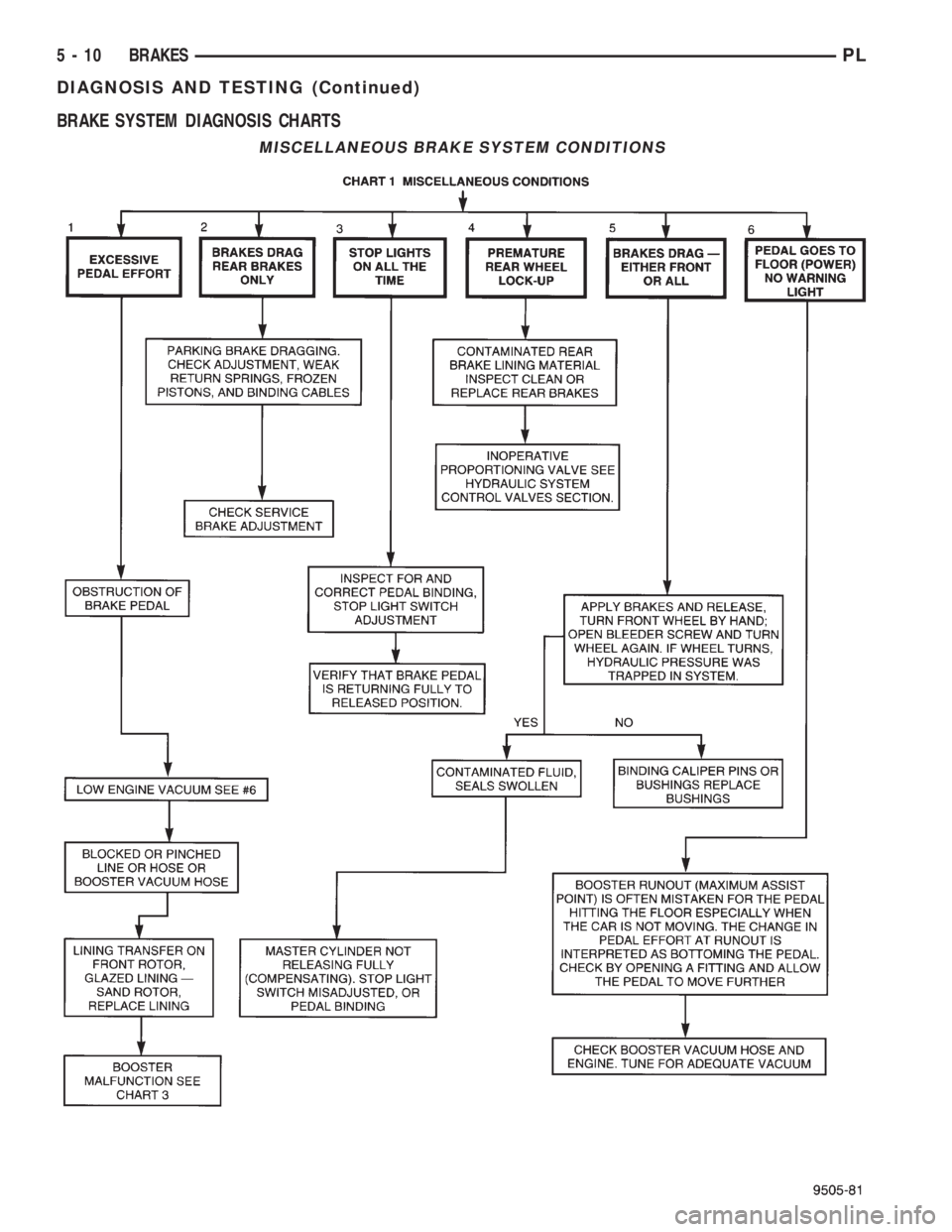
BRAKE SYSTEM DIAGNOSIS CHARTS
MISCELLANEOUS BRAKE SYSTEM CONDITIONS
5 - 10 BRAKESPL
DIAGNOSIS AND TESTING (Continued)
Page 93 of 1200
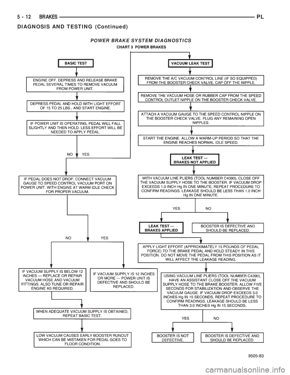
POWER BRAKE SYSTEM DIAGNOSTICS
5 - 12 BRAKESPL
DIAGNOSIS AND TESTING (Continued)
Page 95 of 1200
DRUM BRAKE AUTOMATIC ADJUSTER
Place the vehicle on a hoist with a helper in the
driver's seat to apply the brakes. Remove the access
plug from the rear adjustment slot in each brake
support plate to provide access to the adjuster star
wheel. Then, to eliminate the possibility of maximum
adjustment, back the star wheel off approximately 10
notches. It will be necessary to hold the adjuster
lever away from the star wheel to permit this adjust-
ment.
Apply the brake pedal. This application of force
will cause the brake shoes to leave the anchor. Upon
application of the brake pedal, the lever should move
downward, turning the star wheel. Thus, a definite
rotation of the adjuster star wheel can be observed if
the automatic adjuster is working properly. If one or
more adjusters do not function properly, the respec-
tive drum must be removed for adjuster servicing.
ROTOR THICKNESS AND RUNOUT
Any servicing of the rotor requires extreme care to
maintain the rotor within service tolerances to
ensure proper brake action.
Before refinishing or refacing a rotor, the disc
should be checked and inspected for the following
conditions:
Braking surface scoring, rust, impregnation of lin-
ing material and worn ridges.
Excessive lateral runout or wobble.
Thickness variation (Parallelism).
Dishing or distortion (Flatness).
If a vehicle has not been driven for a period of
time, the rotor surface will rust in the area not cov-
ered by the brake lining and cause noise and chatter
when the brakes are applied.
Excessive wear and scoring of the rotor can cause
temporary improper lining contact if ridges are not
removed before installation of new brake pad assem-
blies.
Some discoloration or wear of the rotor surface is
normal and does not require resurfacing when lin-
ings are replaced.
Excessive runout or wobble in a rotor can increase
pedal travel due to piston knock back. This will
increase guide pin sleeve wear due to tendency of cal-
iper to follow rotor wobble.
Thickness variation in a rotor can also result in
pedal pulsation, chatter and surge due to variation in
brake output. This can also be caused by excessive
runout in rotor or hub.
Dishing or distortion can be caused by extreme
heat and abuse of the brakes.
ROTOR RUNOUT AND THICKNESS VARIATION
On vehicle rotor runout is the combination of the
individual runout of the hub face and the runout ofthe rotor. (The hub and rotor runouts are separable).
To measure runout on the vehicle, remove the wheel
and reinstall the lug nuts tightening the rotor to the
hub. Mount Dial Indicator, Special Tool C-3339 with
Mounting Adaptor, Special Tool SP- 1910 on steering
arm. Dial indicator plunger should contact braking
surface of rotor approximately one inch from edge of
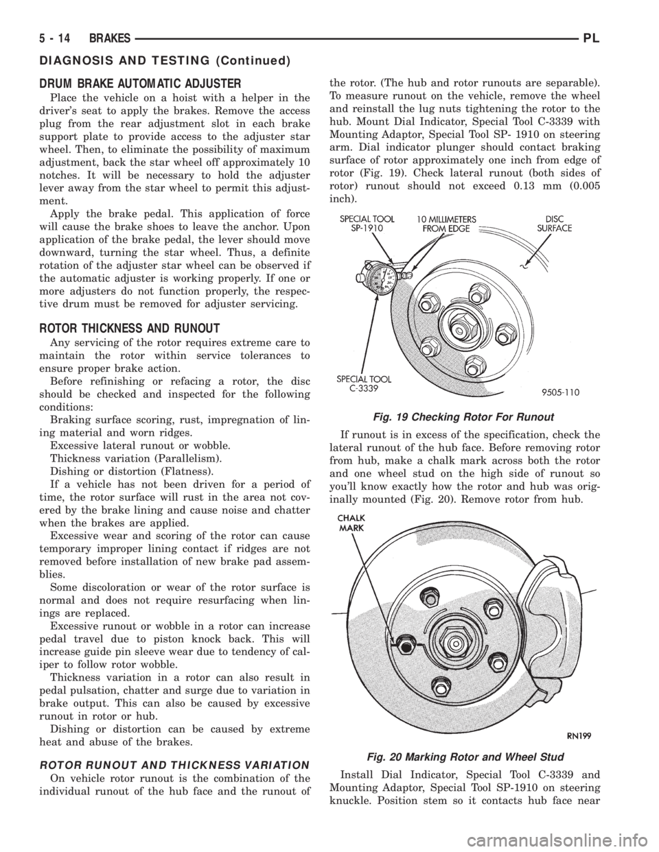
rotor (Fig. 19). Check lateral runout (both sides of
rotor) runout should not exceed 0.13 mm (0.005
inch).
If runout is in excess of the specification, check the
lateral runout of the hub face. Before removing rotor
from hub, make a chalk mark across both the rotor
and one wheel stud on the high side of runout so
you'll know exactly how the rotor and hub was orig-
inally mounted (Fig. 20). Remove rotor from hub.
Install Dial Indicator, Special Tool C-3339 and
Mounting Adaptor, Special Tool SP-1910 on steering
knuckle. Position stem so it contacts hub face near
Fig. 19 Checking Rotor For Runout
Fig. 20 Marking Rotor and Wheel Stud
5 - 14 BRAKESPL
DIAGNOSIS AND TESTING (Continued)