1999 DODGE NEON ESP
[x] Cancel search: ESPPage 143 of 1200
(12) Inspect caliper piston for pitting, scratches, or
any physical damage. Replace piston if there is evi-
dence of scratches, pitting or physical damage.
CALIPER ASSEMBLY
CAUTION: Excessive vise pressure will cause bore
distortion and binding of piston.
(1) Clamp caliper in a vise (with protective caps
installed on jaws of vise).
(2) Dip new piston seal in clean brake fluid and
install in the groove of the caliper bore. Seal should
be positioned at one area in groove and gently
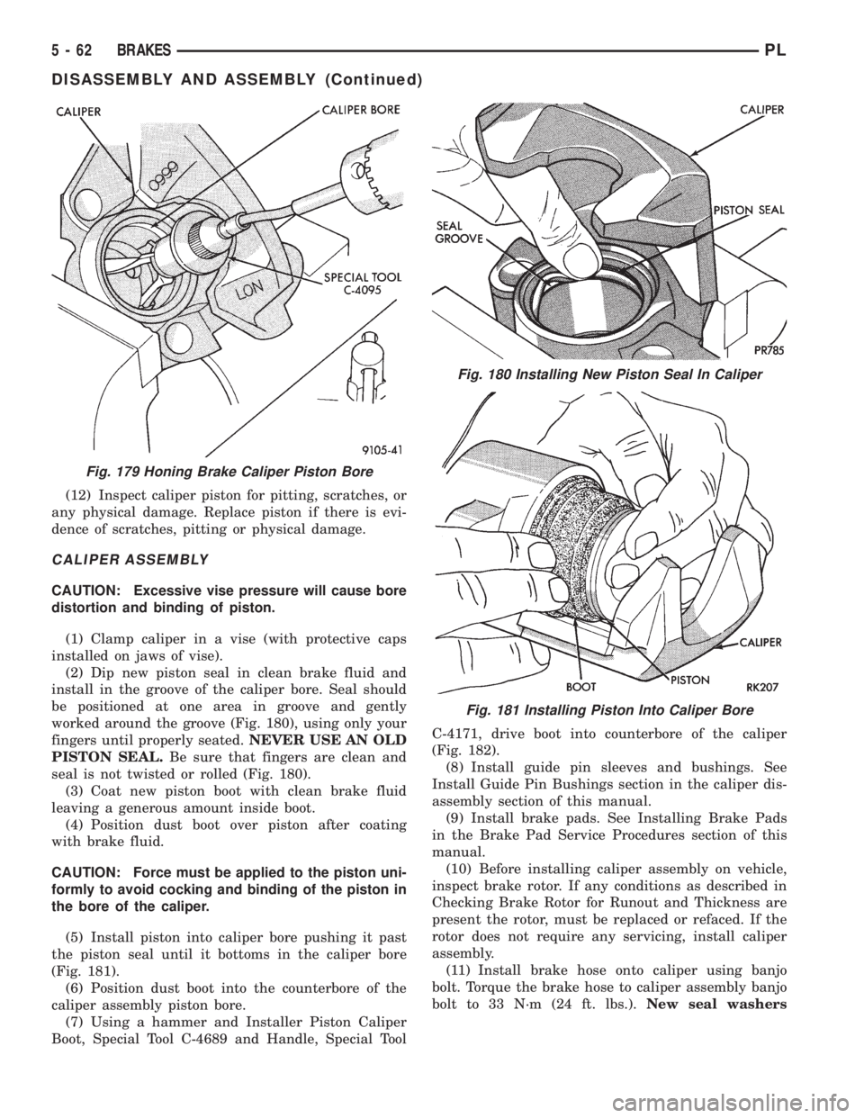
worked around the groove (Fig. 180), using only your
fingers until properly seated.NEVER USE AN OLD
PISTON SEAL.Be sure that fingers are clean and
seal is not twisted or rolled (Fig. 180).
(3) Coat new piston boot with clean brake fluid
leaving a generous amount inside boot.
(4) Position dust boot over piston after coating
with brake fluid.
CAUTION: Force must be applied to the piston uni-
formly to avoid cocking and binding of the piston in
the bore of the caliper.
(5) Install piston into caliper bore pushing it past
the piston seal until it bottoms in the caliper bore
(Fig. 181).
(6) Position dust boot into the counterbore of the
caliper assembly piston bore.
(7) Using a hammer and Installer Piston Caliper
Boot, Special Tool C-4689 and Handle, Special ToolC-4171, drive boot into counterbore of the caliper
(Fig. 182).
(8) Install guide pin sleeves and bushings. See
Install Guide Pin Bushings section in the caliper dis-
assembly section of this manual.
(9) Install brake pads. See Installing Brake Pads
in the Brake Pad Service Procedures section of this
manual.
(10) Before installing caliper assembly on vehicle,
inspect brake rotor. If any conditions as described in
Checking Brake Rotor for Runout and Thickness are
present the rotor, must be replaced or refaced. If the
rotor does not require any servicing, install caliper
assembly.
(11) Install brake hose onto caliper using banjo
bolt. Torque the brake hose to caliper assembly banjo
bolt to 33 N´m (24 ft. lbs.).New seal washers
Fig. 179 Honing Brake Caliper Piston Bore
Fig. 180 Installing New Piston Seal In Caliper
Fig. 181 Installing Piston Into Caliper Bore
5 - 62 BRAKESPL
DISASSEMBLY AND ASSEMBLY (Continued)
Page 145 of 1200
is damaged, or a fluid leak is visible, disassemble cal-
iper assembly and install a new seal and boot, and
piston if scored. Refer to Front Disc Brake Caliper in
the Disassembly And Assembly Section in this group
of the service manual.
Check the guide pin dust boots to determine if they
are in good condition. Replace if they are damaged,
dry, or found to be brittle. Refer to Front Disc Brake
Caliper in the Disassembly And Assembly Section in
this group of the service manual.
REAR DISC BRAKES
BRAKE PAD LINING WEAR
If a visual inspection does not adequately deter-
mine the condition of the lining, a physical check will
be necessary. To check the amount of lining wear,
remove the wheel and tire assemblies, and the cali-
pers.
Remove the rear disc brake shoes. Refer to Rear
Disc Brake Shoe Removal in the Removal And Instal-
lation section in this group of the service manual for
the required procedure.
The combined brake shoe and lining material
thickness should be measured at the thinnest part of
the assembly.
When a set of brake shoes are worn to a total
thickness of approximately 7.0 mm (9/32 inch) they
should be replaced.
Replacebothbrake shoe assemblies (inboard and
outboard). It is necessary thatbothrear wheel sets
be replaced whenever brake shoe assemblies on
either side are replaced.
If the brake shoe assemblies do not require
replacement, reinstall, the assemblies making sureeach brake shoe is returned to the original position.
Refer to Rear Disc Brake Shoe Installation in the
Removal And Installation section in this group of the
service manual for the required procedure.
CALIPER INSPECTION
Check for brake fluid leaks in and around boot
area and inboard lining, and for any ruptures, brit-
tleness or damage to the piston dust boot. If the boot
is damaged, or a fluid leak is visible, disassemble cal-
iper assembly and install a new seal and boot, and
piston if scored. Refer to Rear Disc Brake Caliper in
the Disassembly And Assembly Section in this group
of the service manual.
Check the guide pin dust boots to determine if they
are in good condition. Replace if they are damaged,
dry, or found to be brittle. Refer to Rear Disc Brake
Caliper in the Disassembly And Assembly Section in
this group of the service manual.
REAR DRUM BRAKES
Rear brake shoe lining should show contact across
entire width of the lining and also from the heel to
the toe of the lining, otherwise replace.
Brake shoes with lack of contact at the toe or heel
of the brake shoe linng may be improperly ground.
Clean and inspect the brake support plate and
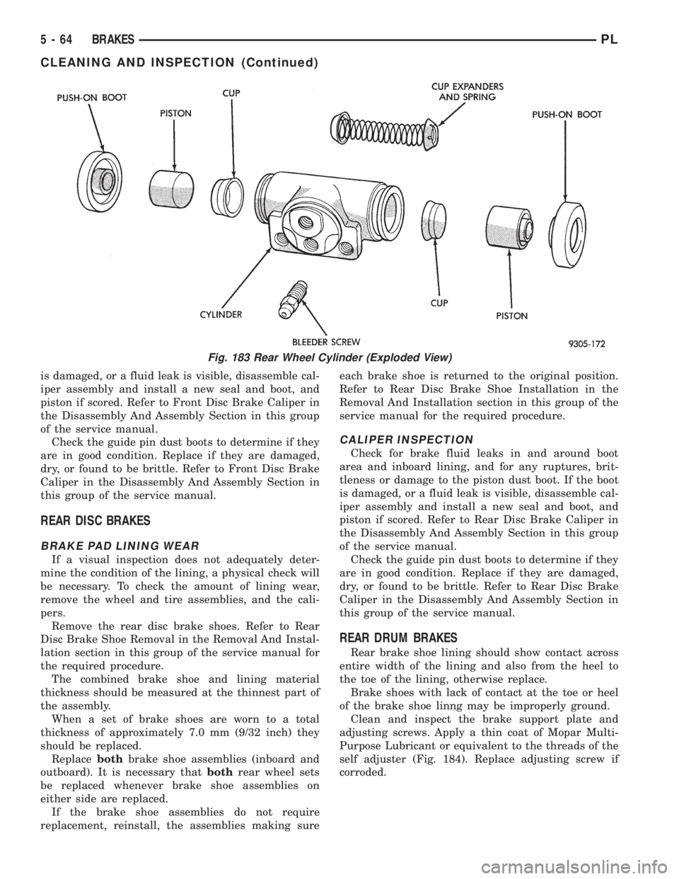
adjusting screws. Apply a thin coat of Mopar Multi-
Purpose Lubricant or equivalent to the threads of the
self adjuster (Fig. 184). Replace adjusting screw if
corroded.
Fig. 183 Rear Wheel Cylinder (Exploded View)
5 - 64 BRAKESPL
CLEANING AND INSPECTION (Continued)
Page 147 of 1200
(3)Be sure parking brake lever is fully
released.
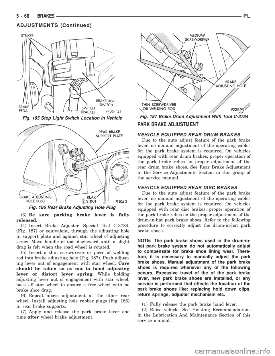
(4) Insert Brake Adjuster, Special Tool C-3784,
(Fig. 187) or equivalent, through the adjusting hole
in support plate and against star wheel of adjusting
screw. Move handle of tool downward until a slight
drag is felt when the road wheel is rotated.
(5) Insert a thin screwdriver or piece of welding
rod into brake adjusting hole (Fig. 187). Push adjust-
ing lever out of engagement with star wheel.Care
should be taken so as not to bend adjusting
lever or distort lever spring.While holding
adjusting lever out of engagement with star wheel,
back off star wheel to ensure a free wheel with no
brake shoe drag.
(6) Repeat above adjustment at the other rear
wheel. Install adjusting hole rubber plugs (Fig. 186)
in rear brake supports.
(7) Apply and release the park brake lever one
timeafterwheel brake adjustment.
PARK BRAKE ADJUSTMENT
VEHICLE EQUIPPED REAR DRUM BRAKES
Due to the auto adjust feature of the park brake
lever, no manual adjustment of the operating cables
for the park brake system is required. On vehicles
equipped with rear drum brakes, proper operation of
the park brake relies on proper adjustment of the
rear drum brake shoes. See Rear Brake Adjustment
in the Service Adjustments Section in this group of
the service manual.
VEHICLE EQUIPPED REAR DISC BRAKES
Due to the auto adjust feature of the park brake
lever, no manual adjustment of the operating cables
for the park brake system is required. On vehicles
equipped with rear disc brakes, proper operation of
the park brake relies on the proper adjustment of the
drum-in-hat park brake shoes. Refer to the following
procedure to correctly adjust the drum-in-hat park
brake shoes.
NOTE: The park brake shoes used in the drum-in-
hat park brake system do not automatically adjust
to compensate for brake shoe lining wear. There-
fore, it is necessary to manually adjust the park
brake shoes. Manual adjustment of the park brake
shoes is required whenever any of the following
occurs. Excessive travel of the of the park brake
lever, new park brake shoes are installed, or any
service is performed that effects the location of the
park brake shoes like: replacing hold down clips,
return springs, adjuster mechanism etc.
(1) Fully release the park brake hand lever.
(2) Raise vehicle. See Hoisting Recommendations
in the Lubrication And Maintenance Section of this
service manual.
Fig. 185 Stop Light Switch Location In Vehicle
Fig. 186 Rear Brake Adjusting Hole Plug
Fig. 187 Brake Drum Adjustment With Tool C-3784
5 - 66 BRAKESPL
ADJUSTMENTS (Continued)
Page 149 of 1200
DESCRIPTION TORQUE
MASTER CYLINDER:
To Vacuum Booster Mounting Nut.28 N´m (250 in. lbs.)
BRAKE BOOSTER:
To Dash Panel Mounting Nuts . .28 N´m (250 in. lbs.)
REAR WHEEL CYLINDER:
To Support Plate Mounting Bolts.13 N´m (115 in. lbs.)
Bleeder Screw...............10N´m(80in.lbs.)
BRAKE SUPPORT PLATE:
To Axle Mounting Bolts.........75N´m(55ft.lbs.)
REAR DISC BRAKE ADAPTER:
To Axle Mounting Bolts.........75N´m(55ft.lbs.)
DISC BRAKE CALIPER:
Guide Pin Bolts.............22N´m(192 in. lbs.)
Bleeder Screw..............15N´m(125 in. lbs.)
ABS HYDRAULIC CONTROL UNIT:
To Mounting Bracket Bolts.....28N´m(250 in. lbs.)
Bracket To Frame Rail Mounting Bolt (Top) . .18 N´m
(160 in. lbs.)
Bracket To Frame Rail Mounting Bolts (Side).22 N´m
(200 in. lbs.)
PARKING BRAKE:
Lever Mounting Nuts.........28N´m(250 in. lbs.)
REAR HUB AND BEARING:
To Knuckle Retaining Nut.....217 N´m (160 ft. lbs.)
WHEEL:
Stud Lug Nut........109±150 N´m (80±110 ft. lbs.)
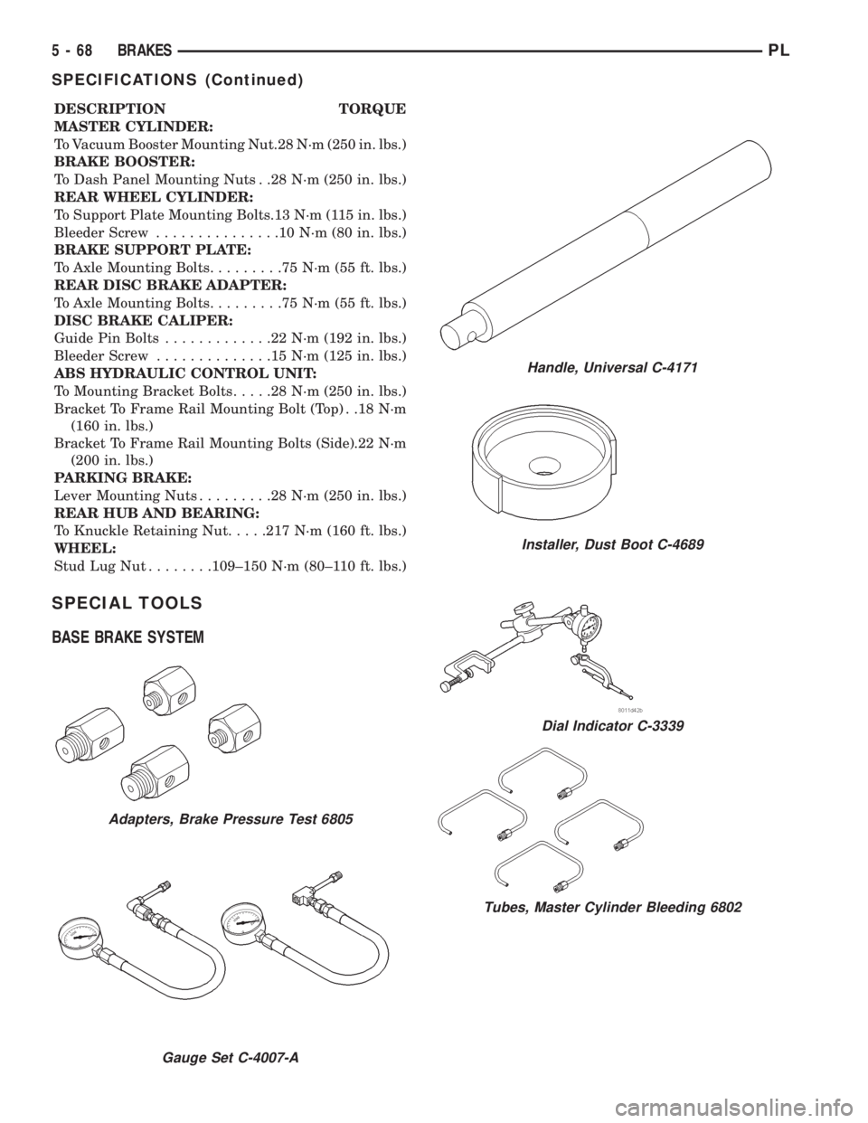
SPECIAL TOOLS
BASE BRAKE SYSTEM
Adapters, Brake Pressure Test 6805
Gauge Set C-4007-A
Handle, Universal C-4171
Installer, Dust Boot C-4689
Dial Indicator C-3339
Tubes, Master Cylinder Bleeding 6802
5 - 68 BRAKESPL
SPECIFICATIONS (Continued)
Page 151 of 1200
This is accomplished by a sophisticated system of
electrical and hydraulic components. As a result,
there are a few performance characteristics that may
at first seem different but should be considered nor-
mal. These characteristics are discussed below.
NORMAL BRAKING SYSTEM FUNCTION
Under normal braking conditions, the ABS System
functions the same as a standard brake system with
a diagonally split master cylinder and conventional
vacuum assist.
ABS SYSTEM OPERATION
If a wheel locking tendency is detected during a
brake application, the brake system will enter the
ABS mode. During ABS braking, hydraulic pressure
in the four wheel circuits is modulated to prevent
any wheel from locking. Each wheel circuit is
designed with a set of electric solenoids to allow mod-
ulation, although for vehicle stability, both rear
wheel solenoids receive the same electrical signal.
During an ABS stop, the brakes hydraulic system
is still diagonally split. However, the brake system
pressure is further split into four control channels.
During antilock operation of the vehicle's brake sys-
tem the front wheels are controlled independently
and are on two separate control channels and the
rear wheels of the vehicle are controlled together.
The system can build and release pressure at each
wheel, depending on signals generated by the wheel
speed sensors (WSS) at each wheel and received at
the Controller Antilock Brake (CAB).
ABS operation is available at all vehicle speeds
above 3 to 5 mph. Wheel lockup may be perceived at
the very end of an ABS stop and is considered nor-
mal.
VEHICLE HANDLING PERFORMANCE DURING
ABS BRAKING
It is important to remember that an antilock brake
system does not shorten a vehicle's stopping distance
under all driving conditions, but does provide
improved control of the vehicle while stopping. Vehi-
cle stopping distance is still dependent on vehicle
speed, weight, tires, road surfaces and other factors.
Though ABS provides the driver with some steer-
ing control during hard braking, there are conditions
however, where the system does not provide any ben-
efit. In particular, hydroplaning is still possible when
the tires ride on a film of water. This results in the
vehicles tires leaving the road surface rendering the
vehicle virtually uncontrollable. In addition, extreme
steering maneuvers at high speed or high speed cor-
nering beyond the limits of tire adhesion to the road
surface may cause vehicle skidding, independent of
vehicle braking. For this reason, the ABS system is
termed Antilock instead of Anti-Skid.
NOISE AND BRAKE PEDAL FEEL
During ABS braking, some brake pedal movement
may be felt. In addition, ABS braking will create
ticking, popping and/or groaning noises heard by the
driver. This is normal due to pressurized fluid being
transferred between the master cylinder and the
brakes. If ABS operation occurs during hard braking,
some pulsation may be felt in the vehicle body due to
fore and aft movement of the suspension as brake
pressures are modulated.
At the end of an ABS stop, ABS will be turned off
when the vehicle is slowed to a speed of 3±4 mph.
There may be a slight brake pedal drop anytime that
the ABS is deactivated, such as at the end of the stop
when the vehicle speed is less then 3 mph or during
an ABS stop where ABS is no longer required. These
conditions will exist when a vehicle is being stopped
on a road surface with patches of ice, loose gravel or
sand on it. Also stopping a vehicle on a bumpy road
surface will activate ABS because of the wheel hop
caused by the bumps.
TIRE NOISE AND MARKS
Although the ABS system prevents complete wheel
lock-up, some wheel slip is desired in order to
achieve optimum braking performance. Wheel slip is
defined as follows, 0 percent slip means the wheel is
rolling freely and 100 percent slip means the wheel is
fully locked. During brake pressure modulation,
wheel slip is allowed to reach up to 25 to30%. This
means that the wheel rolling velocity is 25 to 30%
less than that of a free rolling wheel at a given vehi-
cle speed. This slip may result in some tire chirping,
depending on the road surface. This sound should not
be interpreted as total wheel lock-up.
Complete wheel lock up normally leaves black tire
marks on dry pavement. The ABS System will not
leave dark black tire marks since the wheel never
reaches a fully locked condition. Tire marks may
however be noticeable as light patched marks.
START UP CYCLE
When the ignition is turned on, a popping sound
and a slight brake pedal movement may be noticed.
Additionally, when the vehicle is first driven off a
humming may be heard and/or felt by the driver at
approximately 20 to 40 kph (12 to 25 mph). The ABS
warning lamp will also be on for up to 5 seconds
after the ignition is turned on. All of these conditions
are a normal function of ABS as the system is per-
forming a diagnosis check.
5 - 70 BRAKESPL
DESCRIPTION AND OPERATION (Continued)
Page 153 of 1200
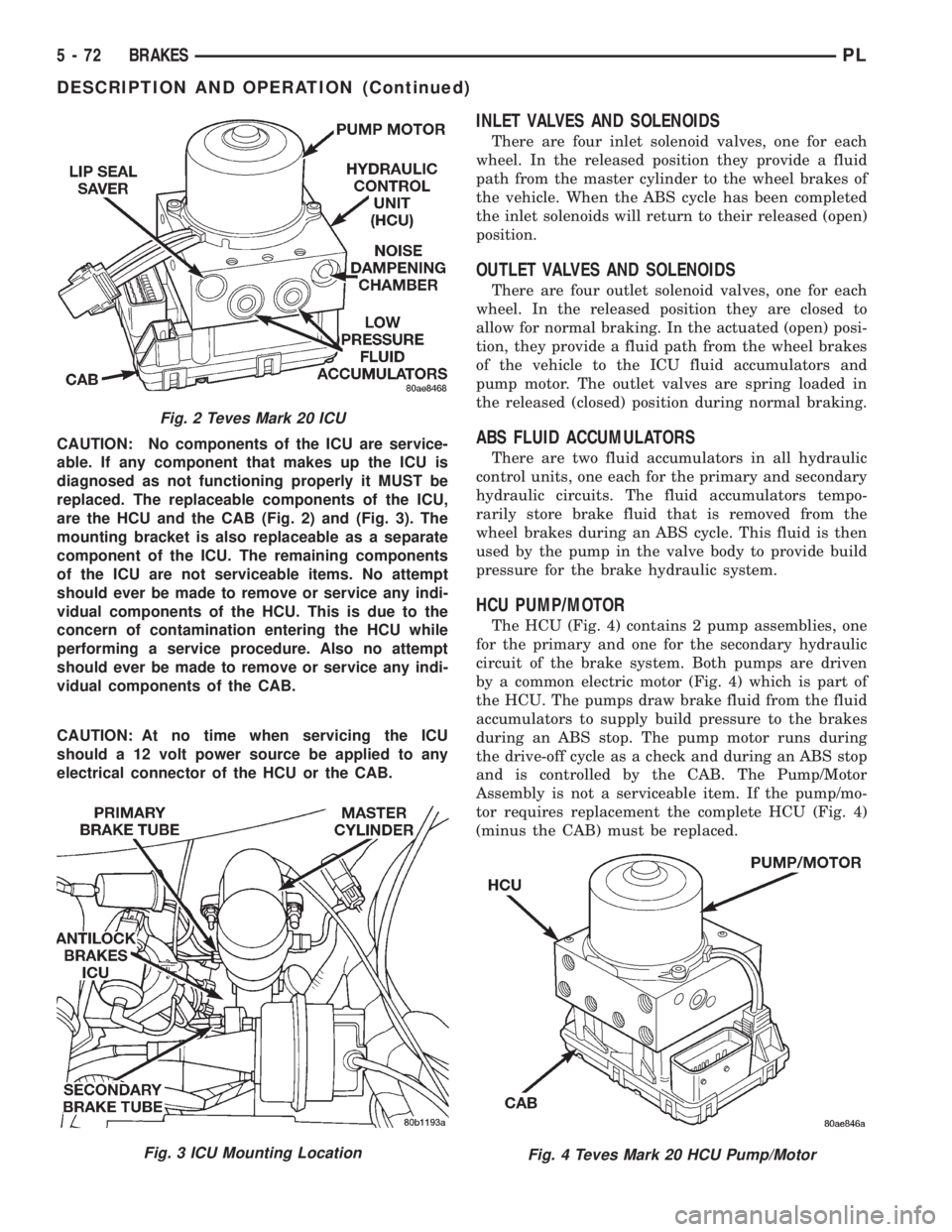
CAUTION: No components of the ICU are service-
able. If any component that makes up the ICU is
diagnosed as not functioning properly it MUST be
replaced. The replaceable components of the ICU,
are the HCU and the CAB (Fig. 2) and (Fig. 3). The
mounting bracket is also replaceable as a separate
component of the ICU. The remaining components
of the ICU are not serviceable items. No attempt
should ever be made to remove or service any indi-
vidual components of the HCU. This is due to the
concern of contamination entering the HCU while
performing a service procedure. Also no attempt
should ever be made to remove or service any indi-
vidual components of the CAB.
CAUTION: At no time when servicing the ICU
should a 12 volt power source be applied to any
electrical connector of the HCU or the CAB.
INLET VALVES AND SOLENOIDS
There are four inlet solenoid valves, one for each
wheel. In the released position they provide a fluid
path from the master cylinder to the wheel brakes of
the vehicle. When the ABS cycle has been completed
the inlet solenoids will return to their released (open)
position.
OUTLET VALVES AND SOLENOIDS
There are four outlet solenoid valves, one for each
wheel. In the released position they are closed to
allow for normal braking. In the actuated (open) posi-
tion, they provide a fluid path from the wheel brakes
of the vehicle to the ICU fluid accumulators and
pump motor. The outlet valves are spring loaded in
the released (closed) position during normal braking.
ABS FLUID ACCUMULATORS
There are two fluid accumulators in all hydraulic
control units, one each for the primary and secondary
hydraulic circuits. The fluid accumulators tempo-
rarily store brake fluid that is removed from the
wheel brakes during an ABS cycle. This fluid is then
used by the pump in the valve body to provide build
pressure for the brake hydraulic system.
HCU PUMP/MOTOR
The HCU (Fig. 4) contains 2 pump assemblies, one
for the primary and one for the secondary hydraulic
circuit of the brake system. Both pumps are driven
by a common electric motor (Fig. 4) which is part of
the HCU. The pumps draw brake fluid from the fluid
accumulators to supply build pressure to the brakes
during an ABS stop. The pump motor runs during
the drive-off cycle as a check and during an ABS stop
and is controlled by the CAB. The Pump/Motor
Assembly is not a serviceable item. If the pump/mo-
tor requires replacement the complete HCU (Fig. 4)
(minus the CAB) must be replaced.
Fig. 2 Teves Mark 20 ICU
Fig. 3 ICU Mounting LocationFig. 4 Teves Mark 20 HCU Pump/Motor
5 - 72 BRAKESPL
DESCRIPTION AND OPERATION (Continued)
Page 155 of 1200
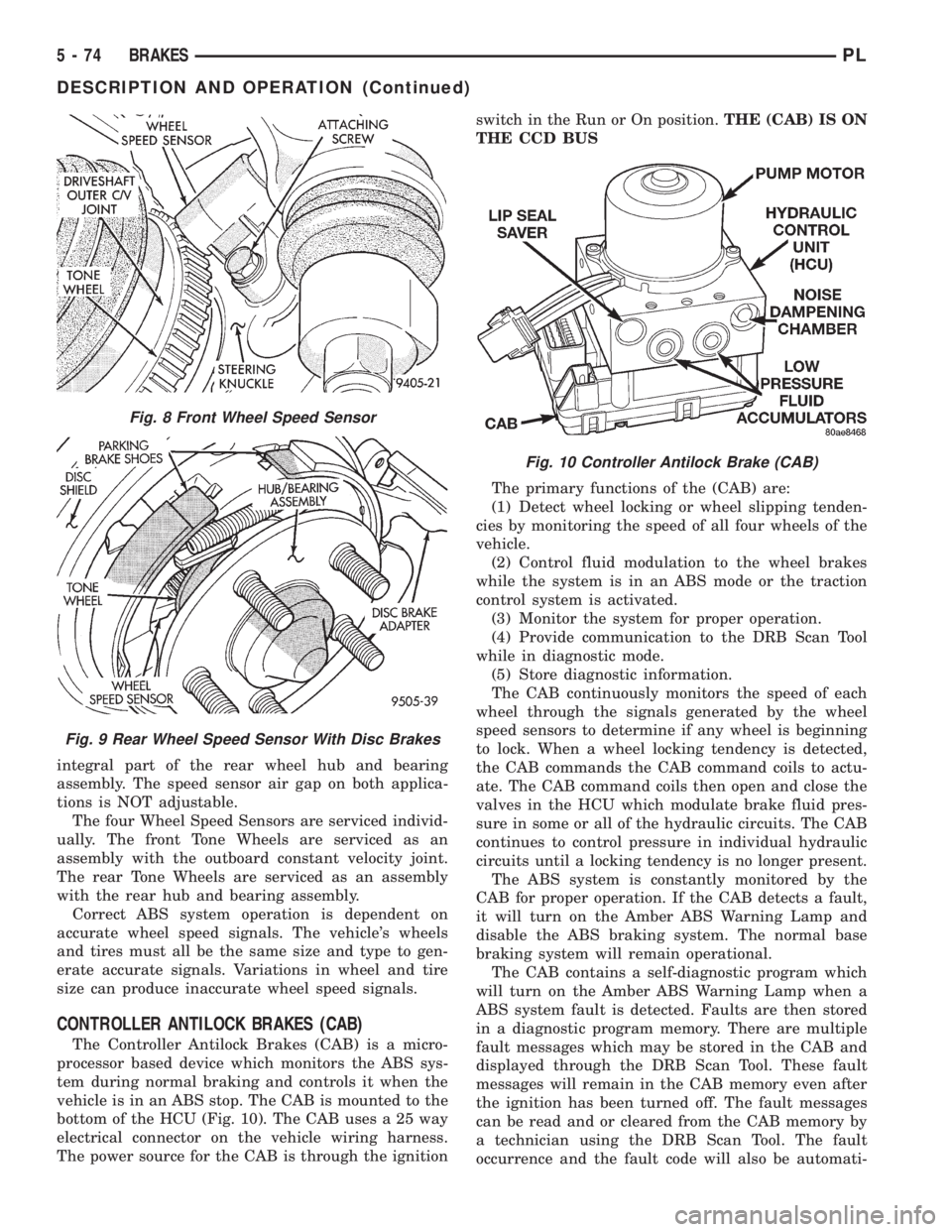
integral part of the rear wheel hub and bearing
assembly. The speed sensor air gap on both applica-
tions is NOT adjustable.
The four Wheel Speed Sensors are serviced individ-
ually. The front Tone Wheels are serviced as an
assembly with the outboard constant velocity joint.
The rear Tone Wheels are serviced as an assembly
with the rear hub and bearing assembly.
Correct ABS system operation is dependent on
accurate wheel speed signals. The vehicle's wheels
and tires must all be the same size and type to gen-
erate accurate signals. Variations in wheel and tire
size can produce inaccurate wheel speed signals.
CONTROLLER ANTILOCK BRAKES (CAB)
The Controller Antilock Brakes (CAB) is a micro-
processor based device which monitors the ABS sys-
tem during normal braking and controls it when the
vehicle is in an ABS stop. The CAB is mounted to the
bottom of the HCU (Fig. 10). The CAB uses a 25 way
electrical connector on the vehicle wiring harness.
The power source for the CAB is through the ignitionswitch in the Run or On position.THE (CAB) IS ON
THE CCD BUS
The primary functions of the (CAB) are:
(1) Detect wheel locking or wheel slipping tenden-
cies by monitoring the speed of all four wheels of the
vehicle.
(2) Control fluid modulation to the wheel brakes
while the system is in an ABS mode or the traction
control system is activated.
(3) Monitor the system for proper operation.
(4) Provide communication to the DRB Scan Tool
while in diagnostic mode.
(5) Store diagnostic information.
The CAB continuously monitors the speed of each
wheel through the signals generated by the wheel
speed sensors to determine if any wheel is beginning
to lock. When a wheel locking tendency is detected,
the CAB commands the CAB command coils to actu-
ate. The CAB command coils then open and close the
valves in the HCU which modulate brake fluid pres-
sure in some or all of the hydraulic circuits. The CAB
continues to control pressure in individual hydraulic
circuits until a locking tendency is no longer present.
The ABS system is constantly monitored by the
CAB for proper operation. If the CAB detects a fault,
it will turn on the Amber ABS Warning Lamp and
disable the ABS braking system. The normal base
braking system will remain operational.
The CAB contains a self-diagnostic program which
will turn on the Amber ABS Warning Lamp when a
ABS system fault is detected. Faults are then stored
in a diagnostic program memory. There are multiple
fault messages which may be stored in the CAB and
displayed through the DRB Scan Tool. These fault
messages will remain in the CAB memory even after
the ignition has been turned off. The fault messages
can be read and or cleared from the CAB memory by
a technician using the DRB Scan Tool. The fault
occurrence and the fault code will also be automati-
Fig. 8 Front Wheel Speed Sensor
Fig. 9 Rear Wheel Speed Sensor With Disc Brakes
Fig. 10 Controller Antilock Brake (CAB)
5 - 74 BRAKESPL
DESCRIPTION AND OPERATION (Continued)
Page 157 of 1200
and performance characteristics of the ABS. See the
ABS System Operation Section in this group of the
service manual to familiarize yourself with the oper-
ating principles of the ITT Teves Mark 20 ABS sys-
tem.
ABS SERVICE PRECAUTIONS
The ABS uses an electronic control module, the
CAB. This module is designed to withstand normal
current draws associated with vehicle operation.
Care must be taken to avoid overloading the CAB
circuits.In testing for open or short circuits, do
not ground or apply voltage to any of the cir-
cuits unless instructed to do so for a diagnostic
procedure.These circuits should only be tested
using a high impedance multi-meter or the DRB
tester as described in this section. Power should
never be removed or applied to any control module
with the ignition in the ON position. Before removing
or connecting battery cables, fuses, or connectors,
always turn the ignition to the OFF position.
CAUTION: Use only factory wiring harnesses. Do
not cut or splice wiring to the brake circuits. The
addition of after-market electrical equipment (car
phone, radar detector, citizen band radio, trailer
lighting, trailer brakes, ect.) on a vehicle equippedwith antilock brakes may affect the function of the
antilock brake system.
ABS WIRING DIAGRAM INFORMATION
During the diagnosis of the antilock brake system
it may become necessary to reference the wiring dia-
grams covering the antilock brake system and its
components. For wiring diagrams refer to Antilock
Brakes in Group 8W of this service manual. This
group will provide you with the wiring diagrams and
the circuit description and operation information cov-
ering the antilock brake system.
ABS DIAGNOSTICS MANUAL
Detailed procedures for diagnosing specific ABS
conditions are covered in the diagnostics manual cov-
ering the ITT Teves Mark 20 ABS system. The fol-
lowing information is presented to give the
technician a general background on the diagnostic
capabilities of the ITT Teves Mark 20 ABS system.
Please refer to the above mentioned manual for any
further electronic diagnostics and service procedures
that are required.
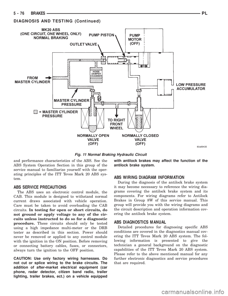
Fig. 11 Normal Braking Hydraulic Circuit
5 - 76 BRAKESPL
DIAGNOSIS AND TESTING (Continued)